1
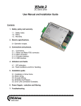
Whale3 servo drive user’s manual
1. Safety notices, policy and warranty.
1.1.Safety notes.
1.2.Policy.
1.3.Warranty.
2. Electric specifications and limitations.
2.1.Operation ranges.
3. Connections and pinouts.
3.1.Connectors.
3.1.1.Motor and Motor PSU connector.
3.1.2.Main connector.
3.1.3.Encoder interface.
3.1.4.USB interface.
3.1.5.In and outputs equivalent circuits.
4. Indicators and faults
4.1.LED indicators
4.2.Fault conditions
5. Installation guide.
5.1.Installation of drive frame.
4.2.Motor wiring.
4.3.Encoder wiring.
4.4.Shilding technics in general.
6. Power supply selection and filtering.
7. Troubleshooting.
1.1.Safety notes
Please read through this documentation before
operating the device.
The device can operate on low and medium DC bus
Voltages upto 80VDC. Above 50VDC, the drive’s metal
case must be connected to safety ground for safety
purpose.
Moving objects, like machine axis can be hazardous,
avoid touching and keep distance from mechanic moving
parts of the machine while the motor power supply is
on and connected to the drives.
The device should not be used where it can cause
personal injury, death or high financial loss.
Never open the drive’s chasis and never touch inner
circuity even if it’s unpowered.
Take care of power supply’s correct polarity
connection, wrong polarity connection of the Motor
Power supply will cause permament damage to the
device.
Never disconnect the motor from the drive when power
supply is connected to the drive and is under
Voltage.
Do not short the motor output terminals, it may cause
permament damage to the device.
The drives are in enclosure, but this metal case is
not meant to protect the drive from dust and falling
chips, liquid or other moisture material. Please take
care to protect the drives from taint damage.
1.2.Policy
CNCdrive cannot take responsibility for any personal
injury and/or financial loss caused by their drives’
failure or caused by following an error in this
documentation.
1.3.Warranty
We give 12 months of standard warranty period with
our Whale3 drives. Customers may send back the drives
within 15 days from purchase date if they are not
safisfied with the performace. Using the drives
outside of it’s specified electrical ranges may cause
permament damage to the device and void warranty.
Opening the drive’s metal frame and making any
modification in it voids warranty.
2. Electric specifications and limitations.
2.1. Operation ranges.
Property
Min
Typ
Max
Unit
Motor supply voltage
Motor current
12
0
-
80
20
VDC
A
Logic supply voltage
Logic supply current
Operating temperature
Opto-isolator
input Voltage
9
100
10
3
12
200
14
250
65
-
VDC
mA
°C
Opto-isolator current
Step input frequency
Direction signal stabile
state minimum allowed
valid time after step
signal active edge
Encoder maximum frequency
Switching frequency
Maximum continious motor
current
PID loop sampling time
Minimum allowed motor coil
resistance
3
0
1
5
1
10
400
1
mA
kHz
usec
1
20
20
1
20
20
1
20
20
MHz
kHz
Amper
1
1.5
1.5
65535
1.5
*60usec
Ohm
Minimum allowed motor
coil’s inductance
200
-
-
uH
-
Notes
Optimal U=rated+10..20%
Limited by drive at
treshold, max. at 20A
set
Automatic shutdown at 65°C
Use external series resistor
in case of input
Voltage>5VDC
Step signal active and
inactive edges can be
configured in software by
user.
With 4x coding
Current is limited at 20A
User setable in 60usec steps
If resistance is lower it
should be extended with
inductor or with
resistor/resistor wire.
If inductance of the motor
coil is lower, it shoud be
extended with series coil.
3.1.Connectors.
All connectors in the drive are fast „plug&play” like.
3.1.1.Motor and Motor Power supply connector.
This is a removable plug type 4 pin screw terminal for motor
connection (Arm1 and Arm2) and for high Voltage power bus Vdd+
and power GND.
3.1.2.Main connector.
The main connector have the input connections for digital
supply input, step and direction signal source connections and
restart , stop input connections and error in/output
(bidirectional) signal.
The digital supply must be a DC Voltage in a Voltage range
specified in Electric Specifications menu point.
This Voltage must be rectified (DC) and smoothed with
capacitor. This PSU can be typically a low power universal
power supply set to 9 or 12VDC voltage.
Step and direction source signals are feed to the controller
through high speed 10Mbit/sec optoisolators(built in drive).
Start and Stop signals are referenced to the digital PSU GND
potential, these signals can stop and restart the device.
They are active low signals, which means these lines are
pulled up to 5Vdc Voltage inside the drive with weak pull-up
resistors. To stop the device operation, pull the stop signal
to digital PSU’s GND potential. The drive remains in stopped
state until the restart signal is pulled to digital PSU GND
potential or the digital PSU is switched off and on again.
Error output signal is also referenced to digital PSU GND
potential, under normal operation this line is internally
pulled to high state. When an error condition occurs (see
Chapter 4.2) this line is pulled low. The line is
bidirectional, which means, it can be pulled low by external
source to stop the drive and an internal error can also pull
it low. The drive remains in stopped state while the error
line is pulled low externally or if an internal error occured
it remains stopped until the restart line pulled high or the
digital PSU switched off and on again.
Pinout of main connector:
1.)
2.)
3.)
4.)
5.)
6.)
7.)
8.)
Step signal (input)
Direction signal (Input)
Step/dir source GND
NC (No internal connection)
Restart (Input)
Error (Bidirectional, In/out)
Digital supply + (9..14V DC)
Digital supply -
3.1.3.Encoder interface.
An incremental encoder with differential A,_A and B,_B
channels has to be used for position feedback from the motor.
A single ended encoder can be also used together with our
differential line transmitter circuit(supplied together with
the drive).
The encoder must be an incremental and TTL level type with
square waves, absolute encoders are not supported.
Pinout of encoder connector:
1.)
2.)
3.)
4.)
5.)
6.)
7.)
8.)
GND
VCC (5V DC, internally generated)
I- (Not used)
I+ (Not used)
AA+
BB+
3.1.4.USB interface
The USB connection is for configuration purpose. A standard
USB A-B cable can be used to connect the drive directly to the
USB port of the controller PC. These lines are optically
isolated from the device’s other parts and from the PC.
4.1.LED indicators
Leds are placed to the board to give feedback from operation.
1.) Error limit override LED.
If the servo error signal is greater than the set value in
software, the LED will light, indicate this condition
2.) Digital supply indicator LED.
Indicates digital power supply.
3.) Controller running LED.
Indicates normal operation with flashing.
4.) Overcurrent indicator LED.
Indicates current limiting activity.
The LED is lightning when current set treshold reached and
current is under limitation.
5.) Motor moving to CW direction.
On when PWM is applied to Arm1.
6.) Motor moving to CCW direction.
On when PWM is applied to Arm2
4.2.Fault conditions
a.)Normal operation
Under normal operation when the digital power supply is
connected to the drive, the running LED is blinking with
approximately 2Hz frequency.
b.)Overcurrent error condition occurs if the motor has too
high power or too low coil resistance or there is a short
circuit on the motor output.
Overcurrent is indicated with fast blinking of controller
running LED.
c.)Encoder fault error condition occurs if the encoder is not
connected to the encoder interface connector or if the
encoder is faulty, any of the A,_A,B,_B lines are shorted to
GND or 5V or to eachother.
Encoder fault is indicated with blinking of error limit
override LED.
d.)Overheating error condition occurs if drive’s aluminium
backplate’s temperature reaches 65°C.
All error conditions also indicated with low pulled error
output line in the main connector.
5.1.Installation of drive, mechanic frame.
Figure: Drive’s backplate dimensions with mounting holes
All dimensions in mm.
Mounting holes diameter = 3.5mm
The drive has 4pcs of 4mm in diameter mounting holes on it’s
packplate.
The metal case can become hot under heavy current operation
and is acting as a cooling rib. It is recommended to place the
drive to an external metal frame/cooling rib to make cooling
and power dissipation of the device better.
Use cooling paste or silicon plate to get the best termal
connection between the drive’s metal backplate and external
mounting metal frame.
5.2.Motor wiring.
If possible use twisted pair of wires to connect motors to the
drives to minimise radiated EMI from the wires. Use as high
diameter wires as possible to minimise wire resistance.
5.3.Encoder wiring
Connect patch cable into the encoder terminal for the encoder.
The cable length must be between 1 meters to 100 meters.
Do not use shorter cable than 1m if possible, because in this
case cable impedance may not meet the cable driver circuit’s
requirements.
Do not use a common cable for motor and encoder.
5.4.Shilding technics in general.
The drive has isolated motor power supply and digital power
supply. This means the digital power supply ground and motor
power supply’s ground are floating to eachother to avoid
ground loops and therefor noise problems in communication.
Do not use a common Voltage source/transformer for motor and
digital power supply. Use separated PSUs and do not connect
the two GND points together, keep them separated.
Use shielded cables for the main connector and encoder
connector if possible. Connect the encoder and main connector
shields to safety GND potential on one end only.
6.Power supply selection and filtering.
The drive needs 2 power supplies for operation, one to feed
the digital circuit and one to feed the motor. The digital
power supply can be tipically a low power 12VDC Voltage source
with rectification an smoothing.
The motor supply should be a power transformer with continious
current capability at least of motor’s rated continious
current rating. It is recommended to use at least 1000uF/Amp
smoothing capacitor in the motor PSU after rectifying.
Connect motor PSU with parallel wires to each drive when
connecting multiply drives to a common motor PSU, do not wire
the drives up in series.
Under high Voltage and/or high current operation it may be
nessesary to connect a capacitor >=470uF directly into the
motor power supply connector of the drive if wires from PSU to
drive are longer than 30cm.
If possible, do not use switching mode powersupplies as motor
PSU or if you do, place power resistor-capacitor network onto
the output of the SMPS, otherwise the switching powersupply
may destroy the drive and/or the drive may destroy the SMPS!
Figure: Ideal basic motor power supply configuration
7.Troubleshooting.
Q:When powering up the drive, the motor runs with full speed
to one direction and stops after a while with error-limit
reached LED on.
A:Encoder is wired up in reverse, exchange motor Arm1 with
Arm2 to reverse direction of the motor.
Q:The motor is oscillationg over the nullpoint when powerup.
A:Tune the PID controller with the Servoconfigurator3
software.
Q:I like to control my motor with a PLC which has 24V I/Os, is
it possible?
A:The step and direction pins are feed through optoisolators.
Use a series resistor with the step and with the direction
signal from the PLC.
Resistor must be sized so that the opto-isolator current must
be limited under 10mA.
Q:I like to control an AC servomotor with the drive, is it
possible?
A:No. The drive can only control brush type DC servomotors.
Q:I have a disk-type servomotor with coil resistance of lower
than 1.5 Ohms and an inductance of lower than 200uH, what to
do?
A:Use a resistor wire and/or inductor in series with the motor
coil to extend resistance to at least 1.5 Ohm and inductance
to at least 200uH otherwise the motor and/or drive may damage.
Q:I have a motor that have a rated Voltage greater than 80VDC,
can I used it with the drive.
A:Yes, but do not connect a PSU with an overvoltage, absolute
maximum motor Voltage ratings of the drive is 80VDC. If your
motor has higher Voltage, it will operate from 80VDC, but with
limited maximum torque. The best way is to use a higher
Voltage rated drive in this case.
For more information visit:
http://www.cncdrive.com
e-mail: [email protected]