1
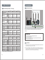
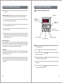
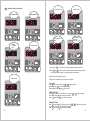
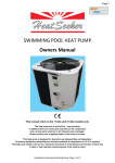
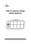
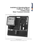
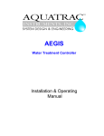
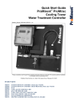
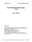
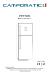
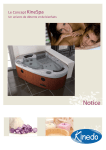
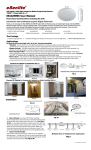
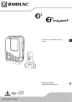
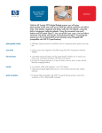
SWIMMING POOL HEAT PUMP
User Manual
INDEX
1. Introduction
2. Specifications
3. Installation
4. Initial Startup of the unit
1.Introduction
Thank you for using Heat Converter swimming pool heat pump for your pool heating,
it will heat your pool water and keep the constant temperature when ambient temperature
at +7℃ to 40℃.
In order to offer qualified, reliable and flexible heat pump unit to our customer, please
read this manual carefully before installing, operating and troubleshooting, then process
accordingly.
This manual includes all necessary information
5. Operation
6. Maintenance
!
ATTENTION
●
The heat pump unit must be installed by qualified technicians from after-sales
center or authorized distributor.
●
Operating and maintaining according to recommended time and frequency on
the manual.
●
Use only standard spare parts.
...01
1. Specifications
1.1
3. Installation
3.1 Installation illustration
Pool Heat Pump (Horizontal , EU design)
Models
* Capacity at +25℃
Heat Outpu t
Power
Consumption
XP09Hs
XP12Hs
XP18Hs
KW
8.7
12
18
KW
1.45
2.0
3.0
6
6
6
COP
* Capa city at +15℃
Heat Output
KW
6.45
9.0
13.5
Power
Consumption
KW
1.43
1.95
3.0
4.5
4.5
4.5
COP
*Power Supply
Voltage
V
220-240
220-240
220-240
Rate d Curr ent
A
6.7
9.3
13.9
Advised Fuse
A
20
20
35
m³
25-35
35-55
60-85
L/min
mm
100
140
170
50
50
50
WATER DATA
Advised pool volume
Advised water flux
Water pipe in-out spec
*General Data
Compressor
Rotary
Rotary
Rotary
dB(A)
36
37
42
dB(A)
Kpa
kg
47
48
54
15
15
16
1.2
1.3
2.3
1000/360/855
Air flow
*Condenser
Noise level(10m )
Noise level(1 m)
Water Pressure
Refri geran t
*Dimension & Weight
Net Dimension
Net Weight
mm
930/360/550
1000/360/620
kg
50
65
95
Packing Dimension
Gross Weight
mm
kg
1060/380/600
56
1065/380/670
72
1065/380/955
105
Water
Treatment
Horizontal
0.50m
mini
Pump
Filter
By-Pass
Hot Water To Pool
NOTE: The factory only provides the heat pump unit. The other items in the illustration
are necessary spare parts for the water system which are provided by users or
installers.
!
ATTENTION:
Please follow these steps when operating the first time :
1.Open valve and charge water
2.Make sure that the pump and the water-in pipe have been filled with water
3.Close the valve and start the unit
3.2
Installation
(1) The heat pump unit must be installed by professional technicians. otherwise unit
may be damaged or body injured, even dead
(2) The unit is designed for outdoor location with good ventilation. Recirculation of
cold discharge air back into evaporator coil will greatly reduce heating capacity and
efficiency of the unit, which will void the compressor warranty.
Above data is subject to modification without notice.
02...
...03
(3) The unit can be installed almost anywhere in the outdoors. To get a good
performance ,it needs to meet the three factors :
a) Good ventilation
b) Stable and reliable power supply
c) Recycled water system
The difference from gas water heater, it should not bring environmental pollution or
have the installing problems in-windy areas.
(11) It is required to increase the discharge pipe to prevent freezing in cold season, to
put T fitting and ball valve to facilitate changing the water in winter or emptying the
water out of system to prevent freezing when HP stop operating at the ambient
temperature below zero ,otherwise the unit may be damaged .
(12) It is suggested to install the quick adaptor in front of water in-out connection,
which could discharge water easily to prevent water freezing, and be convenient
for maintenance and service.
(4) The unit should not be installed in a limited air ventilation area ,or placed in a bush
where it will block the air inlet .These location deny the unit of a continuous source
of fresh air . When seasons changing , it may stick leaves on the evaporator coil ,
thereby reducing its efficiency and impact of its service life .
(13) When unit running ,there will be some condensation water discharged from the
bottom, please hold the drainage nozzle (accessory ) into the hole and clip well,
and then connect a pipe to drain the condensation water out.
(5) For indoor installation, please consult more instruction from technicians.
(14) If water pressure is over 10 KPA, or water flow rate is more than 11 cubic meters
through heat exchanger, it is necessary to install the by-pass pipe in water system.
(6) When install a bypass, it should be not exceed 30% of nominal flow rate .
3.3
(7) Must make Water level higher than the circulation pump location.
(8) Below picture show the minimum required distance on each side of pool heat pump
unit.
Air inlet
The location of chemical's instruction to your system is also
critical to the heater's life.
If an automatic chlorinator or brominates is used, it must be located downstream
of the heater.
A trap must be installed between the chlorinator and the heater to prevent chlorine
return into the heat pump. (See below pictures)
Pressure-type Chlorinator or Brominator
Check-valve
Filter
Chlorinator
Air outlet
P-trap
Water pump
Check-valve
In-line Chlorinator or Brominator
(9) Typically, the pool heat pump unit should be installed aside the pools, less than 7.5
meters distance.
(10) To get the best heat exchange of heat pump unit, it should be matched the normal
rate of water flow recommended in specification sheet.
04...
Disconnect: A disconnect means (circuit breaker, fused or un-fused switch) should be
located within sight of and readily accessible from the unit. This is common practice on
commercial and residential heat pumps. It prevents remotely-energizing unattended
equipment and permits turning off power at the unit while the unit is being serviced.
...05
4. Initial Startup of the unit
Note: Please make sure the water pump is running in circulation with adequate rate of
5. Operation Heating Only
5.1
The functions of LED wire controller
water flow.
Startup Procedure after Installation is completed, and please follow these steps:
(1) Turn on your filter pump ,check water leaks and verify flow of swimming pool
(2) Turn on the electrical power supply to the unit, then press the key ON/OFF of wire
controller, it should start in several seconds.
LED display
Press to
adjust the water
temperature
Operation mode
instruction
(3) After running a few minutes make sure the air ventilation from the side (top) of the
unit is cooler ( Between 5℃ and 10 ℃)
HE AT
(4) When turn off the filter pump, the unit should also turn off automatically, if not, then
adjust the flow switch
(5) Allow the unit and pool pump to run 24 hours per day until the water reaches the
desired temperature. When thetemperature reaches the setting value, the HP unit
will shut down, when the pool temperature drops more than 1℃, please restart (as
long as HP unit is running )
1
Press to turn
on and turn off the Unit
0
Press to set Timer on
Press to set the Time
Press to set Timer off
Water Flow Switch:
It is equipped with a flow switch for protecting the HP unit running with adequate water
flow rate .It will turn on when the pool pump runs and shut it off when the pump shuts off.
If the pool water level higher than 1 m above or below the heat pump's automatic
adjustment knob, your dealer may need to adjust its initial startup.
5.2
How to set operation parameter ( LED display show real time till HP
unit is power off. )
Time Delay:
(1) Long press "
HP unit should be equipped with a 3-minute built-in solid-state re-start delay protection.
Time delay control is an integral part of the circuit control, it can eliminate restart
cycling and contactor chatter.
(2) Under parameter setting, Press
parameter setting interface
The time delay will automatically restart the HP unit approximately 3 minutes after each
control circuit interruption. Even a brief power interruption will activate the solid state 3
minute restart delay and prevent the unit from the starting until the 3 minutes countdown
is completed.
" 5 seconds to enter operating parameter setting interface.
hold for 5 seconds to enter operating
(3) Under parameter setting, Press "
"again to start setting parameters from 0 to
A#, (see operation parameter table).
(4) Leave it 8 seconds, LED will display water in temperature (under running) or time
(until stops).
(5) Under current mode, press
or
whenever it is ON/OFF status.
06...
and
to modify the water setting temperature
...07
Parameter 0
To set the entering water
temp. under cooling mode
(8-35℃,default setting:
28℃)
HEAT
Parameter 6
Mode : 0 Cool 1 Heat and Cool
2 Heat and cool + auxiliary elec.
Heating 3 Heat
default setting : 3
Parameter 1
To set the entering water
temp. under heating mode
(15-35℃, default
setting:28℃)
MODE
MODE
HEAT
HEAT
1
1
1
0
0
1
Parameter 7
Mode selection of Electronic
expansion valve ( 0 to 1),
default setting 1 (auto)
MODE
HEAT
1
0
0
0
Note: Parameter 7 is only applied
for HP units with Electronic
expansion valve .
Parameter 2
Total working time of
compressor after frosting
(30-90MIN ,default
setting : 40MIN)
MODE
HEAT
1
MODE
HEAT
1
0
Parameter 4
Terms of Exit defrosting
function (2 to 30℃,
default setting 13℃)
MODE
HEAT
1
08...
0
Parameter 8
Heating target for superheat
(-15℃-15℃ ) default
setting :3℃
Parameter 3
Terms of Entry defrosting
function (-30℃ to 0℃,
default setting -7℃)
MODE
HEAT
1
0
HEAT
1
0
Parameter A
Manual adjustment steps of
electronic expansion valve
(18-94 ).defaulting setting :
70(*5)
Parameter 9
Cooling target for superheat
(-15℃-15℃ ),default
setting 10℃
Parameter 5
Time of Exit defrosting (1 to
12MIN, default setting 8MIN)
MODE
0
MODE
1
HEAT
0
MODE
1
HEAT
0
...09
5.3
How to know the current status?
Outlet water temp.
Inlet water temp.
MODE
MODE
HEAT
1
MODE
HEAT
1
0
Heating
Condenser
temp.
1
1
0
0
HEAT
0
Actual steps of
electronic
expansion valve
Cooling Condenser
temp.
Gas return temp.
HEAT
1
MODE
HEAT
MODE
MODE
Ambient temp.
Gas return temp.
MODE
HEAT
1
0
MODE
HEAT
1
1
0
(1) Long press“
HEAT
0
”5 seconds to enter operating parameter setting interface.
0
(2) Press
and
hold for 5 seconds to enter operating parameter setting interface.
You can check water -in/water-out /Condenser/ambient temperature.
(3) Mode can be changed while running.
Ambient temp.
(4) When the unit is switched off, current time is displayed.
Time setting:
Press
to set the time, and press
or
to adjust the time
After pressed the
again to store the new data.
When setting the time,
and
can not work.
1
0
TIMER ON SETTING
Press
to set the time for HP start to run ,and press
time.then,to press
again to store the new data.
When
lights, Press
to cancel the timer setting.
or
1
MODE
HEAT
to adjust starting
1
1
1
0
TIME OFF SETTING
Press
to set the time for HP stop running, press
running. then, press
againto store the new data.
When
lights, press
to cancel the timer setting.
0
or
to adjust the time of stop
0
0
10...
...11
5.4
RUNNING DATA SETTING
Remarks :
(1) When HP stop running in 30 seconds ,water pump will shut off automatically .
ATTENTION:
!
HP running parameters must be checked after installation and before first used.
(2) LED wire controller can operate the water pump after connected additional cable to
the pump device in the position of “PUMP” terminal accurately .
When HP is running, LED displays water inlet temperature
(3) It is necessary to put an extra 3-phase transfer device for 3 phase water pump
When HP is stopping, LED wire controller displays the actual time.
When HP running, the running mode ( cooling or heating) and water temp could be
changed. Other parameters only changeable when HP stopping.
6. Maintenance
(1)
Parameter
Meaning
Range
Default
Remarks
8-35℃
28℃
Adjustable
15-35℃
28℃
Adjustable
30-90MIN
40MIN
Adjustable
1
To set the entering water temp.
under cooling mode
To set the entering water temp.
under heating mode
2
Entry into defrosting time period
3
Terms of Entry defrosting function -30℃to 0℃
-7℃
Adjustable
4
Terms of Exit defrosting function
2 to 30℃
13℃
Adjustable
5
Time of Exit defrosting
1 to 12MIN
8MIN
Adjustable
6
Mode : 0 Cool 1 Heat and Cool
2 Heat and cool + auxiliary elec.
heating 3 Heat
0-3
3
Adjustable
7
Mode selection of Electronic
expansion valve
0-1
1 (auto)
Adjustable
8
Superheat for heating target
-15℃-15℃
3℃
Adjustable
9
Superheat for cooling target
-15℃-15℃
10℃
Adjustable
A
Manual adjustment steps of
electronic expansion valve
18-94
70
0
b
Inlet water temperature
-9-99℃
C
Outlet water temperature
-9-99℃
d
Condenser temperature
under heating mode
-9-99℃
E
Gas return temperature
-9-99℃
Ambient temperature
-9-99℃
F
G
H
12...
Condenser temperature
under Cooling mode
Actual steps of electronic
expansion valve
-9-99℃
N*5
Adjustable
You should check the water supply system regularly to avoid the air entering
the system and occurrence of low water flow, because it would reduce the
performance and reliability of HP unit.
(2) Clean your pools and filtration system regularly to avoid the damage of the unit
as a result of the dirty of clogged filter.
(3) Keep the HP unit dry, clean, well-ventilated and always clean side of the heat
exchanger which can maintain a good heat exchange and energy saving.
(4) Only a qualified service technician is allowed to operate pressure of the
refrigeration system.
(5) Check power cable connection, if heat pump start to operate abnormally, you
should turn it off and contact with qualified technicians.
(6) You should discharge the water from water pump and other water system, to
prevent from the freezing damage in winter seasons.
(7) You should discharge the water from bottom of water pump if HP unit will stop
running for a long time. In another way, you should check the units thoroughly
and fill the system with water fully before the unit start to run again.
Exact testing
by value
Exact testing
by value
Exact testing
by value
Exact testing
by value
Exact testing
by value
Exact testing
by value
Exact testing
by value
...13