1
Nexus® 1500 Meter Quick Start Guide
Mechanical Installation
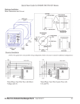
1. Slide the meter into the panel’s cut-out. (See the diagram shown
on the right. You can use either an octagonal or a rectangular cut-out.)
2. From the back of the panel, slide the 4 Mounting Brackets into the
grooves on the top and bottom of the meter housing - 2 fit on the top
and 2 fit on the bottom.
3. Snap the Mounting Brackets into place.
4. Secure the meter to the panel with lock washer and a #8 screw
in each of the 4 mounting brackets.
5. Tighten the screws with a #2 Philips screwdriver.
Do not over-tighten.
Mounting
Bracket
Rectangular Cut-out Dimensions
Electrical Wiring Diagrams
Grooves
#8
Screw
WYE or DELTA Direct 3 Phase, 4-wire
WYE or DELTA with PTs 3 Phase, 4-wire
DELTA Direct 3 Phase, 3-wire
DELTA with PTs, 3 Phase, 3-wire
NOTE: See the meter’s Installation and Operation Manual for additional wiring configurations.
e Electro Industries/GaugeTech
Doc # E154702 V.1.02
Q-1
Programming the Nexus® 1500 Meter Using the USB Virtual Com Port
NOTES:
• Before using the USB Virtual Com port for the first time, see Appendix A of the Nexus® 1500 Meter Installation and
Operation Manual that came with your meter, for instructions on configuring it.
• You can view detailed meter programming instructions by clicking Help>Contents from the Communicator EXT
Main screen.
Connecting to the Nexus® 1500 Meter
1. Open Communicator EXT software. (This software is on the
enclosed CD.)
2. Click the Connect icon on the Tool Bar. You will see the Connect
screen, shown on the right.
3. Click Serial Port.
4. Select Baud rate of 115200.
5. Select the Port that is the USB virtual Com port.
6. Click Connect. You will see the Device Status screen.
7. Click OK. You will see the Main Communicator EXT screen.
Configuring the Nexus® 1500 Meter
Click the Profile icon on the Tool Bar. You will see the Device Profile screen.
NOTE: Instructions for a few basic settings are given in this Quick Start Guide. For more information, click
Help>Contents from the Title Bar of the Communicator EXT Main screen, to view the Communicator EXT 3.0
User’s Manual.
CT, PT Ratios and System Hookup
1. From the Device Profile screen, double-click General
Settings>CT, PT Ratios and System Hookup. The current
settings are shown on the screen.
2. Double-click one of the settings to open the CT and PT Ratios
screen, shown on the right.
3. You can enter CT and PT Ratios and select Hookup and
Frequency from the pull-down menu.
4. Click OK to close the screen. Click Update Device from the
Device Profile screen to save your settings.
Communication Settings
1. From the Device Profile screen, doubleclick General Settings>Communications.
The current settings for the meter’s Ports are
shown on the screen.
2. Double-click one of the Port settings to open
the Communications screen, shown on the
right.
3. You can configure the settings for all four
Communication Ports, as well as the two
Network Cards. Click Help to view
instructions for configuring these settings.
4. Click OK to close the screen. Click Update
Device from the Device Profile screen to
save your settings.
NOTE: You can also use the standard or
optional Ethernet ports, the optional RS485
ports, or the ANSI optical port to connect to and
configure the Nexus® 1500 meter.
e Electro Industries/GaugeTech
Doc # E154702 V.1.02
Q-2
020410