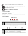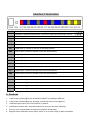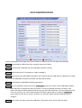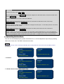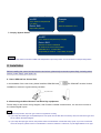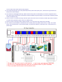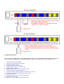
1
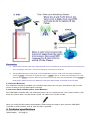
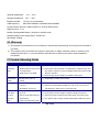
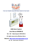
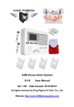
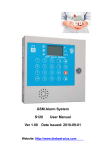
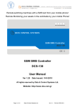
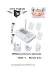
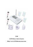
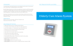
A Professional GSM Alarm System designer and manufacturer!
GSM SMS Controller System &GSM House Alarm System&
GSM Telemetry Units & GSM GPRS Logging System
Http://www.GSMalarmsystem.com [email protected]
Remote switching machines with a SMS text from your mobile phone!
Remote Monitoring your assets in the worldwide by your mobile Phone!
GSM SMS Controller
GSM SMS Alarm Unit
S130 S140 S150
User Manual
Ver 1.20
Date Issued: 2010-09-14
All rights reserved by King Pigeon Hi-Tech. Co., Ltd.
Website: Http://www.GSMalarmsystem.com
Page 1 of 14
King Pigeon Hi-Tech. Co., Ltd.
Page 1 of 14 Ver 1.2
File No.:KPS13011
A Professional GSM Alarm System designer and manufacturer!
GSM SMS Controller System &GSM House Alarm System&
GSM Telemetry Units & GSM GPRS Logging System
Http://www.GSMalarmsystem.com [email protected]
Table of contents
1.
Brief introduction ----------------------------------------------------------------------------3
2.
Safety Directions ----------------------------------------------------------------------------3
3.
Standard Packing list -----------------------------------------------------------------------4
4.
Physical Layout ------------------------------------------------------------------------------4
5.
Features ---------------------------------------------------------------------------------------5
6.
Settings ----------------------------------------------------------------------------------------6
7.
Operation --------------------------------------------------------------------------------------8
8.
Installation ------------------------------------------------------------------------------------9
9.
Technical specifications
10.
Quality Warranty ---------------------------------------------------------------------------14
11.
Trouble Shooting Guide------------------------------------------------------------------14
----------------------------------------------------------------13
This handbook has been designed as a guide to the installation and operation of S130,S140,S150 GSM SMS Controllers.
Statements contained in the handbook are general guidelines only and in no way are designed to supersede the instructions
contained with other products.
We recommend that the advice of a registered electrician be sought before any Installation work commences.
King Pigeon Hi-Tech.Co., Ltd, its employees and distributors, accept no liability for any loss or damage including
consequential damage due to reliance on any material contained in this handbook.
King Pigeon Hi-Tech.Co., Ltd, its employees and distributors, accept no liability for GSM Network upgrading or SIMCard
upgrading due to the technology specifications contained in this handbook.
Model List
Model No.
Differences
S130
2 Digital inputs, 1 Alarm Link relay output, 1 separate relay output for SMS Commands.
S140
4 Digital inputs, 1 Alarm Link relay output, 1 separate relay output for SMS Commands.
S150
8 Digital inputs, 1 Alarm Link relay output, 1 separate relay output for SMS Commands.
SMS Command List
SMS COMMAND
Functions & Actions
AA
To arm the system, in this case, any sensor triggered will alarm.
BB
To disarm the system, in this case, any sensor triggered will not alarm.
CC
To switch ON the separate relay output
DD
To switch OFF the separate relay output
EE
Inquiry the GSM SMS Controller Status
*The commands should plus Password, the format is Password+SMS Command. i.e.: if the password is 1234, then you
can send 1234AA to arm, 1234BB to disarm.
Page 2 of 14
King Pigeon Hi-Tech. Co., Ltd.
Page 2 of 14 Ver 1.2
File No.:KPS13011
A Professional GSM Alarm System designer and manufacturer!
GSM SMS Controller System &GSM House Alarm System&
GSM Telemetry Units & GSM GPRS Logging System
Http://www.GSMalarmsystem.com [email protected]
1. Brief introduction
The GSM SMS Controller is a very simple device which can be used for authorized door access, controlling
gates, switching of remote equipments, car parking systems. Actually the GSM SMS Controller can be used in
places which require turning ON/OFF your system, machines, equipments remotely with a SMS text from your
mobile phone and protect your assets.
Moreover, the GSM SMS Controller with multi-digital inputs for digital inputs, when any one of the inputs
triggered, will start the siren or switch on the light automatically. in the meanwhile, the GSM SMS Controller will
send SMS Alert the to owners immediately. This is very useful if you need protect your assets with low cost
solution.
The GSM SMS Controller suitable for below applications:
1.
2.
3.
4.
5.
6.
7.
8.
9.
10.
11.
12.
13.
14.
15.
16.
17.
18.
19.
Security Alarm System applications;
Supervision and monitoring alarm systems;
Automatic monitoring system;
Vending Machines security protection;
Pumping Stations, Tanks, Oil or Water levels;
Buildings and Real Estate;
Weather Stations;
River Monitoring and Flood Control;
Oil and gas pipelines;
Corrosion protection
Temperatures, water leakage applications;
Wellheads, boat, vehicle;
Energy saving, street lights control system;
Valve controls;
Transformer stations;
Unmanned machine rooms;
Control room application;
Automation System, M2M;
GSM Access Control System, GSM Gate Opener, etc.
2.Safety Directions
Safe Startup
Do not use GSM SMS Controller when using GSM equipment is prohibited or might bring
disturbance or danger.
Interference
All wireless equipment might interfere network signals of GSM SMS Controller and influence its
performance.
Avoid Use at Gas Station
Do not use GSM SMS Controller at a gas station. Power off GSM SMS Controller when it near
fuels or chemicals.
Page 3 of 14
King Pigeon Hi-Tech. Co., Ltd.
Page 3 of 14 Ver 1.2
File No.:KPS13011
A Professional GSM Alarm System designer and manufacturer!
GSM SMS Controller System &GSM House Alarm System&
GSM Telemetry Units & GSM GPRS Logging System
Http://www.GSMalarmsystem.com [email protected]
Power it off near Blasting Places
Please follow relevant restrictive regulations. Avoid using the device in blasting places.
Reasonable Use
Please install the product at suitable places as described in the product documentation. Avoid
signal shielded by covering the mainframe.
Use Qualified Maintenance Service
Maintenance can be carried out only by qualified maintainer.
3. Standard Packing List
Control Unit X1, GSM ANT X1, User Manual X1(CD), Connectors, AC/DC Adaptor X1.
Optional Accessories: (Wired Sensors)
PIR Motion Sensor, Glass Break Sensor, Magnetic Window Sensor, Temperature Sensor, Infrared Beam
Fence, Vibration sensor, Water level sensor, Siren, etc.
4. Physical Layout
4.1 Control Unit physical layout
LED Instruction
GSM
GSM Module indicator, registering will quickly flick, registered successful will slowly flick.
RELAY
Output relay indicator, when any output relay closed, it will be on; when relay opened, will be off.
STATUS
Arm Indicator, on is armed, off is disarmed;
Alarm
Alarm Indicator, on is alarming, off is normally;
Interface 1 Instruction
MIC
For listening in the sounds around the GSM SMS Controllers while alarm, the Microphone is
needn’t power, is the same type for the computer.
SPK
For two way voice communication. When the authorized number dial in, the unit will check the
incoming number, if matched, then can create two-way voice communication.
GSM ANT
Connect the GSM ANT, if the GSM signal is not strong, then please change the 3dB GSM ANT.
USB
Connect to the computer, for setup the unit parameters.
Page 4 of 14
King Pigeon Hi-Tech. Co., Ltd.
Page 4 of 14 Ver 1.2
File No.:KPS13011
A Professional GSM Alarm System designer and manufacturer!
GSM SMS Controller System &GSM House Alarm System&
GSM Telemetry Units & GSM GPRS Logging System
Http://www.GSMalarmsystem.com [email protected]
Interface 2 Instruction
POWER
External Power Connector, Connect to 2A@12V DC power through AC/DC Adaptor.
SIREN
+12V
Will start for 60seconds when alarm. The siren or strobe siren should be <12V DC.
+12VDC@1A power output for wired detectors.
IN1
Digital input 1, connect to one wire of the wired Detector.
GND
Ground point, connect to another wire of the wired Detector or -12VDC.
IN2
Digital input 2, connect to one wire of the wired Detector.
IN3
Digital input 3, connect to one wire of the wired Detector.
GND
IN4
+12V
IN5
GND
Ground point, connect to another wire of the wired Detector.
Digital input 4, connect to one wire of the wired Detector.
+12VDC@1A power output for wired detectors.
Digital input 5, connect to one wire of the wired Detector.
Ground point, connect to another wire of the wired Detector or -12VDC.
IN6
Digital input 6, connect to one wire of the wired Detector.
IN7
Digital input7, connect to another wire of the wired Detector.
GND
Ground point, connect to another wire of the wired Detector.
IN8
Digital input 8, connect to one wire of the wired Detector.
R1+
Built in 240VAC@3A rated relay output, connect to the device positive electrode.
R1-
Built in 240VAC@3A rated relay output, connect to the device negative electrode.
R2+
Built in 240VAC@3A rated relay output, connect to the device positive pole.
R2-
Built in 240VAC@3A rated relay output, connect to the device negative electrode.
5. Features
1. 1 relay output (240VAC@3A) can be switched ON/OFF by sending a SMS text;
2. 1 relay output (240VAC@3A) can be switch on 4minutes if any inputs triggered;
3.
2/4/8 Alarm logic inputs, NC or NO and EOL is optional;
4. 3 SMS Alert numbers and 5 auto-dial numbers can accept to the alarm message;
5. Two-way voice communication by external microphone and speaker;
6. Supports armed, disarmed, inquiry status, switch on or off relay output by SMS Commands;
Page 5 of 14
King Pigeon Hi-Tech. Co., Ltd.
Page 5 of 14 Ver 1.2
File No.:KPS13011
A Professional GSM Alarm System designer and manufacturer!
GSM SMS Controller System &GSM House Alarm System&
GSM Telemetry Units & GSM GPRS Logging System
Http://www.GSMalarmsystem.com [email protected]
7. Password protected, prevents unauthorized user;
8. Can be set up and programmed from PC Programmer by USB cable;
9. Time stamped alarm messages.
10. Backup rechargeable battery inside, can work for 24hours when power off.
11. Can be operated from anywhere, no distance limit;
12. Based on GSM Network, applied to many applications.
6. Settings
The GSM SMS Controller is for user-friendly design. The user can setup it by the PC programmer through USB
cable. The GSM SMS Controller can not setup by SMS Commands.
Tips!
1)
In order to forbidden the intruders power off the unit, we equipped the power switch inside, it is nearby the SIMCard socket,
please pay attention to it, and don’t tell others of this. Turn it towards inside is off, turn it towards outside is on. And when setup
the unit, please put the Setting switch to SET position, after setup, switch it to WORK Position. Please see below photo.
2)
Please insert the SIMCard firstly, and install the GSM Antenna, please power on to check the LEDs can work or not, then
power off it before you program it by PC Programmer.
3)
The default password is 1234, you can modify it by enter the new password in the PC Programmer.
4)
Two way communication: While the authorized users incoming call, the GSM SMS Controller unit will automatically answer the
call, then the two-way voice communication will be created. If you want to test the two way voice communication, please make
sure the other phone is away from the GSM SMS Controller unit at least 500meters. Otherwise, the near-cross will make lots
of noise interference.
Page 6 of 14
King Pigeon Hi-Tech. Co., Ltd.
Page 6 of 14 Ver 1.2
File No.:KPS13011
A Professional GSM Alarm System designer and manufacturer!
GSM SMS Controller System &GSM House Alarm System&
GSM Telemetry Units & GSM GPRS Logging System
Http://www.GSMalarmsystem.com [email protected]
The PC Programmer Interface
Please following the below steps one by one to setup it, otherwise you can not setup it successfully.
Step1: Please install the USB Driver to the computer from the CD firstly;
Step2: Please insert the SIMCard into the GSM SMS Controller carefully;
Step3: Please running the PC Programmer, needn’t installed it;
Step4: Please connect the GSM SMS Controller to the computer through USB cable, but please don’t switch
on the GSM SMS Controller, otherwise, the setup will be failure;
Step5: Please setup the GSM SMS Controller parameters;
Step6: After you finished the setup, then press “Download” button then switch on the GSM SMS controller,
after 2Seconds, it will alert the Setup successful. If it hasn’t prompted the setup successful, then
means the setup is failure, please check the Com port and USB connection. You can change the Com
Port to try it one by one, if the Communication LED sign is green after you press the “Download” ,
then means the Com port is correct, otherwise, it is incorrect, please use the dropdown menu to
change it.
Step 7: Power off the unit then remove the USB cable. Then power on the Unit to finish the setup.
Page 7 of 14
King Pigeon Hi-Tech. Co., Ltd.
Page 7 of 14 Ver 1.2
File No.:KPS13011
A Professional GSM Alarm System designer and manufacturer!
GSM SMS Controller System &GSM House Alarm System&
GSM Telemetry Units & GSM GPRS Logging System
Http://www.GSMalarmsystem.com [email protected]
If it hasn’t prompted the setup successful, then means the setup is failure, please check the Com port and USB
connection, then try to repeat the Step1~Step6 again.
Items Description Alarm Target Ph. No.
Please add the country code, e.g.: +86 or 0086 in China. When alarm, the unit will call these numbers one by one after sent out SMS Alarm message. Please see below tips. SMS Alert Numbers
Please add the country code, e.g.:+86 or 0086 in China. When alarm, the unit will send related Digital Input SMS Alert Content to these numbers one by one firstly. Digital Input SMS
Alert Contents
These words or sentences will be sent to the SMS Alert Numbers once the related inputs triggered. Max. Characters: 34. Sound Alarm
Power Down Alert
Select it to switch on the siren for 60 seconds when Alarm occurrence. Select it to send SMS alert when external AC Power failure more than 30 minutes. GSM Jammer
Select it to make siren sound and alarm‐link output relay close for 4minutes when the unit detected no GSM signal for more than 90 seconds.(Usually please don’t enable it.) Arm
Select it to set the unit to arm mode once power on. in this case, any sensor triggered will alarm. The system will send out the preset SMS text to SMS alert numbers, and dial the Alarm target phone numbers one by one, in the meantime, the siren will sound 1 minutes and the alarm‐link output relay will switch on 4 minutes. Otherwise, the system will in disarmed mode after power on. Password
Report Time
To verify the SMS commands from the authorized users and modify new password. Fill it to setup the Report time gap, Range: 0~240Hours. The unit will automatically send its status to SMS alert numbers according to this setting. Alarm Delay Time
To setup the delay time after any sensor triggered. The range is 0~90Seconds. Digital Input Type
NC: Normal Close; NO: Normal Open; EOL: End of Line, Means must be connection in series with a 2.2K resistor between the GSM SMS controller and digital detector. Com Port
Select the Com port to communicate between GSM SMS Controller and Computer. Download
Download the settings from computer to GSM SMS Controller. Upload
Upload the settings from GSM SMS Controller to computer. Save
Save the settings to computer. Read
Read the settings from the Saved file in the computer. Stop
Stop the communication between the computer and GSM Controller. Notice: 1. In some GSM operators they use different SMS protocols, if the unit can’t return the SMS confirmation is
normally. It is not product problem. Also, you can try to add the country code before the number, see the
below settings:
Page 8 of 14
King Pigeon Hi-Tech. Co., Ltd.
Page 8 of 14 Ver 1.2
File No.:KPS13011
A Professional GSM Alarm System designer and manufacturer!
GSM SMS Controller System &GSM House Alarm System&
GSM Telemetry Units & GSM GPRS Logging System
Http://www.GSMalarmsystem.com [email protected]
For example:
In China, the country code is +86, or 0086.
The user cell phone number is 13570810254 and has been assigned as a SMS Alert number, the simcard number in the
panel is 13512345678.
Problem 1: Alarm but the user hasn’t received the SMS Alert.
Solution: Please plus the country code while you setup the 13570810254 as SMS Alert number, means setup
+8613570810254 to instead of the 13570810254.
Problem 2: The user number can receive the SMS Alert message from alarm panel, but the alarm panel can not receive
the commands from the user number.
Solution: Please add country code to the SIMCard number in the alarm panel. Means send sms commands to
+8613512345678 to instead of 13512345678.
Solution 3: When you use cell phone dial another one, what number it will be displayed then you can set the displayed
number as dial numbers; when you use cell phone send SMS to another cell phone, what number it will be displayed then
you can set the displayed number as SMS Alert number, just use the “+” to replace the “00”, also, you can try the “00”.
7. Operating Instructions
The User can Arm/Disarm/Inquriy system status/Switch on or off the independent output relay by sending
SMS to the Control unit. The SMS Commands are below:
Notice:
The system will carry out the commands immediately (with no delay) after the Control Unit receive this SMS command.
7.1 Armed
xxxxAA
Example
“xxxx” stands for the password
1234AA
(1-4 digits).
Return SMS
When the Password is 1234
Armed Mode activated.
7.2 Disarm
xxxxBB
Example
“xxxx” stands for the password
1111BB
(1-4 digits).
Return SMS
When the Password is 1111
System deactivated.
7.3 Switch On the independent output relay
xxxxCC
Example
“xxxx” stands for the password
1111CC
(1-4 digits).
Return SMS
When the Password is 1111
Output Relay Closed.
Page 9 of 14
King Pigeon Hi-Tech. Co., Ltd.
Page 9 of 14 Ver 1.2
File No.:KPS13011
A Professional GSM Alarm System designer and manufacturer!
GSM SMS Controller System &GSM House Alarm System&
GSM Telemetry Units & GSM GPRS Logging System
Http://www.GSMalarmsystem.com [email protected]
7.4 Switch OFF the independent output relay
xxxxDD
Example
“xxxx” stands for the password
1111DD
(1-4 digits).
Return SMS
When the Password is 1111
Output Relay Opened.
7.5 Inquiry System Status
xxxxEE
“xxxx” stands for the password (1-4 digits).
Return SMS
Armed or At House or Disarmed
AC Power is Ok or AC Power is failed
GSM Value is 17 or other value
Output Relay is Closed or
Output Relay is opened
Notice:
The Output relay status in the Return SMS is the independent output relay status. It is not the alarm link Output Relay Status.
8. Installation
Before installing the control unit and sensors and sirens, please help to test the system firstly, including wired
sensor, power supply, gsm signal, etc.
8.1 Insert SIMcard into Control Unit
In the backside of the control unit, please install the GSM SIM card
. The GSM ANT must be Vertical
installation to ensure it in good working condition.
8.2 Connecting the Wired Sensors and Electricity equipments
Please help to see below wiring diagram, then fixed the related wired sensors, the sensors connect to
the related digital inputs.
Tips!
1) Please setup the NC, NO, EOL type in the PC Programmer correctly;
2) If you setup the Nodes type as NC(Default),the no-use inputs must be with short-circuited by wires, and the sensor type must
be NC. Please see below diagram.
3) If you setup the input type as EOL, then please contact a 2.2K Resistor in series with every inputs, if you don’t connect the
sensor to the inputs, please connect a 2.2K Resistor in series to instead of it . Moreover, only the digital detector is NC type
Page 10 of 14
King Pigeon Hi-Tech. Co., Ltd.
Page 10 of 14 Ver 1.2
File No.:KPS13011
A Professional GSM Alarm System designer and manufacturer!
GSM SMS Controller System &GSM House Alarm System&
GSM Telemetry Units & GSM GPRS Logging System
Http://www.GSMalarmsystem.com [email protected]
can use in EOL mode. Please see the below diagram.
4) If you setup the input type as NO, then please keep the two points of the inputs by free , and the sensor type must be NO.
Please see the below diagram.
5) The Unit built-in 240VAC@3A rated relay. Please make sure the power cord rated while you connect to equipment device.
also, please make sure the power consumption is less than 250W for long time working. If you need heavy equipment, please
connect an additional relay ;
6) The R1+ and R1- is for alarm-link output, when the system alarm, will close for 4 minutes, the rated output power is 700W. If
you need heavily equipment, please connect an additional relay .
7) The R2+ and R2- is the relay output for SMS Command, CC is close, DD is open, EE is inquiry the status.
8) The +12VDC is for the Detectors, if the detectors need 12VDC power, then please contact it to the +12VDC. The 12VDC
power is from external power, not from backup battery. So please note: When AC power failure, the +12VDC point will no
power supply.
Page 11 of 14
King Pigeon Hi-Tech. Co., Ltd.
Page 11 of 14 Ver 1.2
File No.:KPS13011
A Professional GSM Alarm System designer and manufacturer!
GSM SMS Controller System &GSM House Alarm System&
GSM Telemetry Units & GSM GPRS Logging System
Http://www.GSMalarmsystem.com [email protected]
8.3 Typical application
One of the typical application of the GSM SMS Controller is for automatically water tank monitoring and
control solution. Please help to see below diagram. Also it can use to lots of other solutions. E.g.:
1.
2.
3.
4.
5.
6.
7.
8.
9.
10.
11.
12.
13.
14.
Security Alarm System applications;
Supervision and monitoring alarm systems;
Automatic monitoring system;
Vending Machines security protection;
Pumping Stations, Tanks, Oil or Water levels;
Buildings and Real Estate;
Weather Stations, River Monitoring and Flood Control;
Oil and gas pipelines, Corrosion protection
Temperatures, water leakage applications, Wellheads, boat, vehicle;
Energy saving, street lights control system, Valve controls;
Transformer stations;
Unmanned machine rooms, Control room application;
Automation System, M2M;
GSM Access Control System, GSM Gate Opener, etc.
Page 12 of 14
King Pigeon Hi-Tech. Co., Ltd.
Page 12 of 14 Ver 1.2
File No.:KPS13011
A Professional GSM Alarm System designer and manufacturer!
GSM SMS Controller System &GSM House Alarm System&
GSM Telemetry Units & GSM GPRS Logging System
Http://www.GSMalarmsystem.com [email protected]
Explanation:
1)
Use the water level sensor (WL-03) to detect the water level, it can detect the low level and high level, two wires for low
level, connecting to S130 input 1, two wires for high level, connecting to S130 input 2.
2)
Set the SIMCard Number in B side S130 as the first SMS Alarm number in A side S130, and modify the SMS Alert
content as 1234CC (1234 stands for password) to input 1, 1234DD to input 2. So when Low level detected, the A side
S130 will send 1234CC command to B side S130 to switch ON the Pump, when high level detected, will send 1234DD to
B side S130 to Switch OFF the Pump. Means the A side alarm SMS message as the B side S130 Command.
8.3 Install the Mainframe
The mainframe should be installed in the position that person can not get it, and there’re with a power
source as well as enough GSM signal coverage.
8.4 Install the Speak and Microphone to the Mainframe
The GSM SMS Controller allow the authorized users call in to create two way voice communication, also,
when the system alarm, the authorized number can listen in the on-site sounds.
While you install the Microphone and Speaker, please make sure keep it away from the GSM SMS
Controller at least 1meters, and far from the siren if possible.
9. Technical specifications
Rated Voltage:
12VDC@ 2A
Page 13 of 14
King Pigeon Hi-Tech. Co., Ltd.
Page 13 of 14 Ver 1.2
File No.:KPS13011
A Professional GSM Alarm System designer and manufacturer!
GSM SMS Controller System &GSM House Alarm System&
GSM Telemetry Units & GSM GPRS Logging System
Http://www.GSMalarmsystem.com [email protected]
Working temperature:
-10℃~+60℃
Storage temperature:
-20℃~+60℃
Relative humidity:
10-90%, No condensation
GSM frequency:
900/1800/1900MHz or 850/900/1800/1900Mhz
Communication protocol: GSM PHASE 2/2+ (include data service)
Digital inputs: 2 / 4 / 8
Backup Rechargeable Battery: 24Hours in standby mode.
Related Voltage of the Output Relay: 3A/240V AC
Net Weight: 0.60Kg
10. Warranty
1) This system is warranted to be free of defects in material and workmanship for one year from the date of
purchase.
2) This warranty does not extend to any defect, malfunction or failure caused by abuse or misuse by the
Operating Instructions. In no event shall the manufacturer be liable for any alarm system altered by
purchasers.
11.Trouble Shooting Guide
PROBLEM
CAUSE
GSM Module 1) Backup battery with low voltage;
initialization
GSM Module connection loose
failed
in transportation;
POSSIBLE SOLUTION
1) Please contact the AC Power;
2) Please help to take the panel to a mobile phone repairmen store, and
then ask the engineer to check the GSM Module socket and the GSM
2) GSM Signal is too weak.
Module connection;
3) Please change another position to install the alarm panel.
Automatically
Restart
1) Backup battery with low
voltage.
False Alarm
1) PIR Motion sensor installation
2) NC/NO/EOL is incorrect.
Alarm without
SMS /Dial/
No action
after send
1) Please see the PIR Motion sensor installation user manual carefully;
2) Please check the detector NC/NO type, and you’re sure connect a
incorrect;
SMS
1) Please help to contact the AC Power.
1) GSM Operator communication
2.2K Resistor in series in the un-use input ports.
1) Please setup the SMS Alert Numbers;
2) Please help to see the sample of setup the telephone numbers;
protocol;
2) Haven’t setup SMS Alert/Auto
3) Please check the commands with CAPS LOCK and correct format.
4) Also, please help to change another GSM Operator SIMCard to test it.
dial Numbers.
3) Caps Lock letters in the SMS.
The End!
Any questions please help to contact us feel free.
Email Us: [email protected]
Http://www.GSMalarmsystem.com
Page 14 of 14
King Pigeon Hi-Tech. Co., Ltd.
Http://www.KingPigeon.com.cn
Page 14 of 14 Ver 1.2
File No.:KPS13011