1
ELSEMA
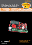
GSM Receiver with relay output, GSM-4000
GSM-4000
GSM, SMS controller for automatic switching of devices.
Features
Switches relay with SMS messages.
Sends SMS message when inputs are activated.
Supports NO or NC inputs.
Easily programmed with user friendly computer software.
Operates from anywhere if GSM network is available.
Unlimited range!
Ignores unauthorised numbers
4 digital inputs for sensors or switches.
Built-in rechargeable back-up battery. Lasts for up to 24hours.
Secure. Password protected
12 Volts DC power pack included
Application
Automatic switching pumps, irrigation systems.
Security alarm, fire alarm, temperature monitoring.
Endless applications.
Description
The GSM-4000 has 4 inputs which can be set as NO, NC or Disabled. The GSM-4000 can be programmed to
send an SMS message when any of the inputs are triggered or recovered. There are 2 relay outputs. Relay 1 can
be programmed to switch "On" when any of the inputs are triggered and relay 2 can be switched "On" by SMS
message. The GSM-4000 also has a microphone (mic) and a speaker connection. It can be programmed so that
when an input is triggered, the GSM-4000 makes a call to the programmed numbers and create a 2-way voice
communication.
All configurations are done through a user friendly computer software. The GSM-4000 connects to the
computer through a standard USB connection.
The GSM-4000 works on GSM network therefore the receiver can be activated from anywhere in the country
where GSM network is available. For example you can open your gate or switch on your kitchen lights in
Sydney from Melbourne by sending a simple SMS message.
The GSM unit can be armed and disarmed by simple SMS message.
12 Volts DC Power Pack Included
Page 1
www.elsema.com
ELSEMA
GSM Receiver with relay output, GSM-4000
Technical Data
Power Source
12 Volts DC
GSM Frequency
Output
900/1800MHz
Common (C) and Normally Open (NO) relay outputs rated at 3A, 240VAC.
Shipping Weight
Dimensions
690 grams
155 x 95 x 28mm.
Safety Instruction
Safe startup
Do not use the GSM-4000 in places where GSM equipment is prohibited or might bring
disturbance or danger
Interference
Wireless equipment might interfere GSM network signals of the GSM-4000 and influence its
performance.
Avoid using at Gas Stations
Do not use GSM-4000 at a gas station. Power off the unit when near fuels or chemicals
Avoid using near blasting areas
Please follow relevant restrictive regulations. Avoid using the device in blasting places.
Reasonable Use
Please install the product at a suitable place as described in this manual. Avoid signal shielding by
covering the mainframe.
Maintenance
All wiring and maintenance should be carried out only by qualified maintenance personnel.
Page 2
www.elsema.com
ELSEMA
GSM Receiver with relay output, GSM-4000
Setup Instructions
1. The GSM-4000 is easily setup using the computer software provided.
2. For added security, there is and "On-Off" switch and a "setup" and "normal operation" switch. When the
unit is connected to the computer please make sure that the switch is in setup position.
3. Make sure that after you have finished setting up the unit, slide the switch to normal operation mode.
4. The default password is 1234. It can be easily changed by the computer software
5. A two-way voice communication is possible when external mic and speaker is connected to the unit. A
two-way voice communication established when:
a.) An authorised user makes a call to the unit or
b.) The unit is programmed to dial a number when an input is triggered.
6. The backup battery inside the GSM-4000 does not control the output relays. If the supply to the unit is
switched "Off" the 2 output relays will switch Off as well.
7. The GSM-4000 can only handle one alarm event at a time.
Connections and Display
LED indicators
Network indicator:
GSM
Flashing fast- Searching for a network.
Flashing slowly - Successfully connected to the network
Relay On
Armed
Alarm
Indicates switching of relay 1 or relay 2
"On" Unit is armed
"Off" Unit is disarmed
Alarm is activated.
Page 3
www.elsema.com
ELSEMA
GSM Receiver with relay output, GSM-4000
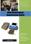
Antenna, USB and optional microphone and speaker
MIC
3.5mm socket for external microphone for 2-way communication. (optional)
SPK
3.5mm socket for external speaker for 2-way communication. (optional)
GSM Ant
USB
Connect the GSM antenna provided. Use a high gain antenna if signal is poor.
Connect to your COMPUTER for setup using the GSM-4000 software.
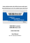
Inputs and Outputs
Connect the 12VDC power pack supplied with the GSM-4000
Supply
Siren
+12VDC
Input 1
Gnd
If siren is used, please make sure that the power supply is big
enough to supply the GSM unit and the siren
Siren or strobe light output. This outputs will activate siren or
strobe light when alarm is activated. (optional)
12VDC to supply sensors
Digital input 1. Connect sensors, push buttons, switches etc. If it is not used, please
set it as Disabled in the software
Ground
Input 2
Digital input 1. Connect sensors, push buttons, switches etc. If it is not used, please
set it as Disabled in the software
Input 3
Digital input 1. Connect sensors, push buttons, switches etc. If it is not used, please
set it as Disabled in the software
Gnd
Input 4
Ground
Digital input 1. Connect sensors, push buttons, switches etc. If it is not used, please
set it as Disabled in the software
+12VDC
12VDC to supply sensors
Relay 1
Activates when any of the inputs are triggered. Rated at 3A at 240VAC
Relay 2
Activates by SMS message. Rated at 3A at 240VAC
Page 4
www.elsema.com
ELSEMA
GSM Receiver with relay output, GSM-4000
SMS Commands List
SMS Commands
Function
AA
Arm the GSM-4000
BB
Disarm the GSM-4000
CC
Switch relay 2 "ON"
DD
Switch relay 2 "OFF"
EE
GSM-4000 status
Please note that all SMS commands should be in upper case and is preceded by a password. Below is an
example: (password is 1234)
1234AA
Correct
1234aa
Incorrect
The user can arm, disarm, switch relay 2 "On" and "Off" and check the status of the unit by sending SMS
messages.
•
•
•
•
•
ARM the Unit
SMS Command
PwdAA ("Pwd" is your 4-digit password)
Return SMS
Armed
DISARM the Unit
SMS Command
PwdBB ("Pwd" is your 4-digit password)
Return SMS
Disarmed
Switch relay 2 "ON"
SMS Command
PwdCC ("Pwd" is your 4-digit password)
Return SMS
Output Relay Closed
Switch relay 2 "Off"
SMS Command
PwdDD ("Pwd" is your 4-digit password)
Return SMS
Output Relay Opened
GSM-4000 Status
SMS Command
Return SMS
PwdEE ("Pwd" is your 4-digit password)
Armed or Disarmed
AC Power Ok or AC Power is failed
GSM Value is "xx" (number depending on the
GSM signal level)
Output relay is Opened or Output relay is Closed
Page 5
www.elsema.com
ELSEMA
GSM Receiver with relay output, GSM-4000
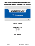
Computer interface software
Alarm Dial Tel Numbers
A call will be made to these numbers one after the other if any of the inputs are
triggered. Calls will be made after SMS is sent to SMS Alert Numbers.
Input Type
Select Input Type: Normally Open (NO), Normally Closed (NC) or Disable. All
unused inputs should be set as disabled.
When Input Activated
SMS Content*
Type the SMS message which will be sent to SMS alert numbers when
corresponding inputs are triggered. max 34 characters
When Input Recovered
SMS Content
Type the SMS message which will be sent to SMS alert numbers when
corresponding inputs are recovered. Tick "don't care" check box if you do not want
to use this feature. max 34 characters.( The unit will not make a call when the input
are recovered.)
Alarm Link Output Relay
When enabled, relay 1 will switch On when the inputs are triggered.
Sound Alarm
When enabled, the siren output will be activated for 60sec when any inputs are
triggered.
GSM Jammer
If there is no GSM signal present for 90 sec, relay 1 will switch on for 4minutes
and the siren output for 60sec. It's not recommended to enable this feature.
ARM
The GSM-4000 will automatically enter into armed mode on power up. If
unchecked it will not arm on power up
Report Time
This option will send SMS message to the 1st SMS alert number every set period
on the GSM-4000 status. Having 0 in this field will disable this feature.
Alarm Delay Time
Sets the delay time from input trigger to alarm switching.
Relay working time
Sets the off delay of relay 1 when any of the inputs are triggered.
Power Down Alert
Sets the time after which the unit will send SMS message when AC power
switches OFF
Password
Password to access the GSM-4000 when using SMS commands. Default is 1234.
Page 6
www.elsema.com
ELSEMA
GSM Receiver with relay output, GSM-4000
*In an event where the inputs are activated and held active, the GSM-4000 will only send one SMS message. It
will send another message if the same input is recovered and triggered again. This makes it ideal to be used for
monitoring temperature, moisture, humidity etc.
Computer Interface Setup
Please follow the following instructions carefully. Make sure that the "setup" switch is on setup and not "normal
operation" and the power switch is in Off position.
1.
Connect the GSM-4000 to your computer. Do not switch the GSM-4000 ON yet.
2. Install the USB driver provided from the Flash on your computer. (CP210xVCPInstaller.exe). The driver
can also be downloaded from Silicon labs website (CP210x).
3. The default COM selected should be COM3. If it does not work please see step 9.
4. Insert the SIM card into the SIM holder at the bottom side of the unit.
5. Now run the computer Interface software. It does not need installation.
6. Setup all the required parameters according to your application.
7. Click on the "Save Settings" button and after 2 secs switch on the GSM-4000. The On-Off switch is
beside the SIM card holder. If the setup is successful, a pop up window will open. If the setup is not
successful, you can try changing the COM ports. Correct COM port is indicated by the a green LED for
communications at the bottom of the COMPUTER interface window.
8. Switch Off the unit and then disconnect the USB cable.
Follow step 9 if COM port 1-5 don't work.
9. a. Go to the device manage in your controls panel of your computer.
b. Click on the Ports (COM &LPT)
c. You should see the USB driver here. Make note the COM port number. The COM port number should
be from 1-5. If it is not, go to properties and then change it. If you have to change the COM port setting,
you will need to restart you computer.
Application 1
Below is an example of a fully automatic tank/pump control system using two GSM-4000. The pump and the
tank can be any distance apart.
Page 7
www.elsema.com
ELSEMA
GSM Receiver with relay output, GSM-4000
Setting up the tank and the Pump unit.
1. Connect upper level switch to input 1 of the Tank unit.
2. Program the tank GSM unit so that when input 1 is activated, it sends SMS "1234DD" (1234 is the
default password. Please use your own password) to the SIM number on Pump GSM unit. This will
switch "Off" the pump
3. Connect the lower level switch to input 2 of the tank unit.
4. Program the tank GSM unit so that when input 2 is activated, it sends SMS "1234CC" (1234 is the
default password used as an example. Please use your own password) to the SIM number on Pump GSM
unit. This will switch "ON" the pump.
Notes:
Make sure that in the Tank unit, the first SMS alert number is that of the SIM card in the Pump GSM
Unit.
Application 2
Below is an example of a semi automatic Tank control unit. The GSM-4000 can be configured in 2 ways:
1. Switch On the pump for a certain period of time. The user should know how long it will take to fill the tank.
2. Switch pump On and Off with SMS messages after receiving the status of the tank.
In the 1st configuration the pump is connected to relay 1 of the GSM-4000. Input 1 is connected to the low level
switch on the tank. When the tank is empty, relay 1 is activated for a certain period of time thus switching the
pump On. The user can also have input 2 connected to a high level switch which will send the user an SMS
message when the tank is full.
In the 2nd configuration, the pump is connected to relay 2 of the GSM-4000. Input 1 is connected to the low
level switch on the tank. When the tank is empty, the user gets an SMS message. The user then sends a message
to switch On relay 2 which switches the pump. When the tank is full the high level switch connected to input 2
will send an SMS message to the user telling the tank is full. The user then sends another message to switch Off
relay 2 which switches the pump Off.
Page 8
www.elsema.com
ELSEMA
GSM Receiver with relay output, GSM-4000
Application 1 and 2 are just illustrations of how the GSM-4000 can be used. The GSM-4000 can be used in
many other ways depending on your imagination or your applications.
Optional
Optional microphone and Speakers can be connected to the GSM-4000 to create a 2-way communication under
the following 2 conditions:
1. When any of the inputs are triggered. The GSM-4000 makes a call to the user
2. When an authorised user makes a call to the GSM-4000.
When installing siren and microphone, please make sure that the siren is as far away as possible from the
microphone.
Manufactured by
Elsema Pty Ltd
31 Tarlington Place, Smithfield
NSW 2164
Ph: 02 9609 4668
Fax: 02 9725 2663
Website: http://www.elsema.com
Page 9
www.elsema.com