1
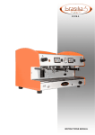
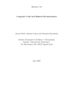
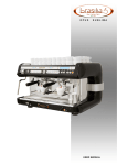
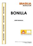
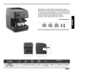
OPUS
USER MANUAL
Rev 0 - 09-2008
GENERAL INFORMATION
Manufacturer. ................................................
BRASILIA S.p.A.
Strada Provinciale Bressana - Salice
27050 Retorbido (PV) Italy
Tel. +39.0383.372011
Fax +39.0383.374450
e.mail: [email protected]
www.brasilia.it
Model.............................................................
Stamp of local agent ..................................... Rev. No.
0
Date
09/2008
Remarks
Document issued
OPUS
1. GENERAL INSTRUCTIONS
BRASILIA S.p.A. has taken every possible measure to ensure that the equipment operates safely and efficiently.
BRASILIA equipment comes with built-in safety devices to protect both users and authorised technicians.
• Read this manual carefully before installing the machine, starting it up and using it. Not doing so could cause
damage to the equipment, poor performance by the machine and health risks or personal injury.
• This manual should be treated as a part of the machine itself and should always be available to the user
and/or maintenance technician. If it gets lost, or you need further information, please get in touch with your
local retailer or with the manufacturer. The manual reflects the state of the art at this time and any updates
will not imply that it was inadequate. The manufacturer reserves the right to change the manual with no
obligation to update earlier editions, except in unusual circumstances. The Figures in this manual are purely
explanatory and might not look the same as all the models referred to in the instructions.
You must not:
• operate the machine without complying with the safety regulations in force in the country where it is
installed;
• operate the machine without an earth connection. Not complying with this instruction could lead to electric
shocks;
• replace or remove the safety stickers and the specifications plate affixed directly to the machine and its
packaging with a view to proper and safe installation and use;
• touch groups or nozzles while the machine is working. When handling the wands only touch them by the
grips. The beverages dispensed and some parts of the machine are hot and could cause burns or scalds;
• remove or tamper with any part of the machine; do NOT make arbitrary changes. Get in touch with the
authorised technician and specialist for your area;
• pull the line cord to unplug the electricity supply;
• allow children or unskilled staff to use the machine;
• expose the machine to the elements (sun, rain etc.);
• leave the machine in places where the ambient temperature is 0°C or lower because the water in the boiler
might freeze and cause damage;
• install the machine in places where jets of water that could reach the machine are used;
• operate the machine if any door or panel is not properly closed;
• stick spoons, forks or other utensils into the internal parts of the machine;
• operate the machine without water;
• to pour hot or boiling water into the machine;
• obstruct the air vents: you must leave a space of at least 10 cm between the machine and any walls and at
least 5 cm free on both sides, to allow proper ventilation.
For the machine to work properly you should use:
• only ground coffee, or, for models that have a special filter holder, cartridges.
• only cold tap water suitably softened (~7 French degrees).
• only original Brasilia S.p.A. spare parts
If these instructions are not followed, the guarantee does not apply and the manufacturer or the
maintenance technician declines all responsibility.
BRASILIA S.p.A. and the maintenance technician decline all responsibility in the following cases:
• if the machine is used in a manner other than as described in this manual;
• if the safety and maintenance instructions are not followed;
• if original BRASILIA spare parts are not used;
Rev 0 - 09-2008
ENGLISH / 1
• if the INSTALLER, or the MAINTENANCE TECHNICIAN, is not authorised and specialised;
• The INSTALLER or MAINTENANCE TECHNICIAN should inform the manufacturer about ANY
MALFUNCTIONS or improper uses that could adversely affect the original safety of the system.
• CHECK ON the condition of the parts and, if they are faulty, stop the installation and ask for them to be
replaced.
• If the machine is going to be left unused for a long time the electric power and water supply should
be disconnected.
1.1 - EXPLANATION OF SYMBOLS
Information given in this manual about hazard operations is marked with the following symbols, indicating:
Danger due to electricity
General danger or miscellaneous information
Heat danger (burns or scalds)
Danger because of damage to the machine.
1.2 - USE FORESEEN
The machine for making coffee with powder is designed and made solely for dispensing espresso coffee and
for preparing hot drinks (tea, cappuccino etc.) by using hot water or by emitting steam.
These are the only purposes for which the machine should be used and use for any other purpose is
considered improper and therefore dangerous.
1.3 - IMPROPER USE
The coffee machine is made and designed for food use only and the following are therefore forbidden:
- use of the machine by unqualified workers;
- adding liquids other than water;
- heating up drinks or other non-food substances;
- putting powders other than coffee into the filter holders;
- placing anything except cups on the cup warmer;
- placing containers with liquids on the cup warmer;
- obstructing the air grilles with cloths or other materials;
- covering the cup warmer with cloths;
- touching the dispensing areas with your hands;
- using the machine if it is very wet.
N.B.
In this paragraph we have listed some foreseeable situations of improper use; however the use of the
machine must comply with the instructions set out in the “Use foreseen” paragraph.
ENGLISH / 2
Rev 0 - 09-2008
CONTENTS
DECLARATION OF CONFORMITY...................................................................2
1 -
GENERAL WARNINGS. ................................................................................... 3
1.1 - Description of the symbols......................................................................... 4
1.2 - Intended use.............................................................................................. 4
1.3 - Incorrect use.............................................................................................. 4
2 -
TECHNICAL FEATURES.................................................................................. 7
2.1 - Dimensions................................................................................................ 7
2.2 - Description of the machine......................................................................... 8
2.3 - Identification of the components................................................................ 9
2.4 - Identification plate...................................................................................... 9
3 -
DESCRIPTION OF THE COMMANDS ........................................................... 10
3.1 - Version with display.................................................................................. 10
3.2 - P version.................................................................................................. 10
3.3 - Digit version............................................................................................. 10
4 -
USE ................................................................................................................. 11
4.1 - Starting up the machine........................................................................... 11
4.2 - Description of drink supply....................................................................... 11
4.3 - General rules for correct supply............................................................... 11
4.4 - Digit version coffee supply....................................................................... 12
4.5 - P version coffee supply............................................................................ 13
4.6 - Tea supply................................................................................................ 13
4.7 - Cappuccino preparation........................................................................... 14
4.8 - Steam and water supply........................................................................... 14
4.9 - Versions with Hyperwand......................................................................... 15
Rev 0 - 09-2008
ENGLISH / 3
CONTENTS
5- OPERATIONS TO PERFORM AT THE START OF THE DAY........................ 14
6- OPERATIONS TO PERFORM AT THE END OF THE DAY............................ 14
7 -
CLEANING ..................................................................................................... 15
5.1 - General cleaning rules............................................................................. 16
5.2 - Daily cleaning........................................................................................... 16
5.3 - Cappuccino maker cleaning..................................................................... 16
5.4 - Weekly cleaning....................................................................................... 16
8 - TROUBLESHOOTING . ............................................................................. 17-20
9 - DISPOSAL ...................................................................................................... 21
ENGLISH / 4
Rev 0 - 09-2008
2. TECHNICAL FEATURES
2.1 - Dimensions
FEATURE
NET WEIGHT (kg-lb)
2 GROUPS
76 Kg
3 GROUPS
93 kg
POWER
230V/50/1 - 3500W-15,2A F/N
220V/60/1 - 3500W-15,2A F/N
240V/50/1 - 3500W-15,2A F/N
400V/50/2 - 3500W-7,6 A F1/F2/N
400V/50/3 - 4500W-6,5 A F1/F2/F3
230V/50/1 - 5000W-21,7A
220V/60/1 - 5000W-21,7A
240V/50/1 - 5000W-21,7A
400V/50/2 - 5000W-10,8A F1/F2/N
400V/50/3 - 5500W-8 A F1/F2/F3
WATER FILLING CONNECTION
3/8” NOMINAL BORE
3/8” NOMINAL BORE
WATER DRAINING CONNECTION
Ø16-17mm
Ø16-17mm
OPERATING TEMPERATURE
+5° C +40 °
+5° C +40 °
STORAGE TEMPERATURE
+5° a +55°C
+5° a +55°C
RELATIVE HUMIDITY
5 ÷ 80%
5 ÷ 80%
SUPPLY PRESSURE
3bar max
3bar max
BOILER CAPACITY
11,4 L
18 L
RAISED VERSION
POWER
230V/50/1 - 3500W-15,2A F/N
220V/60/1 - 3500W-15,2A F/N
240V/50/1 - 3500W-15,2A F/N
400V/50/2 - 3500W-7,6 A F1/F2/N
400V/50/3 - 4500W-6,5 A F1/F2/F3
230V/50/1 - 5000W-21,7A
220V/60/1 - 5000W-21,7A
240V/50/1 - 5000W-21,7A
400V/50/2 - 5000W-10,8A F1/F2/N
400V/50/3 - 5500W-8 A F1/F2/F3
WATER FILLING CONNECTION
3/8”NOMINAL BORE
3/8”NOMINAL BORE
WATER DRAINING CONNECTION
Ø16-17mm
Ø16-17mm
OPERATING TEMPERATURE
+5° C +40 °
+5° C +40 °
STORAGE TEMPERATURE
+5° a +55°C
+5° a +55°C
RELATIVE HUMIDITY
5 ÷ 80%
5 ÷ 80%
SUPPLY PRESSURE
3bar max
3bar max
BOILER CAPACITY
11,4 L
18 L
Rev 0 - 09-2008
ENGLISH / 5
2.2 - DESCRIPTION OF THE MACHINE
The main features of the continuous supply coffee machine with electronic coffee dosage control are listed
below.
- Machine for ground coffee or coffee in pods or capsules (on request), with electronic microprocessor dosage
control using a push-button panel.
- Automatic boiler filling.
- Stainless steel body.
- Large capacity boiler: used to contain hot water and steam and made of nickel-plated copper in order to
ensure its properties remain unchanged over time.
- Supply group and heat exchanger: The brass supply group is the component in which, on attaching the
portafilter (containing the filter and the ground coffee or coffee pods), when the hot water arrives, the infusion
and supply phases for the drinks take place.
The heat exchanger, one for each group, is immersed in the boiler water and allows the mains water to be
brought up to the optimum temperature in a short time, preventing thermal imbalances to the system.
- Bullone Rosso (OPTIONAL) is the exclusive technology of Brasilia S.p.a. which, thanks to it particular
circuitry, allows the optimisation of heat stability, resulting in better coffee extraction.
- Heating element: made up of an electrical resistance immersed in the boiler water to allow water heating
and steam production.
- Rotary pump, with pressure control device.
Used to raise the mains pressure, normally insufficient for the purpose, to 9 bar, the ideal pressure to make
the best use of the coffee.
- Steam nozzles: steam production with a two-position lever allows steam to be used to prepare cappuccinos
or hot chocolates and heat water. Stainless steel nozzles.
- Hot water nozzle: a specific button allows the user to produce water to prepare hot drinks or infusions.
Stainless steel nozzles.
- Cappuccino maker (Optional): Emulsifies and heats the milk (using steam) to produce frothed milk for
making cappuccinos or hot milk.
- Control instruments:
Pressure gauges: these indicate the pressure in the boiler and the operating pressure of the pump.
Pressure switches: these check the pressure and insertion of the heat sources to keep the temperature of
the water in the boiler constant.
Level indicator: this marks the water level in the boiler.
Alarm lights: these show boiler filling and the insertion of the heating elements.
ENGLISH / 6
Rev 0 - 09-2008
2.3 IDENTIFICATION OF THE COMPONENTS
1
4
2
4
1
9
9
5
8
3
5
15
7
10
12
11
13
14
DETAIL N°
FUNCTION
1
2
3
STEAM TAP KNOB
PUSH BUTTON PANEL
• TO START UP STEAM SUPPLY
• TO SELECT DRINKS AND MACHINE PROGRAMMING
PRESSURE GAUGE
4
5
7
8
9
10
11
12
13
14
15
16
WATER TAP KNOB
STEAM NOZZLE
WATER LEVEL INDICATOR
GROUP WITH FILTER HOLDER
WATER NOZZLE
WATER FILLING TUBE
MANUAL FILLING BUTTON
DRAINAGE TUBE
MASTER SWITCH
WARNING LIGHT
ELECTRIC CABLE
VERSION WITH DISPLAY
• TO SHOW THE BOILER PRESSURE AND PUMP OPERATING
PRESSURE
• TO START UP WATER SUPPLY
• TO SUPPLY STEAM
• TO SHOW THE BOILER WATER LEVEL
• TO SUPPLY COFFEE
• TO SUPPLY WATER
• TO ALLOW WATER INTO THE MACHINE
• FOR MANUAL WATER FILLING
• TO DRAIN WATER FROM THE DRAINAGE TRAY
• TO SWITCH THE MACHINE ON AND OFF
• TO SHOW WHETHER THE RESISTANCES ARE ON
• TO CONNECT THE MACHINE TO THE ELECTRICAL MAINS
2.4 - IDENTIFICATION PLATE
The data shown on the identification plate is as follows:
A = Model
B = Serial n°
C = Year of manufacture
D = Power supply voltage
E = Frequency
F = Power
Rev 0 - 09-2008
ENGLISH / 7
3. DESCRIPTION OF THE COMMAND
3.1 DISPLAY VERSION (HYPERWAND)
Pulsantiera programmazione
ed utilizzo funzioni da display
Pulsante erogazione 1
dose acqua calda
LED segnalazione
lavaggio Hyperwand
Pulsante erogazione 2 dosi
acqua calda
Pulsante produzione
latte caldo
Pulsante produzione
latte schiumato
3.2 P VERSION
In the OPUS P version, there is only one supply button (fig.);
3.3 DIGIT VERSION
DESCRIPTION OF PUSH BUTTON PANEL
1 = CONT button LED (continuous supply)
2 = ESPRESSO COFFEE dose button LED
3 = DOUBLE ESPRESSO dose button LED
4 = STOP / Programming button LED 5 = ESPRESSO dose button LED
6 = DOUBLE ESPRESSO dose LED
ENGLISH / 8
- green LED
- green LED
- orange/green LED
- green LED
- green LED
Rev 0 - 09-2008
4. USE
4.1 - STARTING UP THE MACHINE
• Check that the water mains supply tap located upstream
from the machine is open.
• Check that the thermomagnetic differential switch located
upstream from the machine is in the “ON” position.
• Check that the water level in the boiler, shown by the indicator (1), is between the minimum level “MIN” and the
maximum level “MAX”.
• Turn the main switch (2) to the “ON” position for switch
on the machine (Fig.1).
• Turn the main switch (2) to the “
” position to activate heating of the water contained in the boiler (Fig. 2),
shown when light 1 comes on.
• Wait for the water temperature to reach the set value,
shown when the light goes off.
• Position the portafilters in the relative groups.
Check that the pressure in the boiler indicated by the
pressure gauge (7) is 0.9-1 bar.
• Switching on of the cup-heater surface (Optional):
In order to switch on the cup-heater resistance, press
button 1 (Fig. 3). When light 2 comes on, this shows that
the resistance is on.
Fig.1
Fig. 2
1
Fig. 3
2
4.1 DESCRIPTION OF DRINK SUPPLY
4.2 RULES FOR CORRECT SUPPLY
Always heat the cup by rinsing it with hot water: if the
cup is cold, the sudden change in temperature of the
espresso will change its taste.
- NEVER fill the portafilter without performing supply
immediately afterwards; the ground coffee “burns” in
the group and the resulting espresso will be very bitter.
- The machine operating process forces the water onto
the ground coffee at high pressure.
If the contact between the water and the ground coffee
lasts more than 20/30 seconds, the drink will taste unpleasant and bitter.
This effect is known as over extraction.
- Dose of ground coffee for ONE espresso coffee
between 6 and 7 g, for 2 coffees 12-14 g.
- Periodically, check for wear to the grinder part of the
grinder-doser.
Rev 0 - 09-2008
ENGLISH / 9
4.4. DIGIT VERSION COFFEE SUPPLY
1) Remove the portafilter from the group (A) and throw away the
grounds by knocking the edge of the portafilter on the bar of the
coffee ground drawer.
It is advisable not to knock the portafilter against an unprotected
surface; the portafilter seal could be damaged.
The small quantity of ground coffee which is left will not have a
negative effect on the taste of the coffee supplied.
2) Fill the portafilter with finely ground coffee, positioning the
portafilter in its position on the base of the grinder-doser (B) and
pulling the lever (C) once for a single coffee and twice for a double
dose.
Caution: always remember to pull the grinder-doser lever as far as
it will go; then let it return to the rest position by itself.
Ensure that the grinder-doser has enough ground coffee in its container for at least one dose.
3) Once the portafilter for espresso coffee supply is full, press the
ground coffee using the tamper.
Clean the edge of the portafilter to remove any excess ground coffee, in order to ensure that there is a perfect seal between the portafilter and the machine.
If the user has a mixed use filter, it is possible to insert a pod of
coffee instead of the ground coffee.
4) Attach the portafilter to the group, turning it until it is secure
(D).
Do not tighten too much, in order to prevent the portafilter from
being difficult to remove after supply.
5) After having attached the portafilter correctly, place a previously
heated cup (~40°C), under the spout.
In the case of a double portafilter, use two cups.
6) Press the push button panel key (*), which corresponds to the
drink to be supplied.
(*) CONTINUOUS SUPPLY:
In order to have continuous supply (non-dosed), proceed as described in points 1)-5) and press the CONT button (1).
Once the required quantity of coffee in the cup has been reached,
press the STOP button (4).
Caution: if continuous supply is not stopped manually using the
STOP button within the time limit of 120 seconds, the group is
blocked and the orange block LED (4) comes on.
In order to restart the machine, disconnect power for at least 5
seconds and then reconnect it.
ENGLISH / 10
Rev 0 - 09-2008
4.5 P VERSION COFFEE SUPPLY
Proceed as described in points 1) - 5) in the “DIGIT version supply” paragraph.
In order to start supply, press the switch located above the chosen
group.
When supply has reached the required quantity, press the button
again to interrupt it.
4.6 TEA SUPPLY
(for OPUS TEA versions)
CAUTION! Use only ground tea leaves (Dose ± 3 grams per
150 cc.)
• Remove the portafilter from the group (A) and throw away the
grounds by knocking the edge of the portafilter on the bar of the
ground drawer.
It is advisable not to knock the portafilter against an unprotected
surface; the portafilter seal could be damaged.
The small quantity of ground coffee which is left will not have a
negative effect on the taste of the coffee supplied.
• Fill the portafilter with finely ground tea.
• Once the portafilter is full, press the tea using the tamper.
Clean the edge of the portafilter to remove any excess ground
coffee, in order to ensure that there is a perfect seal between the
portafilter and the machine.
• Attach the portafilter to the group, turning it until it is secure
(D).
Do not tighten too much, in order to prevent the portafilter from
being difficult to remove after supply.
• After having attached the portafilter correctly, place a previously
heated cup (~40°C), under the spout.
In the case of a double portafilter, use two cups.
• Press the push button panel key which corresponds to the drink
to be supplied.
CONTINUOUS SUPPLY:
Prepare the group with the require dose of ground tea as normal,
attach the portafilter to the group (D) and press the CONT button
(1).
Once the required quantity of tea in the cup has been reached,
press the STOP button (4).
Caution: if continuous supply is not stopped manually using the
STOP button within the time limit of 120 seconds, the group is
blocked and the orange block LED (4) comes on.
In order to restart the machine, disconnect power for at least 5
seconds and then reconnect it.
Rev 0 - 09-2008
ENGLISH / 11
4.7. HOW TO MAKE CAPPUCCINO
In order to prepare a cappuccino in a professional way, it is necessary to
“froth” the fresh milk (±4°C) until obtaining the foam which will be poured onto a freshly supplied espresso coffee.
1 - Activate the steam for 1 or 2 seconds in order to clean the nozzle of
milk residues.
2 - To heat the milk, use a metal or ceramic milk jug, at least half filled
with fresh milk.
3 - Bring the milk jug up close to the steam nozzle in order to immerse the
spout in the milk for ~1-2cm.
Keep the milk jug tilted and the nozzle not in the centre and not in contact
with the edge.
4 - Open the steam tap slowly and move the milk jug in a circular direction in until the milk begins to froth
5 - Close the steam tap quickly.
6 - Extract the nozzle from the frothed milk, tap the milk jug in order to
stabilise the bubbles and, moving the milk jug backwards and forwards,
pour the foam onto the espresso.
MODEL WITH CAPPUCCINO MAKER (OPTIONAL):
(Fig. 1)
Insert the milk inlet tube (B) into a container with fresh milk (± 4°C),
place a cup with 1 dose of espresso coffee under the cappuccino maker
spout: press the cappuccino maker switch. When the quantity of frothed
milk in the cup is sufficient, press the switch again to halt supply and
serve the cappuccino.
Fig.4
Fig. 1
A
B
4.8 HOT WATER AND STEAM SUPPLY
• Turn on the hot water/steam tap to start supply.
• Turn off the tap to interrupt supply.
C
Caution: The nozzles are very hot. Do not touch them until they have cooled down.
Only move the nozzles using the specific protection devices.
Clean the nozzles immediately after use, in order to prevention the formation of deposits which can be difficult to remove. Inform the customer as soon as possible that the drink is very hot.
Keep the frothed milk aside for the next cappuccino.
NEVER heat the same milk. Always add COLD milk to what is left in the milk jug.
NOTE: The temperature of the steam is regulated on the basis of a certain quantity of milk in the jug.
So as not to encounter any variations in temperature during normal machine use, it is advisable to always use the same quantity.
ENGLISH / 12
Rev 0 - 09-2008
4.9 HOT WATER AND STEAM SUPPLY VERSIONS WITH HYPERWAND
Fig. A
HOW TO USE THE HYPERWAND
• Insert the hyperwand nozzle (fig.a - 1) fully into the milk contained in
the jug,
CAUTION: the temperature of the milk must be approximately 4°C).
3
2
• Choose whether to have hot milk or frothed milk by selecting one of the
two buttons located on the control panel (fig.a - 2).
Steam supply comes to a halt automatically on reaching the preset temperature.
Note: Supply can be interrupted at any moment using the previously selected button.
1
DOSED HOT WATER SUPPLY
• Press one of the two buttons (fig.a - 3) on the control panel, corresponding to the dose of water required: supply will begin and end automatically.
AUTOMATIC CLEANING:
after using the Hyperwand, if the device is out of use for a period of time
programmed beforehand, the automatic cleaning cycle begins.
LED “1” starts to flash and the display shows the “Push Steam Button”
alarm.
Press one of the two drink selection buttons: “Hot Milk” or “Frothed
Milk” (fig.a - 2).
Once this operation has been performed, cleaning begins and lasts 15 to
25 seconds.
The cleaning cycle can be programmed within a time period from 1 minute to a maximum of 5 minutes from the last steam supply.
Fig. A
1
2
CAUTION: DANGER OF BURNS!
Rev 0 - 09-2008
ENGLISH / 13
5- OPERATIONS TO PERFORM AT THE START OF THE DAY
1 - CHECK BOILER PRESSURE: The pressure of the boiler must be between 0.9 and 1.1 BAR.
Switch on the machine, then check the existing pressure on the pressure gauge; if it is different from
the pressure shown, it is necessary to have the pressure switch inside the machine serviced by a
technician.
2. Discharge all steam from the boiler using the steam delivery taps to check that the pressure
switch and vacuum valve operate correctly.
3. Check that the water level in the boiler is approximately 70%.
4. Perform water delivery from the unit spouts without filter holders attached in order to check that
the water falls correctly without coming out in separate or pressurised sprays, indicators of many
blocked holes.
5. Check that the delivery pressure is 9 BAR.
6- OPERATIONS TO PERFORM AT THE END OF THE DAY
1. Detach and empty the filter holders, then remove the filters and wash them carefully.
2. Carry out cleaning operations as described in the relative chapter.
3. In the case of the OPUS gas version, once the working day is over, it is advisable to switch it off
for safety reasons.
For the electric version, it is advisable to leave it switched on in order to prevent any delays in heating up at the start of the day, and to prevent the salts present in the boiler from forming deposits.
4. It is also advisable to empty the boiler periodically in order to prevent the stagnation of the water
present inside and the formation of deposits.
ENGLISH / 14
Rev 0 - 09-2008
7 CLEANING
7.1 GENERAL CLEANING RULES
- Do NOT use jets of water to clean the machine.
- Do NOT use detergents containing alcohol or ammonia or use abrasive sponges to clean the machine.
- USE specific detergents for cleaning coffee machines or dishes only.
- The chemical detergents used for cleaning the machine and/or the system must be used with care so as not to deteriorate
the components and the environment (degradability greater than 90%).
- Constant grinder-doser cleaning and checking of wear to the grinder.
- Carefully clean the steam and Hyperwand nozzles used to heat drinks immediately after use, in order to prevent the formation of breeding grounds for bacteria or deposits which could obstruct the holes in the diffuser and to prevent different
types of previously heated drink from altering the taste of the drinks being heated.
CAUTION: Incorrect maintenance and cleaning, with the use of non-softened water, or damage to the internal parts may
lead to unexpected interruptions to the flow of water and unexpected jets of liquid or steam, with serious consequences!
7.2 DAILY CLEANING OPERATIONS
Clean the sprayhead, saucer gaskets and portafilter guides of the supply groups with a cloth/sponge.
Rinse the filters and portafilters in hot water adding specific detergent, in order to remove greasy coffee deposits.
Attach and detach the portafilter to the group, after having mounted the blind filter, performing a few supplies.
Automatic group cleaning:
• Prepare the group as follows:
1) Detach the portafilter from the group (detail A fig.1) and replace the supply filter (detail B fig.1) with the blind filter
(detail C fig.1).
2) Place the recommended quantity of detergent into the blind filter (detail D fig.1).
3) Reattach the portafilter to the group (detail E fig.2).
4) Access to the cleaning phase takes place by pressing the STOP button four times in a row on each push button panel.
5) At this point, the machine will start up the coffee group washing phase which will last 3 minutes in total.
The washing phase is divided as follows: 30 seconds of operation, 5 seconds of pause, all repeated 5 times. The whole
duration of the washing phase is shown by the flashing of the green dose LEDs and the orange LED (details 2-3-4-5-6 see push button panel diagram).
Fig. A
Fig. B
6) The cycle can be interrupted by pressing STOP on the respective push button panels.
7) The end of every washing cycle is shown when one of the green dose LEDs (details 2-3-5-6) goes off. When all the
LEDs are off, the cycle has come to an end.
Rev 0 - 09-2008
ENGLISH / 15
• The group rinsing phase is similar to the washing procedure.
8) Detach the portafilters (detail F fig.2) and replace the blind filters (detail G fig.3) with the supply filters
(detail H fig.3).
9) Reattach the portafilters (detail E fig.2).
10) Press the CONT button (detail 1); press the STOP buttons on the respective push button panels.
Fig.1
Fig.2
Fig.3
7.3 CLEANING THE CAPPUCCINO MAKER (OPTIONAL):
CAUTION! HOT LIQUID!
It is advisable to perform the following operations at the end of every working day:
1 - Immerse the milk inlet tube (B - Fig.4) in a glass of water, press the “Cappuccino”
button and supply water for a few seconds. For more thorough cleaning:
2 - Remove the cappuccino maker from the support and disassemble it completely.
3 - Place everything in a container and cover it with a detergent solution suitable for
cleaning dishes (remove any solid milk deposits beforehand).
4 - Wash and rinse thoroughly with running water, the put the cappuccino maker back
together and place it back in its position.
Fig.4
A
B
C
A = Steam tube
B = Milk inlet tube
C = Air inlet tube
7.4 WEEKLY CLEANING OPERATIONS
Clean the basin and cup-holder grille:
Remove the cup-holder grille, pull out the drainage basin and clean it. Also check the plastic drainage tray, cleaning it if necessary, removing the remains of the coffee grounds with the aid of a spoon.
Cleaning the body:
Use a damp, non-abrasive cloth on all the surfaces.
Do not use products containing alcohol or ammonia which could damage the machine components.
ENGLISH / 16
Rev 0 - 09-2008
8. TROUBLESHOOTING
• The user (the installer or maintenance technician) is obliged to notify the manufacturer of any faults or deterioration which could jeopardise the original safety of the system.
• Each fault must be notified immediately to the authorised, qualified technician. Only an authorised technician
can install, repair or perform maintenance operations on the machine. The non-observance of this instruction
can render the warranty void and cause serious damage.
• If an alarm blocks the machine, ensure that it is not just a temporary system error, resetting the functions of
the machine by switching it off and back on again.
• If the power cable is damaged, it must be replaced with one which has the same characteristics, exclusively
by an authorised, specialised installer/maintenance technician. The non-observance of this instruction may
cause damage to the machine and lead to electric shocks.
Rev 0 - 09-2008
ENGLISH / 17
MALFUNCTION
CAUSES
TROUBLESHOOTING
** = Maintenance and repair operations can only be performed by authorised, specialised personnel. For the user: contact customer service!
Orange LED “4” on (see push button • Group block: in continuous supply, In order to restart the machine, disconpanel diagram).
the supply is not stopped manually nect power for at least 5 seconds and
using the STOP button within the time then reconnect it.
limit of 120 seconds.
• Malfunctioning of the volumetric
doser: the anomaly is shown by the
flashing of the LED on the push button panel of the group affected by the
anomaly. In this case, the supply is not
dosed but if the operator does not intervene manually with the STOP button, blocking takes place on reaching
the time limit.
• In order to prevent water leakage,
the auto-level is equipped with a safety
device. If the auto-level solenoid valve
remains open for more than 90”, it is
automatically deactivated and the anomaly is shown by the flashing of LED
“4” on all the push button panels.
No water comes out of the group and • The mains tap or purifier taps are tur- • Open the taps.
the pump is noisy.
ned off.
• The water inlet connector filter is blo- • Remove and clean.
cked.
No water comes out of the group.
• The gicleur is blocked.
• The injector is blocked
• (only for versions with volumetric
dosage) The doser inlet connector is
blocked.
• The solenoid valve does not open:
• No power reaches the coil.
• The coil is interrupted.
• The core is blocked.
•** Remove the gicleur cap, check, clean or replace if necessary.
•“ Remove and clean, replace if necessary.
Note: check purifier resin regeneration.
•** Remove and clean.
• “ Check the solenoid valve:
• Check and reset the electrical connections.
• Replace
• It is advisable to replace the whole
solenoid valve.
The boiler is pressurised but the group • Air has not been removed from the
does not heat up.
boiler during the boiler water heating
phase.
• The thermosiphon circuit is partially
blocked.
• ** When cold, check that the air vacuum valve is not blocked shut. Replace if necessary.
• ** Check the group supply and return tubes and connectors. Clean and
replace if necessary.
Note: check purifier resin regeneration.
The boiler does not heat up.
ENGLISH / 18
• The resistance is interrupted.
• ”Replace.
• No power reaches the resistance:
• ** Check and replace the malfunctiothe safety thermostat, the pressure ning components if necessary.
switch and/or the master switch are
faulty.
Rev 0 - 09-2008
MALFUNCTION
CAUSES
TROUBLESHOOTING
** = Maintenance and repair operations can only be performed by authorised, specialised personnel. For the user: contact customer service!
The auto-level takes in water when it • The electrical connection between the
should not and the level warning light is level probe and the control unit has been
on.
interrupted.
• The electrical connection between the
frame mass and the control unit has been
interrupted.
• The level probe is dirty.
• The electronic control unit is faulty.
• ** Check and restore connection.
• ** Check and restore connection.
• ** Clean; when disassembling, do not
take it off the isolator but remove it completely from the connector.
• ** Replace.
The auto-level does not take in water when • The probe is touching glass or earthed • ** Check and reposition.
it should and the warning light is off.
metal parts.
• ** Check and replace if necessary
• The electronic control unit is faulty.
The auto-level does not take in water when • The filling solenoid valve coil has been • ** Check and replace if necessary.
it should and the warning light is on.
interrupted.
• ** Check and replace if necessary.
• The core of the filling solenoid valve has
been interrupted.
The level of water in the boiler continues • Level probe not connected
to rise until leaking out of the safety val- • There is a foreign body inside the autove.
level solenoid valve.
• There is a foreign body inside the seal
site.
• The gasket is worn.
• ** Check and replace if necessary.
• ** Check and replace if necessary.
• ** Check.
• ** Check and replace if necessary.
The graduated visual level does not indica- The lower tube which connects the level to ** Disassemble and clean.
te the real level of water in the boiler.
the boiler is blocked.
The boiler is pressurised but the group • The control unit fuses have blown.
does not supply.
• The supply switch is faulty
• The solenoid valve does not open.
** Check and replace if necessary.
The machine only supplies when the re- The “neutral” is missing in the electrical ** Check and re-establish.
sistance is powered electrically (red light power supply.
on).
Supply does not occur in regular doses.
Rev 0 - 09-2008
• There is a leak in the volumetric doser.
• The doser rotor does not rotate freely.
• The supply solenoid valve leaks from the
drain.
• The expansion valves leak during supply.
• ** In the presence of humidity outside
the doser and in the diode-holder flange,
replace the doser.
• ** Replace the doser.
• ** Check and replace if necessary.
• ** Check the calibration and if necessary
the gasket.
Caution:
Do not unscrew the regulation connector
of the expansion valve fully while the boiler is pressurised.
• ** Check and replace if necessary.
ENGLISH / 19
MALFUNCTION
CAUSES
TROUBLESHOOTING
** = Maintenance and repair operations can only be performed by authorised, specialised personnel. For the user: contact customer service!
Insufficient use made of the coffee
• Incorrect pump pressure.
•Incorrect expansion valve calibration.
• Incorrect supply temperature.
• The thermosiphon circuit is partially
blocked.
• The granulometry of the ground coffee is incorrect (too fine or too large).
• The sprayhead and filters are partially blocked.
• ** Regulate the pressure, checking
the pressure gauge during supply. Calibration value: 9 bar.
•** Regulate calibration.
•** Check the temperature using the
thermometer during supply at the portafilter spout outlet.
Intervene if necessary, using the pressure switch.
•** Check the circulation reducer and
replace if necessary.
• Check the supply time and adjust
grinding if necessary.
•** Check and replace if necessary.
Leaks from the water and steam noz- Faulty seal or foreign body present in ** Check and replace if necessary.
zles occur while the relative taps are the seal site.
turned off.
Leaks of water or steam occur under Faulty tap axis gaskets.
the tap knobs when turning on.
** Check and replace if necessary.
A leak occurs between the group and Faulty saucer gasket or irregular filter ** Replace.
portafilter during supply.
edge.
Water leakage from the block ring nut. Faulty gasket
** Replace.
Water leakage from the block ring nut Faulty tap gasket.
during manual filling.
** Replace.
Only for versions with display and HyperWand:
“PUSH STEAM BUTTON” The alarm appears at the See “CLEANING” chapter.
alarm
end of the programmed
time from the last use of the
Hyperwand.
ENGLISH / 20
Rev 0 - 09-2008
9. DISMANTLING
• Taking the machine out of use must be done by authorised staff. The pressure of the water circuit must be
fully lowered, the power cord disconnected and any substances potentially harmful to the environment must
be disposed of legally and properly.
• Keep the machine out of the reach of children or unqualified persons.
• If the machine is to be disposed as waste, it must be taken to a centre authorised for recycling
electrical and electronic equipment (*). This is to protect the environment and humans from any
possible harm. For more information about recycling please contact the offices of the municipality
concerned, the domestic waste disposal service or the retailer.
• Do not dispose of the material in the environment.
(*)
As per art. 13 Legislative Decree 25 July, no.151 “Implementation of the Directives2002/95/
EC,2002/96/EC and 2003/108/EC, on the restriction of the use of certain hazardous substances
in electrical and electronic equipment and on waste electrical and electronic equipment”
The crossed out garbage-bin symbol found on the equipment or on its package specifies that the product, at
the end of its working life, must be separated from other waste.
The proper differentiated collection for subsequent recycling of the equipment, its treatment and environmentally
compatible disposal helps prevent potential negative effects on the environment and on health and promotes
re-usage and/or recycling of the materials forming part of the equipment.
Illicit disposal of the product by the possessor is subject to administrative fines as laid down in the regulations
in force.
Rev 0 - 09-2008
ENGLISH / 21
BRASILIA S.p.A.
Strada provinciale Bresana-Salice T.
27050 RETORBIDO (Pavia) ITALY
Tel. +39.0383.372011 - Fax. +39.0383.374450
www.brasilia.it - E-mail: [email protected]
ENGLISH / 22