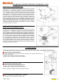
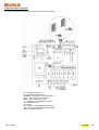
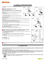
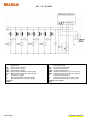
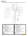
1
MANUALE DI ISTRUZIONI
TECHNICAL MANUAL
PROFESSIONAL
PROFESSIONAL
PROFESSIONAL
PROFESSIONAL
OPUS
ATTENZIONE: LEGGERE LE ISTRUZIONI
CAREFULLY READ THE INSTRUCTIONS
BRASILIA S.p.A. - STRADA PROVINCIALE BRESSANA-SALICE - 27050 RETORBIDO (PV) ITALY
Tel.+39.0383.372011 - Fax +39.0383.374450 - www.brasilia.it - [email protected]
DATI GENERALI - GENERAL DATA
COSTRUTTORE - MANUFACTURER:
BRASILIA S.p.A. Strada Provinciale Bressana - Salice
27050 Retorbido (PV) Italia
Tel.: + 39.383.372011 - Fax: + 39.383.374450
www.brasilia.it - [email protected]
MODELLO - MODEL:
OPUS
VERSIONI - VERSIONS:
Digital - P
TIMBRO RAPPRESENTANTE LOCALE - SERVICE COMPANY STAMP:
Rev. N.
Data
0
11/2005
EMISSIONE DOCUMENTO
1
11/2006
HYPERWAND
2
04/2007
AGGIORNATI SCHEMI - REVISIONE HYPERWAND
REV. 2 04/2007
Note
ITALIANO - 1
INDICE
1. SICUREZZA E AVVERTENZE .....................................................................................................................................................................................3
2. INTRODUZIONE ...........................................................................................................................................................................................................4
SEZIONE “A” – Installazione e Manutenzione ...................................................................................................................5
3. INSTALLAZIONE E COLLEGAMENTI.........................................................................................................................................................................6
3.A. COME RIMUOVERE LA MACCHINA DALL’IMBALLO......................................................................................................................................6
3.B. DATI GENERALI COLLEGAMENTI ....................................................................................................................................................................6
3.C. COLLEGAMENTO IDRAULICO ..........................................................................................................................................................................7
3.D. COLLEGAMENTO ELETTRICO ..........................................................................................................................................................................7
3.D.1. COLLEGAMENTO EQUIPOTENZIALE: .....................................................................................................................................................8
4. PROCEDURE DI FUNZIONAMENTO ..........................................................................................................................................................................8
4.A. MESSA IN FUNZIONE .........................................................................................................................................................................................8
4.B. MESSA IN FUNZIONE VERSIONE CON IMPIANTO A GAS .............................................................................................................................9
4.C. REGOLAZIONI .....................................................................................................................................................................................................9
5. PROGRAMMAZIONE DOSI VERSIONE DIGIT .........................................................................................................................................................10
5.A. MODELLI 1 GRUPPO ........................................................................................................................................................................................10
5.B. MODELLI 2-3-4 GRUPPI ...................................................................................................................................................................................10
5.C. SEGNALAZIONE ANOMALIE ...........................................................................................................................................................................11
5.D. LAVAGGIO AUTOMATICO GRUPPI CAFFÈ ...................................................................................................................................................11
5.E. CONTROLLO MACINATURA SULLA MACCHINA ..........................................................................................................................................11
6. VERSIONI CON DISPLAY E HYPERWAND (Optional) .....................................................................................................................................13
6.A. PROGRAMMAZIONE ..........................................................................................................................................................................................13
6.A.1. AUTOTEST ALL'ACCENSIONE: ...........................................................................................................................................................14
6.A.2. PROGRAMMAZIONE OROLOGIO: ...........................................................................................................................................................14
6.A.3. ACCENSIONE / SPEGNIMENTO: .........................................................................................................................................................14
6.A.4. "CLEANING ALARM" - RIGENERAZIONE FILTRI ADDOLCITORE ACQUA: ..................................................................................14
6.A.5. PREINFUSIONE: ...................................................................................................................................................................................14
6.A.6. CONTROLLO MACINATURA (Solo per gruppi caffè espresso):...........................................................................................15
6.A.7. TEMPO DI LAVAGGIO...........................................................................................................................................................................15
6.A.8. RITARDO LAVAGGIO LATTE:..............................................................................................................................................................15
6.A.9. TEMPERATURA LATTE: ........................................................................................................................................................................15
6.A.10. TASTO EROGAZIONE CONTINUA: .....................................................................................................................................................15
6.A.11. PASSWORD............................................................................................................................................................................................15
6.A.12. VISUALIZZAZIONE TEMPERATURA / PRESSIONE:.......................................................................................................................16
7. MALFUNZIONAMENTI E SOLUZIONI .......................................................................................................................................................................16
8. MANUTENZIONE........................................................................................................................................................................................................18
8.A. ISTRUZIONI PER SCARICARE L'ACQUA DELLA CALDAIA .........................................................................................................................18
8.B. ISTRUZIONI PER LA RIGENERAZIONE DEL DEPURATORE........................................................................................................................18
SEZIONE “B” – Istruzioni per l’Utilizzatore ......................................................................................................................19
9. DESCRIZIONE COMPONENTI...................................................................................................................................................................................20
10. DESCRIZIONE EROGAZIONE BEVANDE ..............................................................................................................................................................21
10.A. EROGAZIONE CAFFÈ VERSIONE DIGIT ......................................................................................................................................................21
10.B. EROGAZIONE CAFFÈ VERSIONE P..............................................................................................................................................................21
10.C. COME FARE IL CAPPUCCINO .......................................................................................................................................................................21
10.D. EROGAZIONE ACQUA CALDA E VAPORE ..................................................................................................................................................22
10.E. EROGAZIONE ACQUA CALDA E VAPORE - VERSIONI CON HYPERWAND .............................................................................................22
11. PULIZIA.....................................................................................................................................................................................................................22
11.A. PREVENZIONE SANITARIA ...........................................................................................................................................................................23
11.B. OPERAZIONI DI PULIZIA GIORNALIERA......................................................................................................................................................23
11.C. OPERAZIONI DI PULIZIA SETTIMANALI.......................................................................................................................................................24
12. SMANTELLAMENTO ...............................................................................................................................................................................................24
SEZIONE “C” - Dati tecnici, Schemi elettrici ed idraulici……………………………………………………………….……. 1
REV. 2 04/2007
ITALIANO - 2
1. SICUREZZA E AVVERTENZE
BRASILIA S.p.A. ha preso ogni possibile precauzione per un funzionamento sicuro e un’attrezzatura efficiente. I dispositivi di sicurezza incorporati, che fanno parte della dotazione BRASILIA, mirano a proteggere gli operatori ed i tecnici autorizzati.
• NON far funzionare la macchina senza aver prima letto le informazioni contenute nel presente manuale. L’inosservanza di questa istruzione può causare danni all’attrezzatura, scarse prestazioni della macchina, rischi per la salute o danni personali.
Il presente manuale è da considerarsi parte integrante della macchina e deve essere sempre a disposizione dell’utilizzatore e/o manutentore. In caso di smarrimento o di richiesta di ulteriori informazioni, contattare il rivenditore di zona o il costruttore. Il manuale rispecchia lo stato della tecnica al momento attuale e non può essere considerato inadeguato per eventuali successivi aggiornamenti: il costruttore si riserva il diritto di modificare il manuale senza l’obbligo di aggiornare le edizioni precedenti, salvo casi eccezionali.
Le immagini, riportate nel presente manuale, sono esclusivamente esplicative e potrebbero non rispecchiare l’estetica di tutti i modelli a
cui si riferiscono le istruzioni.
• NON far funzionare la macchina senza rispettare le regole di sicurezza in vigore nel paese d’installazione, così come le regole dettate
dal comune buonsenso. Accertarsi che le operazioni di manutenzione vengano effettuate regolarmente e correttamente.
• NON far funzionare la macchina in assenza di collegamento di messa a terra. L’inosservanza di questa istruzione può dare luogo a
scosse elettriche.
• NON sostituire o rimuovere le istruzioni di sicurezza ed i dati tecnici affissi direttamente sulla macchina e sull’imballo, per
un’installazione ed un utilizzo corretti e sicuri.
• NON toccare gruppi o beccucci durante il funzionamento della macchina. Le lance devono essere maneggiate soltanto tramite apposite impugnature. Le bevande erogate e alcune parti della macchina sono calde e possono causare ustioni.
• NON toccare tasti o interruttori durante il ciclo di erogazione.
• NON rimuovere o manomettere alcun elemento della macchina e NON effettuare modifiche arbitrarie. Contattare il tecnico autorizzato
e specializzato di zona.
• NON tirare il cavo di alimentazione elettrica per disinserire la spina.
• NON lasciare che la macchina venga usata da bambini o personale inadatto.
• NON esporre la macchina agli agenti atmosferici (sole, pioggia ecc...).
• NON far funzionare la macchina se ogni sportello o pannello non è chiuso correttamente.
• NON inserire cucchiai, forchette o altri utensili nelle parti interne della macchina durante il suo funzionamento.
• NON far funzionare la macchina in assenza d’acqua.
• NON ostruire le prese d’aria o le aperture di scappamento: lasciare almeno 10 cm. di spazio tra la macchina ed eventuali pareti ed
almeno 5 cm su entrambi i lati, per permettere una corretta ventilazione.
• USARE solo caffè macinato o cialde di caffè per modelli con portafiltro dedicato.
• USARE solo acqua fresca di rete opportunamente addolcita (~7 gradi francesi).
• USARE solo ricambi originali Brasilia S.p.A.: non rispettare quest’indicazione esclude le possibilità di beneficio della garanzia e declina il costruttore o il tecnico manutentore da ogni responsabilità.
• EFFETTUARE le operazioni di pulizia quotidiane e settimanali raccomandate.
PULIZIA:
- NON usare getti d’acqua per la pulizia della macchina.
- NON usare detergenti contenenti alcool, ammoniaca o spugne abrasive per la pulizia della macchina.
- USARE solo detergenti specifici per la pulizia di macchine per caffè o stoviglie.
- I detergenti chimici utilizzati per la pulizia della macchina e/o dell’impianto vanno usati con cura per non deteriorare i componenti e
l’ambiente (degradabilità superiore al 90%).
- Pulizia costante del macinadosatore e controllo dell’usura delle macine.
ATTENZIONE: Una manutenzione e una pulizia improprie, con l’uso di acqua non addolcita, o danni alle parti interne possono causare
eventuali interruzioni improvvise del flusso d’acqua ed inattesi getti di liquido o di vapore, con conseguenze gravi. Prestare attenzione
durante la pulizia e l’utilizzo della macchina!
PREVENZIONE SANITARIA:
Il caffè, ed i suoi eventuali ingredienti (latte, zucchero, ecc.), sono prodotti sensibili, per questo motivo devono essere prese in considerazione le seguenti operazioni per l'igiene di base. I punti che seguono possono incidere sulla qualità del prodotto finito:
• Lavare bene le mani, fino ai gomiti. Lavarle periodicamente anche durante l’arco della giornata.
• Indossare guanti di gomma in presenza di tagli o abrasioni sulla pelle.
• Pulire completamente tutte le parti e i componenti della macchina.
• Utilizzare i detergenti consigliati.
• Conservare i prodotti detergenti in un luogo fresco e asciutto. Utilizzare secondo le istruzioni riportate sulle confezioni.
• Lasciare all'utilizzatore il tempo necessario per completare le procedure di pulizia.
• Non trascurare le operazioni di pulizia quotidiane: procedere come da sezione “PULIZIA” nel manuale per l’utilizzatore.
• Disporre le scorte in modo che vengano utilizzate prima quelle con scadenza a breve termine. Controllare sempre la data di scadenza. I prodotti non devono essere conservati all’aperto o esposti direttamente alla luce solare.
AVVERTENZE PER INSTALLATORE E MANUTENTORE:
• BRASILIA S.p.A. ed il tecnico manutentore declinano ogni responsabilità nei seguenti casi:
se la macchina viene usata in modi differenti rispetto a quelli descritti nel presente manuale
se non vengono rispettate le prescrizioni di sicurezza e di manutenzione
se non vengono utilizzati parti di ricambio originali BRASILIA.
se L’INSTALLATORE, o il TECNICO MANUTENTORE, non è autorizzato e specializzato.
se, a causa delle differenti condizioni di trasporto e/o installazione, si presentano situazioni incontrollabili o imprevedibili, nonostante L’INSTALLATORE abbia preso ogni possibile precauzione per garantire la sicurezza dell’utente. Prestare sempre la massima
attenzione!
• L’INSTALLATORE o il TECNICO MANUTENTORE devono informare il costruttore di POSSIBILI MALFUNZIONAMENTI o usi impropri che potrebbero intaccare la sicurezza originale del sistema.
• L'apparecchio deve essere installato dove l'uso e la manutenzione sono riservate a personale qualificato.
• CONTROLLARE le condizioni dei componenti e, se difettosi, fermare l’installazione e chiedere la loro sostituzione.
REV. 2 04/2007
ITALIANO - 3
• LE OPERAZIONI DI MANUTENZIONE devono essere effettuate regolarmente. La temperatura ambientale in cui svolgere le operazioni di manutenzione deve essere di minimo 5°C e massimo 30°C (gradi centigradi).
• VERIFICARE che il piano, su cui verrà posizionata la macchina, non sia inclinato.
• Posizionare la macchina su un ripiano abbastanza alto da permettere che lo scaldatazze sia situato ad almeno 150 cm. di altezza dal pavimento
• RUMORE AEREO: nel luogo di lavoro della macchina non viene normalmente superato il livello di pressione sonora di 70
dB.
• La macchina non deve essere installata dove viene usato un getto d'acqua.
• Se la macchina dovesse rimanere inutilizzata a lungo, scollegare il cavo dal quadro elettrico e chiudere il rubinetto di alimentazione idrica.
AVVERTENZE D’USO:
- Riscaldare sempre la tazza risciacquandola con acqua calda: se la tazza è fredda, il brusco cambiamento di temperatura
dell’espresso ne modificherà il gusto.
- NON caricate mai il portafiltro senza effettuare subito l’erogazione; la polvere di caffè “brucerebbe” nel gruppo e l’espresso ottenuto
risulterebbe molto amaro.
- Il processo di funzionamento della macchina forza l’acqua a grande pressione sul macinato. Se il contatto fra l’acqua e la polvere dura più di 20/30 secondi, il gusto della bevanda sarà sgradevole ed amaro. Questo effetto si chiama sovra-estrazione.
- Dose di caffè macinato per UN caffè espresso compresa tra i 6 e i 7 gr.
- Controllare l’usura della macine del macinadosatore.
2. INTRODUZIONE
MACCHINE AUTOMATICHE
DIGIT:
Macchina per caffè espresso con dosaggio volumetrico controllato da elettronica a microprocessori.
Programmazione digitale da pulsantiera.
Carico caldaia automatico di serie.
Filtro per uso misto con caffè macinato oppure cialda di caffè su richiesta.
MACCHINE SEMIAUTOMATICHE
P:
Macchina per caffè espresso semiautomatica ad erogazione continua con comando.
Carico caldaia automatico su richiesta.
Filtro per uso misto con caffè macinato oppure cialda di caffè su richiesta.
• Caldaia gruppo espresso in rame: per contenere l’acqua calda e il vapore.
• Fonte di calore: viene fornita normalmente da una resistenza elettrica immersa nell’acqua della caldaia; permette il riscaldamento
dell’acqua e la produzione di vapore.
• Gruppo erogatore e scambiatore di calore:
- Il gruppo di erogazione è quel componente in cui, agganciando il portafiltro (contenente caffè macinato o cialda di caffè), all’arrivo
dell’acqua calda si realizzano le fasi di infusione ed erogazione delle bevande.
- Lo scambiatore di calore, uno per ogni gruppo caffè espresso, è immerso nell’acqua e permette di portare l’acqua fresca di rete alla
temperatura ottimale in tempi brevi evitando squilibri termici al sistema.
• Pompa rotativa a motore: dispositivo per il controllo della pressione.
Nella versione con caffè filtro la pompa non viene utilizzata per gruppo filtro: la macchina dispone di un regolatore di pressione.
• Lancia vapore: per l’erogazione di vapore; indispensabile per montare il latte, preparare cappuccini o cioccolate, per riscaldare acqua e punch.
• Lancia acqua calda: per l’erogazione di acqua; indispensabile per la preparazione di bevande calde, tè, camomilla.
• Strumenti di controllo:
- Manometri: indicano la pressione esistente in caldaia e la pressione di esercizio della pompa.
- Pressostati: controllano la pressione e l’inserimento delle fonti di calore per mantenere costante la temperatura dell’acqua in caldaia.
- Indicatore di livello: segnala il livello dell’acqua in caldaia.
- Termostati: permettono la regolazione della temperatura.
- Lampade spia: segnalano il carico caldaia e l'accensione delle resistenze.
OPTIONAL:
• Hyperwand: lancia in acciaio inossidabile divisa internamente in tre parti: passaggio vapore,
passaggio aria e sensore controllo temperatura.
• Cappuccinatore: serve per montare il latte, ideale per la preparazione di cappuccini.
REV. 2 04/2007
ITALIANO - 4
OPUS
SEZIONE “A” – Installazione e Manutenzione
REV. 2 04/2007
ITALIANO - 5
3. INSTALLAZIONE E COLLEGAMENTI
3.A. COME RIMUOVERE LA MACCHINA DALL’IMBALLO
1) Controllare sempre l’integrità dell’imballo: informare il trasportatore di eventuali danni.
2) Aprire la parte superiore dell’imballo e abbassare le linguette.
3) Aprire il cellophane e sollevare la macchina TENENDOLA DALLA BASE.
Estrarre gli accessori: dotazioni e documentazione tecnica (manuali).
4) Gli elementi dell’imballo (cartone, cellophane, graffette di metallo ecc.) possono tagliare o ferire se non vengono maneggiati attentamente o se usati erroneamente; tenere lontano dalla porta dei bambini o persone inadatte.
5) Posizionare la macchina nella sua locazione definitiva, verificando che:
a) il mobile di supporto sia sufficientemente resistente e stabile, tenuto conto del peso della macchina, e che non sia inclinato.
b) vi siano almeno 10 cm. tra il retro della macchina ed eventuali pareti, per permettere una corretta ventilazione.
6) Prevedere uno scarico dotato di sifone.
3.B. DATI GENERALI COLLEGAMENTI
Prima di installare la macchina si consiglia di controllare l’efficienza della rete idrica di alimentazione, la pressione della rete idrica
(max: 0,3 MPa - 3 BAR), l'efficienza dei collegamenti elettrici e della rete gas (per macchine riscaldate a gas).
COLLEGAMENTO IDRAULICO:
Eseguire i collegamenti idraulici come indicato nel paragrafo successivo, rispettando le vigenti norme di sicurezza idraulica
del paese di installazione.
• Circuito gruppo ESPRESSO: l’acqua per l’erogazione del caffè arriva direttamente dalla rete idrica e viene riscaldata negli scambiatori di calore contenuti nella caldaia.
• Circuito gruppo FILTRO: l'acqua per l'erogazione del caffè americano viene prelevata dall’apposita caldaia filtro.
• L’acqua in arrivo dalla rete idrica deve essere opportunamente addolcita (~7 gradi francesi).
• Entrata acqua: raccordo 3/8F tubo Ø 10/12 mm – Scarico: tubo Ø 16/17 mm.
COLLEGAMENTO ELETTRICO ED ELETTRONICO:
• Nella macchina sono presenti due i circuiti:
- circuito di alimentazione componenti elettrici di funzionamento (elettrovalvole, pompa, centraline elettroniche).
- circuito di alimentazione elemento riscaldante (resistenza caldaia).
• Interruttore generale:
Interruttore di potenza a tre posizioni:
Posizione OFF: Nessuna alimentazione (macchina spenta)
Posizione ON: Alimentazione ai componenti elettrici di funzionamento
Posizione
: Alimentazione resistenza per riscaldamento caldaia
La posizione 1 dell’interruttore generale va mantenuta anche nel caso di riscaldamento caldaia solo mediante gas.
Note:
• La macchina viene consegnata con cavo di alimentazione elettrica senza spina elettrica. Se necessaria, la spina elettrica verrà installata dal tecnico autorizzato ed in accordo con le regole del paese di installazione.
• Se il cavo di alimentazione è danneggiato, deve essere sostituito, con uno avente le stesse caratteristiche, esclusivamente
dall’installatore/manutentore autorizzato e specializzato. L’inosservanza di quest’istruzione può causare danni alla macchina e dare luogo a scosse elettriche.
Vedi schema COLLEGAMENTI nella “SEZIONE C - Schemi elettrici ed idraulici”.
REV. 2 04/2007
ITALIANO - 6
3.C. COLLEGAMENTO IDRAULICO
1) Collegare la macchina all’addolcitore (part.12 fig.1):
• Collegare l'addolcitore al rubinetto (part. 9 fig.1) tramite il tubo "11" (ENTRATA – IN).
• Collegare il tubo "13" (USCITA - OUT) al depuratore ed inserire l’altra estremità in un recipiente.
• Aprire il rubinetto del depuratore "9" e far defluire l’acqua per qualche minuto (per pulire le resine).
• Chiudere il rubinetto e collegare il tubo "13" al raccordo d’entrata acqua (part. 5).
2) Collegare il tubo "7" alla vaschetta di scarico della macchina (part.6) e allo scarico generale (part.8).
3) Controllare l’efficienza del tubo di scarico generale (che deve essere fornito di sifone).
Nota: Se la macchina è dotata di impianto gas, allacciarla mediante il tubo (part.16 fig.1) al rubinetto (part. 17) e regolare come da istruzioni.
3.D. COLLEGAMENTO ELETTRICO
1) È obbligatorio il collegamento di messa a terra, nonché la corrispondenza dell’impianto con le normative vigenti nel paese di installazione. L’Installatore/costruttore declina ogni responsabilità per malfunzionamenti causati da inadempienze nelle regolamentazioni di
sicurezza locale o dell’edificio.
2) Controllare la tensione d’alimentazione sia corretta (vedi targa segnaletica sulla macchina).
3) É vietato utilizzare prolunghe e cavi volanti; la sede di lavoro è inevitabilmente esposta all’acqua ed all’umidità che compromettono
le condizioni d’isolamento dell’impianto.
4) Verificare la sicurezza del cavo d’alimentazione elettrica; deve essere al riparo da danni materiali.
5) Collegare il cavo (part.3) al quadro elettrico (part.2).
Nota: Il cliente deve provvedere alla protezione della linea elettrica con un interruttore di sicurezza (salvavita).
Fig.1
PART. N°
1 CAVO ELETTRICO DERIVANTE DA QUADRO ELETTRICO PROTETTO
2 QUADRO ELETTRICO (ATTACCO CON FUSIBILI)
3 CAVO ELETTRICO DI RACCORDO
4 INTERRUTTORE GENERALE
5 RACCORDO TUBO CARICO
6 VASCHETTA DI SCARICO
7 TUBO DI SCARICO DELLA MACCHINA
8 TUBO DI SCARICO GENERALE
9 RUBINETTO RETE IDRICA
10 TUBO RETE IDRICA
11 TUBO DA RETE IDRICA AD ADDOLCITORE
12 ADDOLCITORE
13 TUBO DI CARICO DELLA MACCHINA
14 PULSANTE DEL MASSELLO PER CARICO MANUALE
15 TUBO ALIMENTAZIONE GAS (OPTIONAL)
16 TUBO DA RUBINETTO GAS A REGOLATORE
GAS (OPTIONAL)
17 RUBINETTO GAS (OPTIONAL)
REV. 2 04/2007
FUNZIONE
• PER FORNIRE ENERGIA ELETTRICA ALLA MACCHINA
• PRESA DI CORRENTE PER L'ALLACCIAMENTO ELETTRICO
• PER COLLEGARE LA MACCHINA ALLA RETE ELETTRICA
• PER ATTIVARE LE FUNZIONI DELLA MACCHINA
• PER COLLEGARE IL TUBO DI CARICO ALLA MACCHINA
• PER L’USCITA DELL’ACQUA DI SCARICO DALLA MACCHINA
• PER CONSENTIRE L'USCITA DELL'ACQUA DI SCARICO DALLA MACCHINA
• PER LO SCARICO DELL'ACQUA NELLA RETE DI SCARICO PRINCIPALE
• PER ABILITARE O DISABILITARE IL FLUSSO DELL'ACQUA ALLA MACCHINA
• PER IL CARICO DELL'ACQUA PROVENIENTE DALLA RETE IDRICA
• PER L'INGRESSO DELL'ACQUA NELL’ADDOLCITORE
• PER DEPURARE L'ACQUA
• PER L'INGRESSO DELL'ACQUA ADDOLCITA NELLA MACCHINA
• PER IL CARICO MANUALE DELL’ACQUA (Massello = Gruppo valvole per convogliare l’acqua a dosatori volumetrici e caldaia)
• PER L’INGRESSO DEL GAS NEL BRUCIATORE
• PER IL CARICO DEL GAS PROVENIENTE DALL’IMPIANTO
• PER ABILITARE O DISABILITARE IL FLUSSO DI GAS
ITALIANO - 7
3.D.1. COLLEGAMENTO EQUIPOTENZIALE:
Per l'allacciamento elettrico della macchina occorre prevedere un interruttore omnipolare con distanza di apertura dei contatti uguale o superiore a 3mm. e una protezione da corrente di dispersione con valore pari a 30mA.
Questo collegamento, previsto DA ALCUNE NORME, ha la funzione di evitare le
differenze di livello di potenziale elettrico, tra le masse delle apparecchiature installate nello stesso locale ed è costituito da un morsetto posto sotto la bacinella,
sul telaio, per il collegamento di un conduttore esterno equipotenziale. Terminata
l'installazione è NECESSARIO eseguire questo tipo di collegamento con un conduttore avente una sezione nominale in conformità con le norme vigenti.
4. PROCEDURE DI FUNZIONAMENTO
SPECIFICHE DI FUNZIONAMENTO:
• PRESSIONE IN CALDAIA: ca. 0,09/0,12 MPa (0,9/1,2 BAR) (vedi manometro su pannello frontale). E’ possibile regolare la pressione in caldaia agendo sul pressostato (vedi § "REGOLAZIONI").
• PRESSIONE DI EROGAZIONE: ca. 0,9 MPa (9 BAR) (vedi manometro su pannello frontale).
E’ possibile regolare la pressione di erogazione servendosi della vite posta sul by-pass della pompa (vedi § "REGOLAZIONI").
• PRESSIONE APERTURA VALVOLA DI SICUREZZA: ca. 0,16/0,17 MPa (1,6/1,7 BAR).
• PRESSIONE DI APERTURA VALVOLE AD ESPANSIONE (Massello):
1ª valvola ad espansione: ca. 1,05 MPa (10,5 BAR)
2ª valvola ad espansione: ca. 1,1 MPa (11 BAR) (circuito caffè)
La pressione di apertura può essere rilevata mediante l’apposito portafiltro (cieco) con manometro, effettuando l’erogazione di sola acqua: nel momento in cui l’indice del manometro si ferma, la valvola inizia a gocciolare.
• TEMPERATURA EROGAZIONE CAFFÈ: 82/97°C
La temperatura è condizionata dal tipo di miscela utilizzato. Può essere rilevata con un termometro di precisione durante l’erogazione.
Per minime regolazioni è possibile operare sulla vite del pressostato (vedi § "REGOLAZIONI").
4.A. MESSA IN FUNZIONE
1) Verificare che il rubinetto di rete sia aperto ed accendere la macchina portando l'interruttore generale (4) in posizione ON.
2) Se la macchina è dotata di livello automatico, la caldaia si riempie automaticamente; a carico ultimato si spegnerà la spia verde sul
pannello frontale, accanto al manometro.
Se al contrario, la macchina non è dotata di autolivello, il carico dell’acqua deve essere effettuato manualmente premendo il tasto
“14”, controllando il livello di acqua in caldaia sul livello ottico graduato, dotato di riferimenti “minimo” e “massimo”. Aggiungere acqua
quando l’indicatore di livello si avvicina al riferimento “minimo”.
3) Quando l’acqua in caldaia raggiungerà la linea di livello MAX (vedi pannello frontale), portare la manopola dell'interruttore sul simbolo della resistenza, attivando così la resistenza.
4) Al raggiungimento della pressione di lavoro (spia rossa, accanto all'interruttore, spenta) aprire il rubinetto vapore per qualche secondo e poi richiudere, oppure premere il tasto vapore sul portacomandi. Controllare la pressione in caldaia.
5) Effettuare un’erogazione di caffè e controllare sul manometro la pressione.
REV. 2 04/2007
ITALIANO - 8
4.B. MESSA IN FUNZIONE VERSIONE CON IMPIANTO A GAS
IMPIANTO GAS AD ACCENSIONE MANUALE:
Ruotare l’interruttore generale sulla posizione 2 ed attendere fino a quando
la macchina non avrà raggiunto la pressione di lavoro (vedi “Specifiche di
Funzionamento “ - “Pressione in caldaia”). Per accendere il bruciatore, premere e mantenere premuto il pulsante gas (part.1) e accendere il bruciatore
con un fiammifero. Dopo 8/10 secondi rilasciare il pulsante gas. Agire sulla
vite di regolazione “minimo fiamma” (part.2) per ottenere l’altezza di fiamma
desiderata (1/1,5 cm. di altezza): ruotando in senso orario la fiamma aumenta, in senso antiorario diminuisce. A questo punto, togliere il cappuccio di
protezione (part.A) dopo aver allentato il dado “godronato” (part.B); agire
sulla vite di regolazione (part.C) fino a raggiungere la pressione voluta (in
senso orario la pressione aumenta). Per aumentare il flusso del gas, ruotare
la ghiera del gicleur (part.D) in senso orario. Aumentando il flusso d’aria attraverso la feritoia della bussola (part.E) è possibile ottenere una maggiore
combustione (fiamma color azzurro). Diminuendolo, si otterrà una minor
combustione (fiamma color rosso).
IMPIANTO GAS AD ACCENSIONE ELETTRICA:
Ruotare l’interruttore generale sulla posizione 2 ed attendere fino a quando
la macchina non avrà raggiunto la pressione di lavoro (vedi “Specifiche di
Funzionamento “ - “Pressione in caldaia”). Per accendere il bruciatore, premere e mantenere premuto il pulsante gas; premere contemporaneamente a
impulsi il pulsante di accensione elettrica dello scintillatore. Dopo 8/10 secondi rilasciare il pulsante gas. Agire sulla vite di regolazione “minimo fiamma”, ruotando in senso orario per ridurre la fiamma al minimo desiderato
(1/1,5 cm. di altezza). A questo punto, agire mediante una chiave a brugola
di 4 mm. sull’altra vite di regolazione facendola ruotare in senso antiorario
fino a raggiungere la pressione voluta. Per aumentare il flusso del gas, ruotare la ghiera del gicleur in senso orario. Aumentando il flusso d’aria attraverso la feritoia della bussola è possibile ottenere una maggiore combustione (fiamma color azzurro). Diminuendo il flusso d’aria, si otterrà una minor
combustione (fiamma color rosso).
4.C. REGOLAZIONI
LE SEGUENTI OPERAZIONI POSSONO ESSERE EFFETTUATE SOLO DAL TECNICO AUTORIZZATO E QUALIFICATO !
REGOLAZIONE PRESSIONE POMPA
Può essere regolata agendo sulla vite del by-pass della pompa ed è visibile sulla scala blu del
manometro di erogazione.
• Ruotare in senso orario per aumentare la pressione.
• Ruotare in senso antiorario per diminuire la pressione.
REGOLAZIONE PRESSIONE CALDAIA
Può essere regolata agendo sulla vite del pressostato:
• Ruotare in senso orario per diminuire la pressione.
• Ruotare in senso antiorario per aumentare la pressione.
Nota: La pressione è leggibile sulla scala rossa del manometro.
REGOLAZIONE RISCALDAMENTO GAS - OPTIONAL
Vedi “Messa in funzione versioni con impianto a gas”.
REV. 2 04/2007
ITALIANO - 9
OPTIONAL HYPERWAND:
REGOLAZIONE DELLA TEMPERATURA:
La regolazione della temperatura è programmabile direttamente dal display multi funzioni con valori
che vanno da un minimo di 60°C ad un massimo di 90°C. Vedi “Versioni con display e Hyperwand” “Programmazione” - “Temperatura latte”.
REGOLAZIONE DELL’ARIA IN INGRESSO:
Al momento dell’installazione verificare che il gicleur, montato sull’Hyperwand di 5 mm diametro,
sia adatto al tipo di latte usato. Per un perfetto cappuccino, viene messo all’interno di ogni macchina dotata di hyperwand, una busta di plastica contenente 2 gicleur di diametro diverso (4 e 6
mm) completi di tubicino. Al momento dell’installazione il tecnico verificherà quale gicleur utilizzare in base al tipo di latte.
5. PROGRAMMAZIONE DOSI VERSIONE DIGIT
ATTENZIONE: la programmazione deve essere effettuata da personale autorizzato e specializzato.
DESCRIZIONE PULSANTIERA
Fig.2
1 = LED Tasto CONT (erogazione in continuo)
2 = LED Tasto dose CAFFÈ ESPRESSO
3 = LED Tasto dose DOPPIO ESPRESSO
4 = LED Tasto STOP / Programmazione
5 = LED Tasto dose ESPRESSO
6 = LED Tasto dose DOPPIO ESPRESSO
- LED verde
- LED verde
- LED arancione/verde
- LED verde
- LED verde
5.A. MODELLI 1 GRUPPO
1) Premere il pulsante STOP del gruppo in programmazione e successivamente, senza rilasciare lo STOP, premere il pulsante CONT
(part.1). L’ingresso nello stato di programmazione viene segnalato dal lampeggio contemporaneo dei 4 LED dosi (part.2,3,5,6) e dal
LED di programmazione sulla pulsantiera del gruppo in programmazione.
2) Premere il tasto di erogazione corrispondente alla dose che si vuole programmare. Rimarrà acceso solo il LED della dose in programmazione e lampeggerà il LED di programmazione.
3) Quando il caffè nella tazzina avrà raggiunto il livello desiderato, premere lo STOP di quel gruppo e la dose verrà memorizzata. Procedere analogamente per programmare le altre dosi, variando il tasto da premere.
4) Per uscire dallo stato di programmazione, premere nuovamente lo STOP.
5.B. MODELLI 2-3-4 GRUPPI
1° GRUPPO
1) Premere il pulsante STOP del primo gruppo e successivamente, senza rilasciare lo STOP, premere il pulsante CONT (part.1) fino al
lampeggio contemporaneo dei 4 LED dosi (part.2-3-5-6) e dal LED di programmazione (part.4) sulla pulsantiera del gruppo.
2) Premere ora il tasto di erogazione 2. Rimarranno accesi il LED relativo al tasto 2, il LED di programmazione e inizierà l’erogazione
del caffè.
3) Quando il caffè nella tazzina avrà raggiunto il livello desiderato, premere il tasto STOP e la dose verrà memorizzata. Si spegnerà il
LED relativo al tasto 2 mentre gli altri LED (3-5-6) insieme al LED di programmazione continueranno a lampeggiare.
Per programmare le dosi relative ai tasti 3,5,6, procedere come indicato nei punti 2) - 3).
4) Per uscire dallo stato di programmazione, premere nuovamente lo STOP.
REV. 2 04/2007
ITALIANO - 10
2°- 3°- 4° GRUPPI
Ad ogni programmazione, le dosi programmate sul primo gruppo vengono automaticamente trasferite sui gruppi 2, 3 o 4.
Se si desidera cambiare la programmazione sul 2°, 3° e 4° gruppo procedere come ai punti 1) - 4).
OPZIONE GRUPPO CAFFÈ FILTRO
Porre una tazza, o un bicchiere, sotto il beccuccio del gruppo predisposto per erogazione di caffè americano (generalmente il
3°gruppo):
1) Premere il pulsante STOP del primo gruppo e successivamente, senza rilasciare lo STOP, premere il pulsante CONT (n.1) fino al
lampeggio contemporaneo dei 4 LED dosi “2-3-5-6” e del LED “4” sulla pulsantiera.
2) Premere CONT per 5 secondi.
3) Programmare la preinfusione: premere il tasto di erogazione “2” per ± 1 sec.
Rilasciare il tasto “2” e attendere per la durata della preinfusione desiderata (± 5 sec.): il tempo di preinfusione verrà memorizzato.
4) Premere ancora il tasto “2”: inizierà l’erogazione del caffè. Quando il caffè avrà raggiunto il livello desiderato, premere il tasto “2” e
la dose verrà memorizzata; immediatamente si attiva l'elettrovalvola di scarico.
5) Inizia l'asciugatura del fondo: una volta raggiunto il tempo asciugatura desiderato (± 10 sec.) premere il tasto STOP.
Per programmare le dosi relative ai tasti 3,5 e 6, procedere come indicato per il tasto 2.
6) Per uscire dallo stato di programmazione, premere nuovamente lo STOP.
DIAGRAMMA CICLO DI PROGRAMMAZIONE CAFFÈ FILTRO:
Nota: i parametri infusione e scarico devono rimanere pressoché invariati.
infusione
±5s.
±1s.
scarico
erogazione
±10s.
xx cc
5.C. SEGNALAZIONE ANOMALIE
Vedi cap.”MALFUNZIONAMENTI E SOLUZIONI”, problema “LED 4 acceso”.
5.D. LAVAGGIO AUTOMATICO GRUPPI CAFFÈ
Vedi “PULIZIA” - “OPERAZIONI DI PULIZIA SETTIMANALI”.
5.E. CONTROLLO MACINATURA SULLA MACCHINA
La macchina è dotata di una funzione di controllo della macinatura che avvisa l’operatore quando il tempo di erogazione del caffè esce dai corretti tempi prestabiliti (ad esempio a causa di condizioni atmosferiche variabili - usura macine ecc..). La macchina viene
normalmente fornita con la funzione disabilitata. Per abilitarla seguire le istruzioni sotto riportate.
FUNZIONAMENTO:
La corretta macinatura viene controllata attraverso il tempo di erogazione del caffè. L'elettronica della macchina, ad ogni erogazione,
controlla che il tempo impiegato sia nell'intervallo ottimale ovvero tempo ottimale di erogazione ± 20%.
Se il tempo di erogazione è inferiore all’ intervallo ottimale per 5 erogazioni consecutive, la macchina avvisa l'utente che la macinatura
è troppo grossa facendo lampeggiare i LED 2 e 5.
Se il tempo di erogazione è superiore all’ intervallo ottimale per 5 erogazioni consecutive, la macchina avvisa l'utente che la macinatura è troppo fine facendo lampeggiare i LED 3 e 6.
L’allarme smette automaticamente di lampeggiare una volta effettuata una corretta erogazione, cioè quella che avrà un tempo di erogazione compreso nell’ intervallo ottimale.
COME IMPOSTARE IL TEMPO OTTIMALE:
Per impostare il TEMPO OTTIMALE occorre seguire le seguenti istruzioni:
1) Riempire il portafiltro con la quantità di caffè macinato della granulometria desiderata.
2) Entrare in programmazione (vedi istruzioni cap. precedente) e premere il pulsante "1 caffè espresso" (Tasto n° 2).
3) Fermare l'erogazione alla quantità in tazza voluta.
4) Il tempo impiegato per l'erogazione resterà automaticamente memorizzato come TEMPO OTTIMALE.
5) Se il tempo impiegato (e quindi memorizzato come TEMPO OTTIMALE) è adesso di 20 secondi, il range ottimale sarà compreso tra
16 e 24 secondi.
6) Ripetere l’operazione per le altre 3 selezioni: caffè lungo,doppio caffè, doppio caffè lungo (tasti 3,5,6).
N.B. Non programmare la macchina senza caffè nel portafiltro.
REV. 2 04/2007
ITALIANO - 11
COME ABILITARE LA FUNZIONE:
Per abilitare la funzione posizionare il ponticello JP4 come mostrato in Fig. 2:
B
A
Fig. 2
A = FUNZIONE ABILITATA
B = FUNZIONE DISABILITATA
ELVG1÷4 = ELETTROVALVOLA GRUPPO 1÷4
ELVL = ELETTROVALVOLA LIVELLO
ELVT = ELETTROVALVOLA THE
H = DOSATORE VOLUMETRICO ACQUA
SL = SONDA LIVELLO
P = POMPA
JP2 = ABILITA TRASFERIMENTO SERIALE
JP3 = ABILITA TRASFERIMENTO INFUSIONE
JP4 = ALLARME CHRONO
REV. 2 04/2007
ITALIANO - 12
6. VERSIONI CON DISPLAY E HYPERWAND (Optional)
ATTENZIONE: la programmazione deve essere effettuata da personale autorizzato e specializzato.
DESCRIZIONE PULSANTIERA
=
=
=
=
=
=
1
2
3
4
5
6
LED
LED
LED
LED
LED
LED
Tasto
Tasto
Tasto
Tasto
Tasto
Tasto
CONT
dose
dose
STOP
dose
dose
(erogazione in continuo)
CAFFÈ ESPRESSO
DOPPIO ESPRESSO
/ Programmazione
ESPRESSO
DOPPIO ESPRESSO
-
Fig.1
LED
LED
LED
LED
LED
verde
verde
arancio/verde
verde
verde
TASTI PER LA PROGRAMMAZIONE
+:
-:
E:
M:
Fig.2
aumenta il valore
diminuisce il valore
conferma e avanza (ENTER)
entrata/uscita da modalità programmazione (MODE)
6.A. PROGRAMMAZIONE
Per abilitare la programmazione con display occorre inserire il ponticello nel connettore CN6
(part.A, Figura 1), posizionato sulla scheda madre. Quando il jumper non è inserito, è possibile
solo programmare:
- la dose di caffè da pulsantiera
- spegnimento e accensione del display: tasti "-" e "+" premuti contemporaneamente
- visualizzazione temperatura/pressione
Fig.1 - Scheda madre
ATTENZIONE:
I jumpers JP1 e JP2 devono rimanere sempre
inseriti, per un corretto funzionamento della
macchina (funzione pompa).
JP1
JP2
JP1 = CONSEGNA ACQUA AGGIUNTA + POMPA
JP2 = CARICO CALDAIA TRAMITE POMPA
JP2
JP1
Fig. 1
Per entrare in programmazione premere MODE (M) per ca. 3 secondi.
REV. 2 04/2007
ITALIANO - 13
6.A.1. AUTOTEST ALL'ACCENSIONE:
Ogni volta che si accende la macchina, il software provvede ad effettuare un test dei propri dispositivi interni.
Durante l'autotest il display visualizza: “ DG/BRASILIA TEST IN PROGRESS ”
seguito dal messaggio: “ DG/BRASILIA SYSTEM CHECK ON ”
e successivamente il messaggio conclusivo: “ DG/BRASILIA hh:mm dd-mm-yy ”
6.A.2. PROGRAMMAZIONE OROLOGIO:
• Entrare in programmazione premendo il tasto MODE (M) per ca. 3 secondi: il display visualizza il
parametro da modificare, lampeggiante: “ Clock set up hh:mm dd-mm-yy ”
• Premere i tasti "+" e "-" per impostare ORE e MINUTI.
• Premere ENTER (E) per confermare.
• Il display visualizza il parametro da modificare, lampeggiante: “ Clock set up hh:mm dd-mm-yy ”
• Premere i tasti "+" e "-" per impostare GIORNO, MESE E ANNO.
• Premere ENTER (E) per confermare.
6.A.3. ACCENSIONE / SPEGNIMENTO:
AUTOMATICO:
• Dopo il precedente menu premere MODE (M): il display visualizza il parametro da modificare, lampeggiante: “ Auto On/Off
On hh:mm ”
• È possibile programmare l'ora d'accensione: premere "+" e "-" per impostare ORE e MINUTI, premere ENTER (E) per confermare.
• Il display visualizza il parametro da modificare, lampeggiante: “Auto On/Off
Off hh:mm”
• È possibile programmare l'ora di spegnimento: premere "+" e "-" per impostare ORE e MINUTI, premere ENTER (E) per confermare.
• Per uscire di programmazione, premere MODE.
La macchina s'accenderà e si spegnerà automaticamente negli orari programmati.
Nota: per disattivare l'accensione/spegnimento automatico, programmare per ON e per OFF gli stessi
orari (es.: ON = 0:00 e OFF = 0:00)
MANUALE:
Si può accendere e spegnere la macchina al di fuori degli orari programmati premendo contemporaneamente i tasti: "+" e "-" per almeno 3 secondi.
6.A.4. "CLEANING ALARM" - RIGENERAZIONE FILTRI ADDOLCITORE ACQUA:
Si può programmare la visualizzazione dell'allarme per la rigenerazione resine addolcitore acqua "CLEANING ALARM".
• Premere ripetutamente MODE finché sul display appare: " Cleaning Alarm xxxxx ".
• Inserire un valore compreso tra 0 e 99999 litri usando i tasti "+" per aumentare e "-" per diminuire.
1) Se il display visualizza " Cleaning Alarm 0 " la funzione è disattivata.
2) Se il display visualizza " Cleaning Alarm xxxx " quando la macchina avrà erogato una quantità
d'acqua pari al valore inserito, sul display appare " CLEANING ALARM ": questo allarme non blocca
il funzionamento della macchina e indica che è necessario effettuare la rigenerazione delle resine
dell'addolcitore acqua.
• Per eliminare la visualizzazione dell'allarme premere MODE e ENTER contemporaneamente per almeno
5 sec.
6.A.5. PREINFUSIONE:
Si può programmare la visualizzazione del messaggio " PREINFUSION " per abilitare/disabilitare la
funzione di preinfusione.
• Dopo il precedente menu premere MODE: il display visualizza l'impostazione standard "Preinfusion
OFF".
• Premere ENTER per modificare (ON←→OFF).
REV. 2 04/2007
ITALIANO - 14
6.A.6. CONTROLLO MACINATURA (Solo per gruppi caffè espresso):
La macchina è dotata di una funzione di controllo della macinatura che avvisa l’operatore quando il
tempo di erogazione del caffé espresso esce dai corretti tempi prestabiliti (a causa di condizioni
atmosferiche variabili, usura macine ecc..).
La macchina viene normalmente fornita con la funzione disabilitata.
• Dopo il precedente menu premere il tasto MODE: il display visualizza l'impostazione di fabbrica
“Grinding Check OFF“
• Premere ENTER per modificare OFF←→ON.
COME FUNZIONA:
La corretta macinatura viene controllata attraverso il tempo di erogazione del caffè.
L'elettronica della macchina, ad ogni erogazione, controlla che il tempo impiegato sia nell'intervallo ottimale ovvero: tempo ottimale di erogazione ± 20%
Dopo 5 erogazioni non "corrette", se la funzione GRINDING CHECK è in ON, l'allarme appare sul
display.
L’ allarme scompare automaticamente una volta effettuata una corretta erogazione, vale a dire quella che avrà un tempo di erogazione compreso nell’intervallo ottimale.
COME IMPOSTARE IL TEMPO OTTIMALE:
1) Riempire il portafiltro con la quantità di caffè macinato della granulometria desiderata.
2) Entrare in programmazione (vedi istruzioni capitolo “PROGRAMMAZIONE DOSI BEVANDE”) e premere il
pulsante "1 caffè espresso" (Tasto n° 2).
3) Fermare l'erogazione alla quantità in tazza voluta.
4) Il tempo impiegato per l'erogazione resterà automaticamente memorizzato come tempo ottimale.
5) Se il tempo impiegato (e quindi memorizzato come tempo ottimale) è adesso di 20 secondi, il range ottimale sarà compreso tra 16 e 24 secondi.
6) Ripetere l’operazione per le altre 3 selezioni.
N.B. Non programmare la macchina senza caffè nel portafiltro.
6.A.7. TEMPO DI LAVAGGIO
Premere il tasto MODE: il display mostra: “Milk cleaning”
Per impostare il tempo di lavaggio
• Premere "+" per aumentare o "-" per diminuire. Premere ENTER (E) per confermare.
6.A.8. RITARDO LAVAGGIO LATTE:
Tramite questo menu è possibile programmare il tempo che intercorre tra l’ultimo uso dell’HyperWand
e la comparsa dell’allarme “PUSH STEAM BUTTON” (“premere il tasto STEAM”).
• Dopo il precedente menu premere il tasto MODE: il display visualizza l'impostazione di fabbrica
“Milk Clean Delay XXX min“
• Premere "+" per aumentare o "-" per diminuire. Premere ENTER (E) per confermare.
6.A.9. TEMPERATURA LATTE:
Per programmare la temperatura del latte.
• Dopo il precedente menu premere il tasto MODE.
Il display visualizza l'impostazione di fabbrica: “ Autosteamer Temp XXX°C “
• Premere "+" per aumentare o "-" per diminuire. Premere ENTER (E) per confermare.
6.A.10. TASTO EROGAZIONE CONTINUA:
Il tasto di erogazione continua può essere attivato o disattivato: la programmazione standard prevede che sia attivo.
• Dopo il precedente menu premere il tasto MODE.
• Il display visualizza l’impostazione standard: “ Continuous ON ” che si può disattivare (OFF)
premendo il tasto ENTER.
Attenzione: nel caso di “Continuous” in OFF, tutti i tasti di erogazione continua, su tutte le pulsantiere, sono bloccati.
6.A.11. PASSWORD
• Premere il tasto MODE: il display mostra: “Write Password”
• Lasciare il dato invariato e premere ENTER per continuare.
REV. 2 04/2007
ITALIANO - 15
6.A.12. VISUALIZZAZIONE TEMPERATURA / PRESSIONE:
All'accensione della macchina, dopo l'autotest dei dispositivi interni, il display visualizza la
scritta “ Brasilia S.p.a. xxAtm hh:mm dd-mm-yy “, costituita da nome del costruttore, pressione
acqua in caldaia (espressa in atmosfere), ora e data.
Nota: E’ possibile visualizzare la temperatura dell'acqua in caldaia premendo il tasto MODE:
il display mostra la temperatura, in gradi Celsius; “ Brasilia S.p.a. xxx°C hh:mm dd-mm-yy “
• Per tornare alla scritta di partenza, premere MODE.
PREMERE MODE PER USCIRE DALLA MODALITÀ PROGRAMMAZIONE.
7. MALFUNZIONAMENTI E SOLUZIONI
• L'utilizzatore (l'installatore o il manutentore) ha l'obbligo di segnalare al costruttore eventuali difetti o deterioramenti che possano
compromettere l'originale sicurezza dell'impianto.
• Ogni difetto deve essere comunicato subito al tecnico autorizzato e qualificato. Solamente il tecnico autorizzato può effettuare l'installazione, le riparazioni o può compiere operazioni di manutenzione sulla macchina. L'inosservanza di quest’istruzione può rendere
nullo l'effetto della garanzia o causare seri danni.
• Se un allarme blocca la macchina accertarsi che non si tratti semplicemente di un temporaneo errore di sistema ripristinando le sue
funzioni spegnendola e riaccendendola.
• Se il cavo di alimentazione è danneggiato, deve essere sostituito, con uno avente le stesse caratteristiche, esclusivamente
dall’installatore/manutentore autorizzato e specializzato. L'inosservanza di questa istruzione può causare danni alla macchina e dare
luogo a scosse elettriche.
MALFUNZIONAMENTO
CAUSE
** = Operazioni di manutenzione e riparazione che possono
l’utilizzatore: contattare il servizio assistenza!
Led arancio “4” acceso
(vedi immagine pulsantiera).
SOLUZIONI
essere effettuate soltanto dal tecnico autorizzato e specializzato. Per
• Blocco del gruppo: in erogazione continua, l’erogazione
non viene fermata manualmente tramite il pulsante STOP
entro il tempo limite di 120 secondi.
• Malfunzionamento del dosatore volumetrico: l’anomalia
viene segnalata tramite il lampeggio del LED sulla pulsantiera del gruppo interessato dalla anomalia. In questo caso
l’erogazione non viene dosata, ma se l’operatore non inter- Per rimettere in funzione la macchina, togliere tensione per
viene manualmente con lo STOP, avviene il blocco al rag- almeno 5 secondi e ridarla successivamente.
giungimento del tempo limite.
• Per evitare fuoriuscite d’acqua, l’autolivello è dotato di
un
dispositivo
di
sicurezza.
Se
l’elettrovalvola
dell’autolivello rimane aperta per più di 90", viene disattivata automaticamente e l’anomalia viene segnalata dal
LED “4” lampeggiante in tutte le pulsantiere.
Non esce acqua dal gruppo e • Il rubinetto della rete idrica o i rubinetti del depuratore so- • Aprire i rubinetti.
la pompa è rumorosa.
no chiusi.
• Il filtro del raccordo entrata acqua è otturato.
• Smontare e pulire.
Non esce acqua dal gruppo.
• Il gicleur è otturato.
• ** Togliere il tappo gicleur, controllare, pulire o eventualmente sostituire.
• L’iniettore è otturato.
• ** Smontare e pulire, eventualmente sostituire.
Nota: controllare rigenerazione resine depuratore.
• (solo per le versioni con dosaggio volumetrico) Il raccordo • ** Smontare e pulire.
d’entrata dosatore volumetrico è otturato.
• L’elettrovalvola non apre:
• ** Controllare l’elettrovalvola:
• Non arriva tensione alla bobina.
• Verificare e ripristinare il collegamenti elettrici.
• La bobina è interrotta.
• Sostituire.
• Il nucleo è bloccato.
• Sostituire preferibilmente l’elettrovalvola completa.
La caldaia è in pressione ma • Non è avvenuta la disareazione della caldaia durante la • ** Controllare a freddo che la valvola vuoto aria non sia
il gruppo non riscalda.
fase di riscaldamento dell’acqua in caldaia.
bloccata in chiusura. Eventualmente sostituire.
• Il circuito termosifonico è parzialmente otturato.
• ** Controllare i tubi ed i raccordi di andata e ritorno al
gruppo. Pulire ed eventualmente sostituire.
Nota: controllare rigenerazione resine depuratore.
La caldaia non riscalda.
• La resistenza è interrotta.
• ** Sostituire.
• Non arriva tensione alla resistenza:
• ** Controllare ed eventualmente sostituire i componenti
il termostato di sicurezza, il pressostato o/e l’interruttore interessati dal malfunzionamento.
generale sono difettosi.
L’autolivello carica acqua • Il collegamento elettrico sonda livello e centralina è inter- • ** Controllare e ripristinare il collegamento.
quando non deve e la lam- rotto.
pada spia livello è accesa.
• Il collegamento elettrico massa telaio e centralina è inter- • ** Controllare e ripristinare il collegamento.
rotto.
REV. 2 04/2007
ITALIANO - 16
MALFUNZIONAMENTO
CAUSE
** = Operazioni di manutenzione e riparazione che possono
l’utilizzatore: contattare il servizio assistenza!
SOLUZIONI
essere effettuate soltanto dal tecnico autorizzato e specializzato. Per
• La sonda livello è sporca.
• La centralina elettronica di controllo è difettosa.
• ** Pulire; nello smontaggio non sfilarla dall’isolatore ma
toglierla completa dal raccordo.
• ** Sostituire.
L’autolivello non carica acqua • La sonda tocca il vetro o parti metalliche a massa.
quando deve e la lampada • La centralina elettronica di controllo è difettosa.
spia livello è spenta.
• ** Controllare e riposizionare.
• ** Controllare ed eventualmente sostituire.
L’autolivello non carica acqua • La bobina dell’elettrovalvola di carico è interrotta.
quando deve e la lampada • Il nucleo dell’elettrovalvola di carico è bloccato.
spia livello è accesa.
• ** Controllare ed eventualmente sostituire.
• ** Controllare ed eventualmente sostituire.
Il livello di acqua in caldaia
continua a salire sino a fuoriuscire dalla valvola di sicurezza.
• ** Verificare ed eventualmente sostituire.
• ** Controllare ed eventualmente sostituire.
• Sonda livello non collegata.
• C’è un corpo estraneo all’interno dell’elettrovalvola autolivello.
• C’è un corpo estraneo nella sede di tenuta della guarnizione.
• La guarnizione è usurata.
• ** Controllare
• ** Controllare ed eventualmente sostituire.
Il livello ottico graduato non Il tubo inferiore di collegamento del livello con la caldaia è ** Smontare e pulire.
indica il livello di acqua reale otturato.
in caldaia.
La caldaia va in pressione • I fusibili della centralina sono interrotti.
ma il gruppo non eroga.
• L’interruttore di erogazione è difettoso.
• L’elettrovalvola non apre.
** Controllare ed eventualmente sostituire.
La macchina eroga solo Manca il “neutro” nell’alimentazione elettrica.
quando la resistenza è alimentata elettricamente (lampada spia rossa accesa).
** Controllare e ristabilire.
L’erogazione non avviene in • C’è una perdita del dosatore volumetrico.
dosi regolari
• La girante del dosatore non ruota liberamente.
• L’elettrovalvola di erogazione perde dallo scarico.
• Le valvole ad espansione perdono durante l’erogazione.
• ** In presenza di umidità all’esterno del dosatore e nella
flangia portadiodo, sostituire il dosatore.
• ** Sostituire il dosatore.
• ** Controllare ed eventualmente sostituire.
• ** Controllare la taratura ed eventualmente la guarnizione.
Attenzione: Non svitare completamente il raccordo di regolazione della valvola di espansione con la caldaia in pressione.
• ** Controllare ed eventualmente sostituire.
• L’infusore funziona in maniera irregolare.
“Sfruttamento”
del caffè.
insufficiente • Pressione pompa inesatta.
• ** Regolare la pressione controllando il manometro durante l’erogazione. Valore di taratura: 9 bar.
• Taratura valvole ad espansione inesatta: perdono duran- • ** Regolare la taratura.
te l’erogazione.
• ** Controllare la temperatura con il termometro durante
• La temperatura di erogazione è inesatta.
l’erogazione all’uscita dei beccucci del portafiltro. Eventualmente intervenire agendo sul pressostato.
• ** Controllare ed eventualmente sostituire il riduttore di
• Circuito termosifonico parzialmente otturato.
circolazione.
• La granulometria del caffè macinato non è corretta (gra- • Controllare il tempo di erogazione ed eventualmente regolare la macinatura.
na troppo fine o troppo grossa).
• ** Controllare e pulire; eventualmente sostituire.
• Doccia e filtri parzialmente otturati.
Si verificano perdite dalle Guarnizione di tenuta difettosa o presenza di un corpo e- ** Controllare ed eventualmente sostituire.
lance acqua e vapore con straneo nella sede della tenuta.
relativi rubinetti chiusi.
Si verificano perdite di acqua Guarnizioni asse rubinetto difettose.
o di vapore sotto le manopole
dei
rubinetti
durante
l’apertura.
** Controllare ed eventualmente sostituire.
Durante l’erogazione si verifi- Guarnizione sottocoppa difettosa o bordo filtro irregolare.
ca una perdita tra il gruppo
ed il portafiltro.
** Sostituire.
Perdita di acqua dalla ghiera Guarnizione difettosa.
del massello.
** Sostituire.
Perdita di acqua dalla ghiera Guarnizione rubinetto difettosa.
del massello durante il caricamento manuale.
** Sostituire.
Solo per versioni con display e HyperWand:
Allarme “PUSH STEAM L’allarme compare allo scadere del tempo, inserito da pro- Vedi capitolo “PULIZIA”.
BUTTON” (“premere pulsan- grammazione, dall’ultimo utilizzo dell’Hyperwand.
te STEAM”)
REV. 2 04/2007
ITALIANO - 17
8. MANUTENZIONE
• TOGLIERE SEMPRE LA CORRENTE per effettuare controlli o operazioni di manutenzione.
8.A. ISTRUZIONI PER SCARICARE L'ACQUA DELLA CALDAIA
Attenzione: E’ opportuno cambiare spesso l’acqua della caldaia nelle macchine con
caldaia di piccola capacità (meno di 5 litri). Quotidianamente togliere un litro d’acqua,
prelevandola dal rubinetto acqua calda.
Fig.1
Per scaricare l'acqua della caldaia, innestare il tubetto di gomma (sufficientemente
lungo da arrivare allo scarico del banco bar) sul raccordo posto sotto la caldaia
(Fig.1). Svitare di soli due giri il raccordo e attendere finché la caldaia sarà completamente vuota. Dopodiché riavvitare il raccordo.
Modelli con vaschetta di scarico e rubinetto (Fig.2)
Per scaricare tutta l’acqua della caldaia, aprire il rubinetto situato sotto la caldaia
(part.A) e attendere finché la caldaia sarà completamente vuota. Richiudere il rubinetto.
Fig.2
8.B. ISTRUZIONI PER LA RIGENERAZIONE DEL DEPURATORE
Per effettuare la rigenerazione dell’addolcitore è necessario attenersi alle seguenti istruzioni:
1) Collocare un recipiente avente capacità di almeno 2 litri sotto al tubetto E. Spostare le levette C e D da sinistra verso destra (fig.5).
2) Togliere il coperchio svitando il pomolo G (fig. 1) e mettere il sale (normale sale da cucina) nel depuratore nella quantità di 1 kg. per
l’addolcitore da 8 litri e 2 kg. per l’addolcitore da 12 litri. Rimettere quindi il coperchio e spostare la levetta C del rubinetto da destra
verso sinistra (fig.2) per far defluire l’acqua salata attraverso il tubetto F. Quando l’acqua sarà dolce, riportare la levetta D da destra
verso sinistra. (fig.3).
Importante:
La rigenerazione deve essere effettuata ogni 15 giorni nel caso di un consumo giornaliero di caffè che oscilli fra 1 e 2 kg. Se il consumo supera tale quantità, la rigenerazione dovrà essere effettuata ogni 7 giorni.
Attenzione:
L’operazione di rigenerazione dell’addolcitore è importantissima. La mancata rigenerazione delle resine dell’addolcitore provoca come
conseguenza la formazione di depositi calcarei nella caldaia, nelle elettrovalvole e nel circuito idraulico. Questi depositi incidono negativamente sul rendimento e l’affidabilità della macchina fino a provocare danni anche gravi. Di conseguenza, si rende necessario
l’intervento del servizio assistenza per le operazioni di pulizia della caldaia. Questo tipo di intervento non è coperto da garanzia e quindi i relativi costi sono a carico del possessore della macchina.
REV. 2 04/2007
ITALIANO - 18
OPUS
SEZIONE “B” – Istruzioni per l’Utilizzatore
REV. 2 04/2007
ITALIANO - 19
9. DESCRIZIONE COMPONENTI
1
4
2
4
1
9
9
5
8
3
5
15
7
10
11
12
PART. N°
1
2
3
4
5
7
8
9
10
11
12
13
14
15
MANOPOLA RUBINETTO VAPORE
PULSANTIERA
MANOMETRO
MANOPOLA RUBINETTO ACQUA
LANCIA VAPORE
INDICATORE LIVELLO ACQUA
GRUPPO CON PORTAFILTRO
LANCIA ACQUA
TUBO CARICO ACQUA
PULSANTE CARICO MANUALE
TUBO SCARICO
INTERRUTTORE GENERALE
LAMPADA SPIA
CAVO ELETTRICO
13
14
FUNZIONE
• PER L’AVVIO DELL’EROGAZIONE DI VAPORE
• PER LA SELEZIONE DELLE BEVANDE E LA PROGRAMMAZIONE DELLA MACCHINA
• INDICA LA PRESSIONE ESISTENTE IN CALDAIA E LA PRESSIONE DI ESERCIZIO DELLA POMPA
• PER L’AVVIO DELL’EROGAZIONE DELL’ACQUA
• PER L’EROGAZIONE DI VAPORE
• INDICA IL LIVELLO DELL’ACQUA IN CALDAIA
• PER L’EROGAZIONE DI CAFFÈ
• PER L’EROGAZIONE DI ACQUA
• PER L’INGRESSO DELL’ACQUA NELLA MACCHINA
• PER IL CARICO MANUALE DELL’ACQUA
• PER L'USCITA DELL'ACQUA DALLA VASCHETTA DI SCARICO
• PER L'ACCENSIONE E LO SPEGNIMENTO DELLA MACCHINA
• SEGNALA L’ACCENSIONE DELLE RESISTENZE
• PER COLLEGARE LA MACCHINA ALLA RETE ELETTRICA
VERSIONI CON HYPERWAND
Pulsantiera programmazione
ed utilizzo funzioni da display
Pulsante erogazione 1 dose acqua calda
LED segnalazione lavaggio Hyperwand
Pulsante erogazione 2 dosi
acqua calda
Pulsante produzione
latte caldo
REV. 2 04/2007
Pulsante produzione
latte schiumato
ITALIANO - 20
10. DESCRIZIONE EROGAZIONE BEVANDE
AVVERTENZE D’USO:
- Riscaldare sempre la tazza risciacquandola con acqua calda: se la tazza è fredda, il brusco cambiamento di temperatura
dell’espresso ne modificherà il gusto.
- NON caricate mai il portafiltro senza effettuare subito l’erogazione; la polvere di caffè “brucerebbe” nel gruppo e l’espresso ottenuto
risulterebbe molto amaro.
- Il processo di funzionamento della macchina forza l’acqua a grande pressione sul macinato. Se il contatto fra l’acqua e la polvere dura più di 20/30 secondi, il gusto della bevanda sarà sgradevole ed amaro. Questo effetto si chiama sovra-estrazione.
- Dose di caffè macinato per UN caffè espresso compresa tra i 6 e i 7 gr.
- Controllare l’usura della macine del macinadosatore.
10.A. EROGAZIONE CAFFÈ VERSIONE DIGIT
1) Togliete il portafiltro dal gruppo (A) e gettate il fondo battendo il bordo del portafiltro
sulla barra dell’apposito cassetto.
Non battete il portafiltro contro una superficie non protetta; la tenuta del portafiltro potrebbe danneggiarsi. Un colpo deciso dovrebbe essere sufficiente. La piccola quantità di
polvere che resta non influenzerà negativamente il gusto del caffè.
2) Riempite il portafiltro con caffè macinato finemente, posizionando il portafiltro
nell’apposita sede alla base del macinadosatore (B) e tirando la levetta (C) una volta
per un solo caffè e due volte per la doppia dose.
Attenzione: ricordatevi sempre di tirare la leva del macinadosatore fino in fondo; poi lasciatela tornare da se in posizione di riposo. Accertatevi che il macinadosatore abbia
nel suo contenitore del macinato sufficiente per almeno una dose.
3) Una volta riempito il portafiltro per l’erogazione di caffè espresso pressate il caffè
macinato con l’apposito pressino.
Pulite con il palmo della mano il bordo del portafiltro per eliminare l’eccesso di polvere
di caffè. In questo modo sarete certi che la tenuta fra il portafiltro e la macchina sarà
perfetta.
Nel caso in cui si dispone di un filtro ad uso misto, è possibile inserirVi una cialda di caffè anziché il caffè macinato.
4) Agganciate il portafiltro nel gruppo, ruotando fino a che sia fissato (D).
Non stringete troppo, altrimenti sarà difficile da togliere dopo l’erogazione.
5) Dopo aver agganciato correttamente il portafiltro, ponete una tazza, precedentemente scaldata (~40°C), sotto il beccuccio. Nel caso di portafiltro doppio, usate due tazze.
6) Premere il tasto della pulsantiera (*), corrispondente alla bevanda da erogare.
(*) EROGAZIONE CONTINUA:
Per avere un’erogazione continua (non dosata) procedere come ai punti 1)÷5) e premere il tasto CONT (1).
Una volta raggiunta la quantità desiderata in tazza, premere il tasto STOP (4).
Attenzione: se l’erogazione continua non viene fermata manualmente tramite il
pulsante STOP entro il tempo limite di 120 secondi, il gruppo si blocca con conseguente segnalazione del LED arancio di blocco (4). Per rimettere in funzione la macchina, togliere tensione per almeno 5 secondi e ridarla successivamente.
10.B. EROGAZIONE CAFFÈ VERSIONE P
Procedere come ai punti 1) ÷ 5) del paragrafo “Erogazione Versione DIGIT”.
Per iniziare l’erogazione, premere l’interruttore posizionato sopra il gruppo prescelto. Quando l’erogazione ha raggiunto la quantità desiderata, premere di nuovo il pulsante per interromperla.
10.C. COME FARE IL CAPPUCCINO
Per preparare un cappuccino in modo professionale occorre "montare" latte fresco (±4°C) fino a ottenere una schiuma che sarà versata
su di un caffè espresso appena erogato.
1 - Azionate il vapore per 1 o 2 secondi in modo da pulire la lancia da residui di latte.
2 - Per scaldare il latte usare un bricco metallico, o di ceramica, riempito almeno per metà con latte fresco.
3 - Avvicinate il bricco alla lancia del vapore in modo da immergere il beccuccio nel latte per ~1-2cm. Tenere il bricco inclinato e la lancia non al centro e non a contatto con la parete.
4 - Aprite lentamente il rubinetto vapore e muovete il bricco circolarmente finché il latte non inizi a montare.
5 - Richiudere velocemente il rubinetto vapore.
6 - Estrarre la lancia dal latte schiumato, battere il bricco per stabilizzare le bolle e, facendo ondeggiare il bricco, versare la schiuma
sull'espresso.
MODELLO CON CAPPUCCINATORE (OPTIONAL): introdurre il tubo aspirazione latte in un contenitore con latte fresco (max. 4°C),
porre una tazza con 1 dose di caffè espresso al di sotto del beccuccio del cappuccinatore: premere l'interruttore cappuccinatore, quando la quantità di latte schiumato in tazza sarà sufficiente, premere nuovamente l'interruttore per arrestare l'erogazione e servire il cappuccino.
REV. 2 04/2007
ITALIANO - 21
10.D. EROGAZIONE ACQUA CALDA E VAPORE
• Aprire il rubinetto acqua calda / vapore per iniziare l'erogazione.
• Chiudere il rubinetto per interromperla.
Attenzione: Le lance sono molto calde e non bisogna toccarle finché non si saranno raffreddate.
Spostare le lance solo tramite le apposite protezioni.
Pulire le lance subito dopo l'uso, per evitare la formazione d'incrostazioni, difficili da rimuovere.
Informate il cliente appena possibile del fatto che la bevanda è molto calda.
Tenete da parte il latte montato per il prossimo cappuccino.
MAI riscaldare lo stesso latte ma aggiungere sempre latte FREDDO al poco rimasto nel bricco.
NOTA: La temperatura del vapore viene regolata in base ad un determinato quantitativo di latte nel bricco. Per non riscontrare possibili
variazioni della temperatura durante il normale utilizzo della macchina si consiglia di adoperare sempre il medesimo quantitativo.
10.E. EROGAZIONE ACQUA CALDA E VAPORE - VERSIONI CON HYPERWAND
Fig. A
COME USARE L’HYPERWAND
• Introdurre la lancia dell’hyperwand (fig.a - 1) completamente nel
latte contenuto nell’apposito bricco, (attenzione la temperatura del
latte deve essere entro i 4°C/6°C).
• Scegliere se si desidera ottenere latte caldo (Hot Milk) o latte
schiumato (Frothed Milk) selezionando uno dei due pulsanti posti sul
pannello porta comandi (fig.a - 2). L’erogazione del vapore si ferma
automaticamente al raggiungimento della temperatura preimpostata.
Nota: L’erogazione può essere interrotta in qualsiasi momento agendo
sul pulsante precedentemente selezionato.
3
2
EROGAZIONE ACQUA CALDA DOSATA
• Premere uno dei due pulsanti (fig.a - 3) sul porta-comandi, corrispondente alla dose di acqua desiderata: l'erogazione inizia e si
arresta automaticamente.
1
_______________________________________________________________________________
11. PULIZIA
- NON usare getti d’acqua per la pulizia della macchina.
- NON usare detergenti contenenti alcool, ammoniaca o spugne abrasive per la pulizia della macchina.
- USARE solo detergenti specifici per la pulizia di macchine per caffè o stoviglie.
- I detergenti chimici utilizzati per la pulizia della macchina e/o dell’impianto vanno usati con cura per non deteriorare i componenti e
l’ambiente (degradabilità superiore al 90%).
- Pulizia costante del macinadosatore e controllo dell’usura delle macine.
ATTENZIONE: Una manutenzione e una pulizia improprie, con l’uso di acqua non addolcita, o danni alle parti interne possono causare
eventuali interruzioni improvvise del flusso d’acqua ed inattesi getti di liquido o di vapore, con conseguenze gravi. Prestare attenzione
durante la pulizia e l’utilizzo della macchina!
REV. 2 04/2007
ITALIANO - 22
11.A. PREVENZIONE SANITARIA
Il caffè, ed i suoi eventuali ingredienti (latte, zucchero, ecc.), sono prodotti sensibili, per questo motivo devono essere prese in considerazione le seguenti operazioni per l'igiene di base. I punti che seguono possono incidere sulla qualità del prodotto finito:
• Lavare bene le mani, fino ai gomiti. Lavarle periodicamente anche durante l’arco della giornata.
• Indossare guanti di gomma in presenza di tagli o abrasioni sulla pelle.
• Pulire completamente tutte le parti e i componenti della macchina.
• Utilizzare i detergenti consigliati.
• Conservare i prodotti detergenti in un luogo fresco e asciutto. Utilizzare secondo le istruzioni riportate sulle confezioni.
• Lasciare all'utilizzatore il tempo necessario per completare le procedure di pulizia.
• Non trascurare le operazioni di pulizia quotidiane: procedere come da sezione “PULIZIA” nel manuale per l’utilizzatore.
• Disporre le scorte in modo che vengano utilizzate prima quelle con scadenza a breve termine. Controllare sempre la data di scadenza. I prodotti non devono essere conservati all’aperto o esposti direttamente alla luce solare.
11.B. OPERAZIONI DI PULIZIA GIORNALIERA
Pulire accuratamente le lance del vapore usate per riscaldare bevande subito dopo l’uso, onde evitare il formarsi di focolai di batteri o incrostazioni che possono otturare i fori del diffusore ed evitare inoltre che bevande di diversa natura riscaldate in precedenza
possano alterare il sapore delle bevande in riscaldamento.
Pulire doccette, guarnizioni sottocoppa e guide portafiltro dei gruppi erogatori con un panno/spugna.
Sciacquare filtri e portafiltri in acqua calda con l’aggiunta di detergente specifico, per sciogliere i depositi grassi del caffè.
Agganciare e sganciare il portafiltro al gruppo, dopo aver montato il filtro cieco, effettuando alcune erogazioni.
Pulire bacinella e griglia appoggiatazze:
Togliere la griglia di appoggio delle tazze, sfilare la bacinella di raccolta dell’acqua di scarico e provvedere alla sua pulizia. Controllare
ed eventualmente pulire anche la vaschetta di scarico in plastica togliendo i resti dei fondi di caffè con l’ausilio di un cucchiaino.
OPTIONAL HYPERWAND:
Ciclo di lavaggio automatico programmabile:
Il ciclo di lavaggio è programmabile entro un intervallo di tempo da
1 minuto a 5 minuti max. dall’ultima erogazione di vapore.
Il Led “1” inizia a lampeggiare e sul display appare l’allarme “Push
Steam Button” (Premere Pulsante Vapore).
Premere uno dei due pulsanti di selezione bevanda “Hot Milk” o “Frothed Milk” (fig.a - 2).
Inizia il lavaggio che ha una durata programmabile da 15 a 25 sec.
Fig. A
1
2
ATTENZIONE: PERICOLO USTIONI!
REV. 2 04/2007
ITALIANO - 23
11.C. OPERAZIONI DI PULIZIA SETTIMANALI
In aggiunta alle suddette operazioni di pulizia giornaliere effettuare i seguenti lavaggi:
Fig.1
Fig.2
Lavaggio automatico gruppi:
• Preparare il gruppo come segue:
1) Sganciare il portafiltro dal gruppo (part.A fig.1) e sostituire il filtro di erogazione (part.B fig.1) con il filtro cieco (part.C fig.1).
2) Mettere il detergente in quantità consigliata nel filtro cieco
(part.D fig.1).
3) Riagganciare il portafiltro al gruppo (part.E fig.2).
4) L'accesso alla fase di lavaggio avviene premendo il tasto
STOP per quattro volte di seguito per ogni pulsantiera.
5) A questo punto la macchina si avvierà alla fase di lavaggio
gruppo caffè che durerà in totale circa 3 minuti.
La fase di lavaggio è così suddivisa: 30 secondi di funzionamento, 5 secondi di pausa, il tutto
ripetuto per 5 volte. Tutta la durata del lavaggio è segnalata dal lampeggio dei LED verdi di
dose e del LED arancio (part.2-3-4-5-6 - vedi immagine pulsantiera).
6) Il ciclo può essere interrotto premendo STOP sulle rispettive pulsantiere.
7) La fine di ogni ciclo di lavaggio viene segnalata dallo spegnimento di uno dei LED verdi di
dose (part.2-3-5-6). Quando tutti i LED saranno spenti, il ciclo è terminato.
Fig.3
• La fase di risciacquo gruppi è simile alla procedura di lavaggio.
8) Sganciare i portafiltri (part.F fig.2) e sostituire i filtri ciechi (part.G fig.3) con i filtri di erogazione (part.H fig.3).
9) Riagganciare i portafiltri (part.E fig.2).
10) Premere il tasto CONT (part.1); premere i pulsanti STOP sulle rispettive pulsantiere.
Pulizia Cappuccinatore (OPTIONAL): ATTENZIONE! EROGAZIONE DI LIQUIDO
CALDO!
Si consiglia di effettuare le seguenti operazioni alla fine di ogni giornata di lavoro:
1 - Immergere il tubetto aspirazione latte (B - Fig.4) in un bicchiere con acqua, premere il pulsante "Cappuccino" ed erogare acqua per qualche secondo.
Per una pulizia più accurata:
1 - Sfilare il cappuccinatore dal supporto e smontarlo in ogni sua parte.
2 - Immergere il tutto in un contenitore con una soluzione detergente idonea per la pulizia di
stoviglie (asportare prima eventuali depositi solidi del latte).
3 - Lavare e risciacquare abbondantemente con acqua corrente, quindi ricomporre il cappuccinatore e riposizionarlo nella sua sede.
A = Tubo Vapore
B = Tubo Aspirazione Latte
C = Tubo Aspirazione Aria
Fig.4
A
B
C
Pulizia carrozzeria: Usare un panno umido non abrasivo su tutte le superfici. Non usare prodotti contenenti alcool o ammoniaca
che potrebbero danneggiare i componenti della macchina.
12. SMANTELLAMENTO
• La messa in disuso della macchina va effettuata da personale autorizzato. La pressione del circuito idraulico deve essere abbassata
completamente, il cavo di alimentazione deve essere scollegato e le sostanze potenzialmente dannose per l'ambiente devono essere
smaltite legalmente e correttamente.
• Conservare la macchina fuori dalla portata di bambini o persone non responsabili.
• Per lo smantellamento come rifiuto consegnare la macchina ad un centro autorizzato per il riciclaggio di apparecchiature elettriche ed elettroniche (*). Questo per impedire eventuali danni all’ambiente o all’uomo. Per ulteriori informazioni sul riciclaggio contattare gli uffici del comune di appartenenza, il servizio per lo smaltimento dei rifiuti domestici o il rivenditore.
• Non disperdere nell'ambiente.
(*)
Etichetta apposta sulla macchina come identificazione della Direttiva RAEE/WEEE (2002/96/CE) sui Rifiuti di Apparecchiature Elettriche ed Elettroniche, destinate al mercato Europeo.
REV. 2 04/2007
ITALIANO - 24
INDEX
1. SAFETY AND WARNING .............................................................................................................................................................................................2
2. DEFINITION ..................................................................................................................................................................................................................3
SECTION “A” – Installation and Maintenance ...................................................................................................................4
3. INSTALLATION AND CONNECTIONS........................................................................................................................................................................5
3.A. HOW TO REMOVE THE MACHINE FROM THE PACKAGE..............................................................................................................................5
3.B. GENERAL INFORMATION ON CONNECTIONS................................................................................................................................................5
3.C. WATER CONNECTION .......................................................................................................................................................................................6
3.D. ELECTRIC CONNECTION...................................................................................................................................................................................6
4.D.1. EQUIPOTENTIAL CONNECTION: ..............................................................................................................................................................7
4. OPERATING PROCEDURES.......................................................................................................................................................................................7
4.A. START UP ............................................................................................................................................................................................................7
4.B. START UP - VERSION WITH GAS SYSTEM......................................................................................................................................................8
4.C. ADJUSTMENTS ...................................................................................................................................................................................................8
5. DIGIT AUTOMATIC VERSION PROGRAMMING ........................................................................................................................................................9
5.A. 1 GROUP MODELS .............................................................................................................................................................................................9
5.B. 2-3-4 GROUPS MODELS ....................................................................................................................................................................................9
5.C. FAULT SIGNALLING .........................................................................................................................................................................................10
5.D. AUTOMATIC WASHING CYCLE OF THE GROUPS........................................................................................................................................10
5.E. GRINDING CONTROL .......................................................................................................................................................................................10
6. VERSIONS WITH DISPLAY AND HYPERWAND (Optional)...............................................................................................................................12
6.A. PROGRAMMING .................................................................................................................................................................................................12
6.A.1. AUTOTEST ON MACHINE START UP:.................................................................................................................................................13
6.A.2. CLOCK PROGRAMMING: ........................................................................................................................................................................13
6.A.3. MACHINE START AND STOP CONTROL: ............................................................................................................................................13
6.A.4. "CLEANING ALARM" - REGENERATION OF THE WATER SOFTENER FILTERS: .........................................................................13
6.A.5. PREINFUSION: .....................................................................................................................................................................................13
6.A.6. GRINDING CHECK (Only for espresso coffee groups): .....................................................................................................13
6.A.7. TIME OF WASHING:.............................................................................................................................................................................14
6.A.8. MILK CLEAN DELAY:...........................................................................................................................................................................14
6.A.9. AUTOSTEAMER TEMPERATURE: ...........................................................................................................................................................14
6.A.10. CONTINUOUS KEY:.............................................................................................................................................................................14
6.A.11. PASSWORD:..........................................................................................................................................................................................14
6.A.12. DISPLAYING TEMPERATURE AND PRESSURE: ...............................................................................................................................15
7. TROUBLESHOOTING AND SOLUTIONS .................................................................................................................................................................15
8. MAINTENANCE ..........................................................................................................................................................................................................17
8.A. INSTRUCTIONS FOR DRAINING WATER FROM THE BOILER.....................................................................................................................17
8.B. INSTRUCTIONS FOR REGENERATING THE SOFTENER .............................................................................................................................17
SECTION “B” – User Instructions .....................................................................................................................................18
9. PARTS IDENTIFICATION...........................................................................................................................................................................................19
10. BEVERAGES DELIVERY DESCRIPTION ...............................................................................................................................................................20
10.A. COFFEE DELIVERY - DIGIT VERSION ..........................................................................................................................................................20
10.B. COFFEE DELIVERY - P VERSION .................................................................................................................................................................20
10.C. HOW TO MAKE CAPPUCCINO ......................................................................................................................................................................20
10.D. STEAM AND WATER DELIVERY ..................................................................................................................................................................21
10.E. STEAM AND WATER DELIVERY - VERSIONS WITH HYPERWAND ..........................................................................................................21
11. CLEANING................................................................................................................................................................................................................21
11.A. SANITATIONS .................................................................................................................................................................................................22
11.B. DAILY CLEANING PROCEDURES.................................................................................................................................................................22
11.C. WEEKLY CLEANING PROCEDURES ............................................................................................................................................................23
12. DISMANTLING..........................................................................................................................................................................................................23
SECTION “C” - Technical data, Wiring and Hydraulic Diagrams ……………………………..………………….……….. 1
REV. 2 04/2007
ENGLISH - 1
1. SAFETY AND WARNING
We, at BRASILIA, are committed to manufacturing safe operating and serviceable equipment. The many built-in safety
features that are part of all BRASILIA equipment are aimed at protecting operators and trained service technicians alike.
• DO NOT operate machine without reading all information given in this manual. Failure to follow this instruction may result in equipment damage, poor machine performance, health hazards, or personal injury. The manual is intended for the machine’s installer and/or
maintenance technician and for the machine's user.
In case of dismay or for further information, contact the local retailer or the manufacturer. This manual reflects the state of the art at the
current time and cannot be considered inadequate merely because it is updated later on the basis of new developments. The manufacturer also reserves the right to modify the manual without the duty of updating earlier issues, except in exceptional cases.
The pictures, in this manual, are just explanatory and they could not reflect the aesthetics of all models described.
• DO NOT operate the machine without complying with all local the safety regulations in force in your country of installation as well as
all the rules dictated by common sense, and ensure that routine maintenance is carried out regularly and correctly.
• DO NOT operate machine unless it is properly grounded. Failure to follow this instruction may result in electrocution.
• DO NOT replace or remove safety instructions and technical data for proper and safe installation and operation, as affixed to machine.
• DO NOT touch the groups, the coffee spouts or the water/steam pipes during the operation of machine (pipes must be handle only
through special hand-grip); the liquids/steam delivered and the machine parts are very hot and could cause burns.
• DO NOT touch the keys during brewing cycle.
• DO NOT try to remove any mechanical parts from machine and NOT perform arbitrary modifications. Contact your local authorized
service agent/technician.
• DO NOT pull electric power cord to disconnect machine from the wall socket.
• DO NOT allow machine to be used by children or incapable persons.
• DO NOT expose machine to outdoor environment (sun, rain, snow, etc.).
• DO NOT operate machine unless all service panels and access door are closed.
• DO NOT insert spoons, forks or any other utensil into the machine if it is switched on.
• DO NOT operate machine without water supply.
• DO NOT obstruct any air intake or exhaust openings: 4” (10 cm) minimum air space behind the machine and 2” (5 cm) space on either side.
• DO use only ground coffee or coffee pods for models with special filter-holder.
• DO use only filtered and treated fresh water, or pure drinking water (Hardness approx. 7 french degrees).
• DO use only original BRASILIA spare parts. Failure to follow this instruction will render any warranty, expressed or implied, or guarantees by manufacturer or authorized service agent ass NULL and VOID.
• Always PERFORM recommended daily and cleaning operations.
CLEANING:
- DO NOT use water sprayers or pressurized water jets to clean machine.
- DO NOT use detergents containing perfumes, alcohol or ammonia either directly or indirectly (damp cloth) to clean machine.
- USE only disinfecting detergents suitable for crockery.
- Chemical-based detergents used for cleaning machine and/or the system should be used with care so as not to deteriorate any components or cause damage to environment when discarded.
CAUTION: Improper maintenance and cleaning, use of unfiltered water, or damage to internal parts may cause possible blockages in
water flow leading to unexpected jets of hot liquid or steam. This may cause serious injury. Use CAUTION while washing and servicing
machine!
SANITATIONS:
Coffee and its ingredients (sugar, milk, etc.) are sensitive products and therefore the following basic hygiene processes need to be considered. The following are factors which can affect finished product quality served to the customer:
• Wash hands past elbows. Periodically wash it also throughout the day.
• Wear rubber gloves if cuts or skin conditions exist.
• Clean all parts and components thoroughly.
• Use approved sanitizing tablets.
• Store sanitizer in a cool, dry place. Use in accordance to instructions.
• Allow employee uninterrupted time to complete the cleaning procedure.
• Do not neglect daily cleaning procedures: follow "CLEANING" instructions in the User Manual.
• Rotate stock to use older date product first (FIFO). Observe product expiry date. Product must never be stacked outside or under direct sunlight. Check the indications on the confection.
ADVISE FOR INSTALLER AND MAINTENANCE TECHNICIAN:
• BRASILIA S.p.A. and maintenance technician decline every responsibility in the following cases:
if the machine is used for any other than its intended purposes, as described in this manual.
if the recommended maintenance and cleaning procedures are NOT performed.
if original BRASILIA spare parts are not used.
if the INSTALLER, or MAINTENANCE TECHNICIAN, it is NOT authorized and specialized.
if, despite the INSTALLER has obviously taken every possible precaution to guarantee user safety, the different installation
and/or transport conditions could give rise to uncontrollable or unpredictable situations.
• Authorized service agent (installer or maintenance technician) must inform original manufacturer of POSSIBLE FAULT or wear
which may affect the machine system’s original safety.
• The appliance must be installed in a place where only authorized personnel could perform its use and maintenance.
• Check the condition of the components and, should defects or faults arise, stop the installation and ask for their replacement.
• Regularly perform the MAINTENANCE PROCEDURES. The ENVIRONMENT TEMPERATURE while performing maintenance operations must be at least 5°C and not over 30°C.
REV. 2 04/2007
ENGLISH - 2
• Check that the shelf, on which the machine will come located, is not tilted.
• Place the machine on a shelf high enough to allow the cup warmer to be located at least at 150 cm. over the floor.
• Aerial noise: in the machine operating place the loudness level does not normally overcome 70 dB.
• Do not install the machine in places where jets of water are normally used.
• If the machine is NOT used for a long time, disconnect the cable to the mains line switch and close the water mains tap.
ADVICES OF USE:
- Always use heated cups: if this is cold, the abrupt temperature change of the espresso coffee will change its taste.
- Never load the filter holder without making an immediate delivery; the ground coffee would “burn” in the group and the espresso obtained would be very bitter.
- Clean regularly the dosing grinder and check the wear of the grindstones.
- The machine’s operating process forces the water over the coffee at high pressure. If contact between the water and the ground coffee lasts more than 20/30 seconds, the coffee will taste unpleasant and bitter. This effect is called over-extraction.
- Ground coffee dose, for ONE espresso, between 6 and 7 g. inclusive.
- Checking the wear of the dosing grinder’s grindstones.
2. DEFINITION
AUTOMATIC MACHINES
DIGIT:
Espresso coffee machine with microprocessor controlled electronic measured dosage and digital programming from the push-button
pad.
Automatic boiler filling is standard.
Filter for mixed use either with ground coffee or with coffee pod upon request.
SEMI-AUTOMATIC MACHINE
P:
Semi-automatic espresso coffee machine with continuous delivery.
Automatic boiler filling upon request.
Filter for mixed use either with ground coffee or with coffee pod upon request.
• Boiler:
Is used to contain the hot water and steam and is made of copper so that its properties do not deteriorate over the years.
• Brewing group and heat exchanger:
- The brewing group is the component which, when attached to the filter holder (containing the filter and the ground coffee), brews and
delivers the beverages when supplied with hot water.
- The heat exchangers, one for each group, are immersed in the water and are used for fast heating of the fresh water from the network
to the optimal temperature and to prevent thermal imbalances within the system.
• Heat source:
This is normally provided by an electric heating element immersed in the boiler and/or by an external gas burner, which heat the water
and provide the steam.
• Electric pump:
This device is used to raise the pressure of the network, which is normally inadequate for the purpose, to a pressure of 9 bars which is
ideal for making the best coffee.
• Steam tap:
It allows steam to be delivered to give the indispensable “froth” to the milk used for preparing cappuccino, for heating water and
punches and for preparing chocolate drinks.
• Water tap:
It allows water to be delivered for preparing hot drinks, tea and tisanes.
• Control instruments:
- Manometers: show the current pressure in the boiler and the pump’s operating pressure.
- Pressure switches: control the pressure and the switching on of the heat sources to keep the boiler water temperature constant.
- Level gauge: shows the water level in the boiler.
- Thermostats: allow the temperature adjusting.
- Warning lights: show the boiler filling and the switching on of the heat sources.
OPTIONAL:
• Hyperwand: Pipe in stainless steel internally separated in three parts: steam flow, air flow and
temperature control sensor.
• Milk frothing device: This device is used to "froth" the milk to prepare cappuccino
REV. 2 04/2007
ENGLISH - 3
OPUS
SECTION “A” – Installation and Maintenance
REV. 2 04/2007
ENGLISH - 4
3. INSTALLATION AND CONNECTIONS
3.A. HOW TO REMOVE THE MACHINE FROM THE PACKAGE
1 - Check possible damages to the package. IMMEDIATELY inform the transport agent of any possible damage.
2 - Pull open upper flaps of box. Fold flaps out and downward.
3 - Pull back cellophane wrapper. Lift machine from inside of box taking it FROM ITS BASE.
Take out accessories: manuals and equipments.
4 - Packing materials (cardboard, cellophane, metal staples, etc.) may cut or cause injury if not handled carefully or if used incorrectly;
do not leave packaging materials accessible to children or incapable persons. Do not dispose of packing materials in the environment.
5 - Place machine in final location and check that:
a) the support cabinet is strong and stable enough, on account of the machine weight and check that is NOT tilted.
b) there are 4” (10 cm) minimum air space behind the machine and 2” (5 cm) space on either side.
6 - The water main outlet must be fitted with a siphon.
3.B. GENERAL INFORMATION ON CONNECTIONS
Before installing the machine it is advisable to check the efficiency of the water mains, the water mains pressure (max: 0,3 MPa - 3
BAR), the efficiency of the electrical connections and of the gas mains (for gas-heated machines).
HYDRAULIC CONNECTION:
Perform the hydraulic connections as shown in the picture above, taking care to comply with the hydraulic regulations in force in the
country of installation.
• ESPRESSO group circuit: the water for coffee delivery comes directly from the water mains and is heated in the heat exchangers by
the heat of the water contained in the boiler.
• FILTER group circuit: the water for preparing the gourmet brewed coffee is taken from the FILTER boiler.
• Water supply must be filtered/treated water (~7 french degrees).
• Inlet pipe: 3/8F connector, pipe Ø 10/12 mm – Drain: pipe Ø 16/17 mm.
ELECTRIC AND ELECTRONIC CONNECTION:
• In the machine there are two power circuits:
- for operating electrical components (solenoid valves, pump, electronic control modules).
- for operating boilers heating elements.
• The main switch: the machine is fitted with a three-position power switch.
Position OFF: no power supply to the internal components
Position ON: power supply to the operational electric components
Position
: power supply to the operational electric components and to the boiler heating element
Position 1 of the main switch should also be used when the boiler is heated only using gas.
Notes:
• The machine is equipped with electric power cord and WITHOUT PLUG. If necessary, the PLUG will be installed, by the service
agent, agreeing with rules of country in which machine will be installed.
• If the SUPPLY CABLE is damaged, it must be replaced by the manufacturer or authorized and specialized installer/maintenance, to
prevent all risks. Failure to follow this instruction may result in equipment damage, poor machine performance, or electrocution.
See CONNECTIONS diagrams in the SECTION “C” - Electric and water pressure system diagrams.
REV. 2 04/2007
ENGLISH - 5
3.C. WATER CONNECTION
1 – Connect the machine to the softener (n.12 pict.1):
• Connect the softener to the tap (n. 9 fig.1) using the pipe "11" (IN).
• Connect the pipe "13" (OUT) to the softener and insert the opposite extremity of pipe in a reservoir.
• Open the tap "9" and run the water through for a few minutes to clean the softener (cleaning of resins).
• Close the tap and connect the pipe "13" to the water inlet connector (n. 5).
2 - Connect the pipe "7" to the drain tray (n.6) and to the water main drain (n.8).
3 - Check the efficiency of the main drain pipe (mandatory fitted with a siphon).
Note: If the machine is fitted with a gas system, connect it to the tap (n° 17 fig.1) using the pipe (n° 16) and adjust it as instructed.
3.D. ELECTRIC CONNECTION
1 - Use only grounded electrical connection, complying with local electrical and building code requirement, and safety laws conforming
to your country of installation. The Installer/Manufacturer accepts NO responsibility for accidents due to non-compliance with local
safety and building code regulations.
2 - Ensure supply voltage is correct (see rating plate on back of machine).
3 - DO NOT use extensions/extension cord or fly-over connections for machine installation. The working environment may be exposed
to water and dampness which may affect insulation of system.
4 - Check security of power cord; it must be secure from physical damage.
5 - Connect power cord (n.3) to the mains line switch (n.2).
Note: The customer must provide for the machine’s power supply, protecting the line with a suitable safety cut-out (life-saver).
Pict.1
PART. N°
1 - MAINS ELECTRICAL POWER SUPPLY
2 - MAINS LINE SWITCH
3 - POWER SUPPLY CORD
4 - ON/OFF SWITCH
5 - WATER INLET UNION
6 - DRAIN TRAY
7 - DRAIN PIPE
8 - MAIN DRAIN PIPE
9 - WATER MAINS TAP
10 - WATER MAINS SUPPLY LINE
11 - PIPE FROM WATER MAIN TO SOFTENER
12 - WATER SOFTENER
13 - WATER INLET PIPE
14 - MANUAL WATER FILLING PUSH-BUTTON OF
VALVES GROUP
15 - GAS SUPPLY PIPE (OPTIONAL)
16 - PIPE FROM GAS TAP TO GAS REGULATOR
(OPTIONAL)
17 - GAS TAP (OPTIONAL)
REV. 2 04/2007
FUNCTION
• POWER CONNECTION OUTLET FROM ELECTRICAL MAINS
• SOCKET FOR ELECTRIC CONNECTION CABLE
• ELECTRIC CABLE OF CONNECTION
• ACTIVATES THE FUNCTIONS OF THE MACHINE
• TO CONNECT THE WATER INLET PIPE
• CARRIES THE WASTE WATER IN THE DRAIN PIPE
• WATER HOSE FROM DRIP TRAY
• WATER TUBING TO DRAIN
• TO OPEN OR CLOSE SOURCE WATER FLOW
• WATER SUPPLY FROM SOURCE
• WATER SUPPLY TO WATER MAINS SUPPLY LINE
• TO SUPPLY SOFTENED WATER
• WATER SUPPLY TO SOFTENER
• CARRIES THE WATER TO THE FLOWMETERS AND BOILER
• FOR THE ADMISSION OF THE GAS IN THE BURNER
• FOR THE LOADING OF THE GAS COMING FROM THE GAS-SYSTEM
• TO ENABLE OR DISABLE THE GAS FLOW
ENGLISH - 6
4.D.1. EQUIPOTENTIAL CONNECTION:
An omnipolar switch with a contacts opening distance of 3 mm. or more and a protection device against the electric leakage with value 30mA are needed for the machine to be properly connected.
SOME REGULATIONS require this kind of connection, which avoids level differences of electrical potential between the grounds of the various devices installed in the same place.
It’s composed by a terminal located on the frame, under the drain tray, in order
to be connected with an external equipotential conductor.
At the end of the machine installation it is NECESSARY to perform this connection with a conductor rated for the regulations requirements.
4. OPERATING PROCEDURES
OPERATING SPECIFICATIONS:
• BOILER PRESSURE: around 0,09/0,12 MPa (0,9/1,2 BAR) (see manometer on frontal panel).
The boiler pressure can be regulated acting on the pressure switch (see § "ADJUSTMENTS").
• DELIVERY PRESSURE: around 0,9 MPa (9 BAR) (see manometer on frontal panel).
The delivery pressure can be regulated by using the screw located on the pump bypass (see § "ADJUSTMENTS").
• SAFETY VALVE OPENING PRESSURE: around 0,16/0,17 MPa (1,6/1,7 BAR).
• EXPANSION VALVE OPENING PRESSURE (Valves Group):
1° expansion valve: ± 1,05 MPa (10,5 BAR)
2° expansion valve: ± 1,1 MPa (11 BAR) (coffee circuit)
The opening pressure can be checked via the apposite filter holder (blind) with the manometer and delivering only water: when the manometer needle stops, the valve will start to drip.
• COFFEE DELIVERY TEMPERATURE: 82/97°C
The temperature depends on the type of blend used; it can be checked with a precision thermometer during delivery. The pressure
switch’s screw can be used for minor adjustments (see § "ADJUSTMENTS").
4.A. START UP
1) Check that water mains tap is open and turn the switch knob (4) to position ON.
2) If the machine is fitted with water level control, the boiler will be filled automatically (green indicator light near the manometer turns off when filling completed).
If, however, the machine does not have a water level control, filling with water must be done manually pushing “14”
button, checking the water level in the boiler on the graduated visual level gauge which is provided with “minimum” and
“maximum” references. Add water when the level gauge approaches the “minimum” mark.
3) When the water in the boiler reaches the right level (MAX - see frontal panel), set the main switch knob on the heating
element symbol to switch it on. Check the boiler pressure.
4) Wait until the machine reaches working pressure (red indicator light near the switch turns off); open the steam tap for a
few seconds and then close it again or press the steam button on the control holder band.
5) Perform a coffee delivery and check the delivery pressure.
REV. 2 04/2007
ENGLISH - 7
4.B. START UP - VERSION WITH GAS SYSTEM
GAS SYSTEM WITH MANUAL LIGHTING:
Turn the main switch to position 2 and wait until the machine reaches working pressure (see “Operating procedures” - “Boiler pressure”). To light the
burner, press the gas push-button (n°1) and keep it pressed and light the
burner with a match. Release the gas push-button after about 8/10 seconds.
Use the “minimum flame” (n°2) regulation screw to obtain the required flame
height (1/1.5 cm. high), turning it clockwise to increase the flame and counterclockwise to reduce it. At this point remove the protection cowl (det. A) after having slackened the “knurled” nut (det.B); use the regulation screw (det.
C) until the required pressure is reached (clockwise for an increase in pressure). To increase the gas flow, turn the gas jet ring-nut (det.D) in a clockwise direction. Greater combustion (blue flame) may be obtained by increasing the air flow through the slot in the sleeve (det.E). On the other hand
lesser combustion (red flame) is obtained by reducing the air flow.
GAS SYSTEM WITH ELECTRICAL LIGHTING:
Turn the main switch to position 2 and wait until the machine reaches working pressure (see “Operating procedures” - “Boiler pressure”). To light the
burner, press the gas push-button and keep it pressed; at the same time intermittently press the spark generator’s electric ignition push-button. Release
the gas push-button after about 8/10 seconds. Use the “minimum flame”
regulation screw to reduce the flame to the required minimum (1/1.5 cm.
high), turning it in a clockwise direction. At this point use a 4 mm. Allen key
on the other regulation screw, turning it counterclockwise until the required
pressure is obtained. To increase the gas flow, turn the gas jet ring-nut in a
clockwise direction. Greater combustion (blue flame) may be obtained by increasing the air flow through the slot in the sleeve. On the other hand lesser
combustion (red flame) is obtained by reducing the air flow.
4.C. ADJUSTMENTS
ONLY AUTHORIZED AND QUALIFIED PERSONNEL MUST DO THESE ADJUSTMENTS!
PUMP PRESSURE ADJUSTMENT
It is shown on the blue scale of the delivery manometer. It can be regulated using the pump’s
bypass screw:
• turn clockwise to increase the pressure
• turn counterclockwise to decrease the pressure
BOILER PRESSURE ADJUSTMENT
It is shown on the red scale of the manometer. It can be regulated using the pressure switch’s
screw:
• turn clockwise to decrease the pressure
• turn counterclockwise to increase the pressure
Note: It is shown on the red scale of the manometer.
GAS HEATING ADJUSTMENT - OPTIONAL
See “Start up - Versions with gas system”.
REV. 2 04/2007
ENGLISH - 8
OPTIONAL HYPERWAND:
TEMPERATURE ADJUSTMENT:
Temperature is directly programmed by a multifunction display and its value is included between
60°C min and 90°C max. See “Versions with display and Hyperwand” - “Programming” - “Autosteamer
Temperature”.
AIR INLET ADJUSTMENT:
During installation, check that 5 mm. gicleur, placed on Hyperwand, is suitable for the type of
used milk. For a perfect cappuccino, every machine is endowed with other two types of gicleur (4
and 6 mm) and related pipe. The technician must verify what is the gicleur to use, in accordance
with the milk type.
5. DIGIT AUTOMATIC VERSION PROGRAMMING
WARNING: programming should be performed by authorized service agent/technician ONLY.
TOUCH KEY PAD DESCRIPTION
Pict.2
1 = LED of CONT key (continuous delivery)
2 = LED of ESPRESSO COFFEE dose key
3 = LED of DOUBLE ESPRESSO dose key
4 = LED of STOP/Programming key
5 = LED of COFFEE dose key
6 = LED of DOUBLE COFFEE dose key
- green LED
- green LED
- green/orange LED
- green LED
- green LED
5.A. 1 GROUP MODELS
1) Press the STOP-key of the group to be programmed and then, without releasing the STOP, press the CONT push-button (n°1). Entry
to the programming status is shown by the simultaneous blinking of the 4 dose LED’s (n°2,3,5,6) and the programming-LED on the keypad of the group being programmed.
2) Press the delivery push-button for the dose that is to be programmed. The LED for the dose being programmed will remain alight and
the programming-LED will be blinking.
3) Press the STOP of that group when the coffee has reached the required level in the cup and the dose will be stored in memory.
Other doses can be programmed in the same way, the only difference being the key to be pressed.
4) Press STOP again to exit from the programming status.
5.B. 2-3-4 GROUPS MODELS
1° GROUP
1) Press the STOP-key of the first group and then, without releasing the STOP, press the CONT push-button (n°1).
Entry to the programming status is shown by the simultaneous blinking of the 4 dose LED’s (n°2-3-5-6) and the programming-LED
(n°4) on the keypad of the group being programmed.
2) Press push-button 2. The LED relative to the key 2, together with the programming-LED (n°4), will remain alight and the brewing coffee starts.
3) Press the STOP key when the coffee has reached the required level in the cup and the dose will be stored in memory. The LED relative to the key 2 lights off while the others LED (n° 3-5-6) and the programming-LED begin to blink.
To program the doses relative to the keys 3,5,6, follow the instructions as per points 2) - 3).
4) Press STOP again to exit from the programming status.
REV. 2 04/2007
ENGLISH - 9
2°- 3°- 4° GROUPS
At every programming, the programmed doses in the first group will be automatically transferred on the other groups.
If you want to change the doses for the 2nd, 3rd, 4th group: please follow instructions as from point 1) to 4).
GOURMET BREWING GROUP OPTIONAL
Put a cup, or a glass, under the spout of group predisposed for the gourmet brewed coffee (generally is the 3° group):
1) Press the STOP button of the first group and then, without releasing the STOP, press the CONT button until the simultaneous blinking of the 4 dose LEDs (n° 2-3-5-6) and the LED “4” on the key-pad.
2) Press CONT key for 5 seconds.
3) Program the preinfusion: press beverage selection button “2” for ± 1 sec.
Release “2” button and wait for the time corresponding to the wished preinfusion (± 5 sec.): preinfusione will be stored in
memory.
4) Press “2” button again and the coffee delivery starts. Press “2” button when the coffee has reached the required level
in the cup and the coffee dose will be stored in memory. Immediately the solenoid valve for drainage starts working.
5) When a sufficient time for the coffee waste drying has been reached (± 10 sec.), press STOP.
To program the doses relative to the buttons 3, 5 and 6, follow the instructions as for selection button “2”.
6) Press STOP again to exit from the programming status.
DIAGRAM OF THE GOURMET BREWING GROUP PROGRAMMING CYCLE:
Note: infusion and drain parameters have to be ± unchanged.
infusion
±5s.
drain
delivery
±1s.
±10s.
xx cc
5.C. FAULT SIGNALLING
See cap.” TROUBLESHOOTING AND SOLUTIONS”, troubleshooting “LED 4 switched on”.
5.D. AUTOMATIC WASHING CYCLE OF THE GROUPS
See “CLEANING” - “WEEKLY CLEANING PROCEDURES”.
5.E. GRINDING CONTROL
The machine has a grinding control function that warns the operator when the coffee brewing time is out of the correct preset time ( for
ex. because of atmospheric variable condition - grindstones wear etc...).
This function is usually disable when the machine is delivered, to enable it please follow the instructions below:
OPERATING OF THE CONTROL:
Correct grinding is controlled by measuring the coffee brewing time.
At every delivery the electronics checks that the used time is in the optimal range, i.e. the optimal brewing time ± 20%.
Should the brewing time of 5 consecutive deliveries be shorter than the optimal interval, the machine alerts the operator that the grinding is too coarse through the blinking of the LEDs nr. 2 and nr. 5.
Should the brewing time of 5 consecutive deliveries be longer than the optimal interval the machine alerts the operator that the grinding
is too fine through the blinking of the LEDs nr. 3 and nr. 6.
Alarm will disappear automatically with a right coffee delivery (brewing time within the optimal range).
OPTIMAL TIME SETTING:
To set the optimal time, please follow the instructions below:
1) Fill the filter holder with the ground coffee quantity you wish, at the size you prefer.
2) Enter the programming mode and push selection key "1 espresso"(nr. 2).
3) Stop brewing when you reach the desired quantity in the cup.
4) The machine stores automatically this brewing time as the optimal time.
5) If the brewing time (i.e. stored as optimal time) is now 20 sec., optimal range will be 16 ÷ 24 sec.
6) Repeat the operation for the other 3 selections: 1 long coffee, 2 coffees, 2 long coffees (3,5,6 keys).
Warning: never program the machine without ground coffee in the filter-holder.
REV. 2 04/2007
ENGLISH - 10
HOW TO ENABLE THE FUNCTION:
To enable the function lay the JP4 jumper shown in the pict. 2:
B
A
Fig. 2
A = FUNCTION ENABLED
B = FUNCTION DISABLED
ELVG1÷4 = GROUP 1÷4 SOLENOID VALVE
ELVL = LEVEL SOLENOID VALVE
ELVT = TEA SOLENOID VALVE
H = FLOW METER
SL = LEVEL PROBE
P = PUMP
JP2 = IT ENABLES SERIAL TRANSFER
JP3 = IT ENABLES INFUSION TRANSFER
JP4 = CHRONO ALARM
REV. 2 04/2007
ENGLISH - 11
6. VERSIONS WITH DISPLAY AND HYPERWAND (Optional)
WARNING: programming should be performed by authorized service agent/technician ONLY.
PUSH-BUTTON PAD DESCRIPTION
=
=
=
=
=
=
1
2
3
4
5
6
LED
LED
LED
LED
LED
LED
of
of
of
of
of
of
Pict.1
CONT key (continuous delivery)
ESPRESSO COFFEE dose key
- green LED
DOUBLE ESPRESSO dose key
- green LED
STOP/Programming key
- green/orange LED
COFFEE dose key
- green LED
DOUBLE COFFEE dose key
- green LED
PROGRAMMING KEYS
Pict.2
+:
-:
E:
M:
increases the value
decreases the value
confirms and moves to a higher level (ENTER)
exit/enter programming mode (MODE)
6.A. PROGRAMMING
To enable functions on display you have to insert the bridge in the connector CN6 (part.A, Picture 1), located on the mother board.
When the connector CN6 is not inserted, you can only program:
- the coffee dose from the key pad
- the starting up and the shutting down of the display: keys "-" and "+" pressed at the same time
- the display of temperature and pressure
Pict.1 - Motherboard
ATTENTION:
The JP1 and JP2 jumpers which must always
connected for a correct machine functioning
(pump function).
JP1
JP2
be
JP1: Additional water supply + pump.
JP2: Boiler filling through pump.
JP2
JP1
Pict. 1
To enter in the programming mode press MODE for ± 3 sec.
REV. 2 04/2007
ENGLISH - 12
6.A.1. AUTOTEST ON MACHINE START UP:
Each times the machine starts up, the software performs the auto test of the internal components.
During auto test, the display shows: “ DG/BRASILIA TEST IN PROGRESS ”
followed to the message: “ DG/BRASILIA SYSTEM CHECK ON ”
and then the final message: “ DG/BRASILIA hh:mm dd-mm-yy ”
6.A.2. CLOCK PROGRAMMING:
• Press MODE for ± 3 sec.: the display flashes the editable parameter: “Clock set up
yy”
• Use key "+" and "-" to modify items HOURS AND MINUTES.
• Press ENTER to confirm.
• The display flashes the editable parameter: “ Clock set up hh:mm dd-mm-yy ”
• Use key "+" and "-" to modify items DAY - MONTH - YEAR.
• Press ENTER to confirm.
hh:mm
dd-mm-
6.A.3. MACHINE START AND STOP CONTROL:
CONTROL WITH CLOCK:
• After the previously menu press MODE for ± 3 sec.: the display flashes the editable parameter:
“Auto On/Off
On hh:mm”
• Is possible to program the starting time: use key "+" and "-" to program HOURS AND MINUTES, press
ENTER to confirm.
• The display flashes the editable parameter: “ Auto On/Off
Off
hh:mm ”
• Is possible to program the power-down time: use key "+" and "-" to program HOURS AND MINUTES,
press ENTER to confirm.
• To exit from programming mode press MODE key.
The machine will automatically start and stop at the programmed times.
Note: to disable machine start and stop control, program the same time for ON and for OFF (ex.: ON
= 0:00 - OFF = 0:00)
MANUALLY CONTROL:
The machine can also be started and stopped out of the programmed times: press "+" and contemporarily "-" for at least 3 sec.
6.A.4. "CLEANING ALARM" - REGENERATION OF THE WATER SOFTENER FILTERS:
To warn the operator about the necessity of a water softener filters regeneration you can program
the displaying of "CLEANING ALARM".
• Press MODE until display shows: " Cleaning Alarm xxxxx ".
• Digit a value from 0 (zero) and 99999 litres inclusive using key "+" to increase and key "-" to
reduce.
1) If display shows " Cleaning Alarm 0 " function is disabled.
2) If display shows " Cleaning Alarm xxxx " after having delivered the programmed water quantity,
the display shows “CLEANING ALARM”: this alarm does not stop the machine functioning and warns the
operator that filters regeneration is needed.
To erase the alarm display: press MODE and ENTER contemporarily for at least 5 seconds.
6.A.5. PREINFUSION:
The message "PREINFUSION" can be displayed in order to enable/disable the relevant function.
• After the previously menu press MODE.
The display shows the default setting " Preinfusion OFF ".
• Modify with ENTER (ON←→OFF).
6.A.6. GRINDING CHECK (Only for espresso coffee groups):
The machine has a grinding control function that warns the operator when the coffee brewing time is
out of the correct preset time (for ex. because of atmospheric variable condition - grindstones
wear etc...).
This function is usually disabled when the machine is delivered; to enable it please follow the instructions below:
• After the previously menu press MODE.
The display shows the default setting: “ Grinding Check
• Modify with ENTER (ON←→OFF).
REV. 2 04/2007
OFF “
ENGLISH - 13
OPERATING OF THE CONTROL:
- Correct grinding is controlled by measuring the coffee brewing time.
- At every delivery the electronics checks that the brewing time is within the optimal range: i.e.
optimal brewing time ± 20%.
After 5 consecutive incorrect deliveries, if the a.m. function is enabled, the alarm "GRINDING
CHECK" appears on the display.
Alarm will disappear automatically after a right coffee delivery (brewing time within the optimal
range).
HOW SET THE OPTIMAL DELIVERY TIME:
1) Fill the filter holder with the ground coffee quantity you wish, at the size you prefer.
2) Enter the programming mode (see chapter “BEVERAGES DOSES PROGRAMMING”) and push selection key "1
espresso"
3) Stop brewing when you reach the desired quantity in the cup.
4) The machine stores automatically this brewing time as the optimal time.
5) If the brewing time (i.e. stored as optimal time) is now 20 sec., optimal range will be 16 ÷ 24
sec.
6) Repeat the operation for the other selections
WARNING: Never program the machine without ground coffee in the filter holder.
6.A.7. TIME OF WASHING:
• Press MODE • The display shows default programming: “Milk cleaning”
for to set up the time of washing
• Press "+" and "-" to increase/decrease the value, press ENTER key to confirm.
6.A.8. MILK CLEAN DELAY:
With this menu is possible to program the time that elapses between the last use of Hyperwand and
the display of "PUSH STEAM BUTTON" alarm.
• After the previously menu press MODE. The display shows the default setting: “Milk Clean Delay
XXX min“
• Press "+" and "-" to increase/decrease the value, press ENTER key to confirm.
6.A.9. AUTOSTEAMER TEMPERATURE:
To program the milk temperature.
• After the previously menu press MODE. The display shows the default setting: “ Autosteamer Temp
XXX°C “
• Press "+" and "-" to increase/decrease the value, press ENTER key to confirm.
6.A.10. CONTINUOUS KEY:
Continuous delivery key can be enabled or disabled: in the default programming it is enabled.
• Press MODE • The display shows default programming: “ Continuous ON ” that can be modified (OFF)
with ENTER.
WARNING: If “Continuous“ is OFF, all the continuous delivery keys of all key pads, are blocked.
• Press mode to go out of programming MODE.
6.A.11. PASSWORD:
• The display shows: “Write Password”
• Don't change the data and press ENTER key to continue.
REV. 2 04/2007
ENGLISH - 14
6.A.12. DISPLAYING TEMPERATURE AND PRESSURE:
Each time the machine switches on, immediately after the auto test, the display shows the operational message “ Brasilia S.p.a. xxAtm hh:mm dd-mm-yy “, made up of: name of the manufacturer,
water pressure in the boiler, expressed in atmosphere, time and date.
Note: The water temperature can be displayed by pressing MODE key: the display shows temperature,
expressed in Celsius degrees: “ Brasilia S.p.a. xxx°C hh:mm dd-mm-yy “
• To return to the operational message, press MODE.
PRESS MODE TO GO OUT OF PROGRAMMING MODE.
7. TROUBLESHOOTING AND SOLUTIONS
• The authorized service agent (installer or maintenance technician) must inform the manufacturer of POSSIBLE FAULTS or wear
which may affect the machine system’s original safety.
• The user should promptly notify the authorized service agent of any FAULT or DEFECT. Only the authorized service agent may install, repair or perform maintenance on this equipment. Failure to comply with this instruction may void the equipment warranty or lead
to serious.
• If an alarm stops the machine, try to reset it by switching it OFF and ON again, to be sure that it is not simply due to a temporary system failure.
• If POWER CORD is damaged, it must be replaced. Contact authorized service agent to prevent all risks. Failure to follow this instruction may result in damage to machine or electrocution.
TROUBLESHOOTING
CAUSES
SOLUTIONS
** = Maintenance and reparations that can be performed only from authorized and specialized technician.
For the user: contact authorized service agent!
LED 4 switched on
• Group is blocked: In continuous delivery, if delivery is
(see touch key pad picture). not stopped manually using the STOP key within the time
limit of 120 sec.
• Should the turbine operate irregularly, the fault will be
signalled by the blinking of the block red LED on the
push-button pad of the group involved in the fault.
To restart the machine, the power must be removed for at
In this case delivery is not dosed, but if the operator does least 5 sec. and then restored.
not intervene manually with the STOP key, blocking occurs when the time limit is reached.
• If the water level control solenoid valve remains open
for more than 90 sec., it is automatically switched off and
the fault is signalled by the block red LED blinking on all
the push-button pads.
The group does not deliver • The water mains tap or the softener taps are shut.
water and the pump is
noisy.
• The water entry union filter is obstructed.
• Open the taps
• Dismantle and clean
The group does not deliver • The jet is obstructed
water.
• The injector is obstructed
• ** Remove the jet plug, check and clean or replace as necessary
• ** Dismantle and clean, replace if necessary.
Note: check the regeneration of the softener resins.
• (Only for versions with electronic dosing) the flowmeter • ** Dismantle and clean
connection is obstructed.
• The solenoid valve will not open:
• ** Check solenoid valve:
• The coil is not getting power.
• Check and correct the electric connections.
• The coil is broken.
• Replace.
• The core is blocked.
• Preferably replace the complete solenoid valve.
The boiler is under pressure • Air bleeding of the boiler did not occur during the water
but the group does not heat heating stage.
up.
• The water heating circuit is partially obstructed (except
lever machine).
• ** When cold check that the air vacuum valve is not blocked
shut. Replace if necessary.
• ** Check the group’s inlet and outlet pipes and unions. Clean
and replace if necessary.
Note: check the regeneration of the softener resins.
The boiler will not heat up.
• The heating element is broken.
• ** Replace.
• The heating element is not receiving power.
• ** Check and replace the related components.
• The safety thermostat, pressure switch and main switch • ** Check and replace if necessary.
are faulty.
The water level control provides water when it should
not and the level gauge light
is on.
• The level sensor/control centre electrical connection is • ** Repair.
broken.
• The frame earthing/control centre electrical connection • ** Repair.
is broken.
• The level sensor is dirty.
• ** Clean; when dismantling do not unthread it from the insulator but remove it complete with the union.
• The electronic control centre is defective.
• ** Replace.
REV. 2 04/2007
ENGLISH - 15
TROUBLESHOOTING
CAUSES
SOLUTIONS
** = Maintenance and reparations that can be performed only from authorized and specialized technician.
For the user: contact authorized service agent!
The water level control does • The sensor is touching the glass or earthed metal parts. • ** Check and reposition.
not provide water when it • The electronic control centre is defective.
should and the level gauge
• ** Check and replace if necessary.
light is off.
The water level control does • The loading solenoid valve coil is broken.
not provide water when it • The loading solenoid valve core is blocked.
should and the level gauge
light is on.
• ** Check and replace if necessary.
• ** Check and replace if necessary.
The water level in the boiler • Level sensor not connected.
continues to rise until it es- • There is a foreign body inside the water level control socapes from the safety valve. lenoid valve.
• There is a foreign body in the seal housing.
• The seal is worn.
• ** Check and replace if necessary.
• ** Check and replace if necessary.
• ** Check.
• ** Check and replace if necessary.
The
graduated
optical The gauge’s lower connection pipe with the boiler is ob- ** Dismantle and clean.
gauge does not show the structed
actual water level in the
boiler.
The boiler gets up to pres- • The control centre fuses are shot (dosed version).
sure but the group will not • The delivery switch is defective.
deliver.
• The solenoid valve will not open.
** Check and replace if necessary.
The machine will only de- “Neutral” is missing from the electrical power supply
liver when the heating element is electrically powered
(red indicator light on).
** Check and reset.
Irregular doses are deliv- • There is a leakage in the infra-red doser
ered (dosed version only).
• The doser’s rotor does not turn freely
• The delivery solenoid valve loses from the discharge.
• The expansion valves lose during delivery (except lever
machine, which is not fitted with expansion valves)
• ** Replace the doser if there is humidity on its outside and
on the diode holder flange.
• ** Replace the doser
• ** Check and replace if necessary
• ** Check the calibration and eventually the seal. Warning:
Do not fully unscrew the expansion valve regulation union
with the boiler under pressure.
• ** Check and replace if necessary.
• The infusor operates irregularly.
Insufficient use of the cof- • Pump pressure incorrect.
• ** Regulate the pressure checking the manometer during defee.
livery. Exact calibration value: 9 bar.
• Expansion valves calibration incorrect: they lose during • ** Regulate the calibration.
delivery (except lever machine).
• The delivery temperature is incorrect.
• ** Check the temperature with the thermometer during delivery at the filter holder spout outlets. Intervene if necessary using the pressure switch.
• The delivery solenoid valve loses from the discharge.
• ** Check and replace if necessary.
• The warming cycle is clogged.
• ** Check and eventually replace the gicleur.
• The grain size of the ground coffee is incorrect (grain • Check the delivery time and regulate the grinding if necestoo fine or too coarse).
sary.
• Shower and filters partially obstructed.
• ** Check and clean; replace if necessary.
Leakages occur from the Sealing gasket defective or presence of a foreign body in ** Check and replace if necessary.
water and steam pipes with the seal housing.
the relative taps shut.
Water or steam leakages Tap axis seals detective.
occur under the tap knobs
during opening.
** Check and replace if necessary.
A loss between the group Underpan seal detective or edge of filter irregular.
and the filter holder occurs
during delivery.
** Replace.
Loss of water from the Seal detective.
group valves locking.
** Replace.
Loss of water from the block Tap axis seal detective.
ring-nut during manual loading.
** Replace.
Only for versions with display and Hyperwand:
“PUSH STEAM BUTTON” The alarm appears at the end of time, inserted to proalarm
gramming, to the last use of Hyperwand.
REV. 2 04/2007
See chapter “CLEANING”.
ENGLISH - 16
8. MAINTENANCE
ALWAYS UNPLUG THE ELECTRICITY when carrying out maintenance checks or operations.
8.A. INSTRUCTIONS FOR DRAINING WATER FROM THE BOILER
Attention: For machines with a small capacity boiler (less than 5 litres) it is recommended
to change the water frequently. Remove one litre of water every day, taking it from the hot
water tap.
Pict.1
Fit the rubber tube (long enough to reach the bar counter drain) to the union located under
the boiler (Pict.1). Unscrew the union by two turns only and wait until the boiler is completely empty. Then screw the union back up again.
Pict.2
Model with drain tray and tap (Pict.2)
Open the tap located under the boiler and wait until the boiler is completely empty. Then
close the tap again.
8.B. INSTRUCTIONS FOR REGENERATING THE SOFTENER
The instructions given below should be followed to regenerate the softener:
1) Put a container with a capacity of at least 2 litres under pipe E. Move levers C and D from left to right.
2) Remove the lid by unscrewing knob G and put salt (normal kitchen salt) into the softener (pict.1): 1 kg. for the 8-litre softener and 2
kg. for the 12-litre softener. Then refit lid and move tap lever C from right to left (pict.2) so that the salty water can flow through pipe F.
When the water is pure, reset lever D from right to left (pict.3).
Important:
Regeneration must be done every 15 days for a daily coffee consumption of between 1 and 2 kg. If consumption is greater than this,
regeneration should be done every 7 days.
Attention:
It is very important to regenerate the softener. Failure to regenerate the resins in the softener causes calcification in the boiler, the solenoid valves and the hydraulic circuit. These deposits have a negative influence on the machine’s performance and reliability and can
even cause serious damage, which will lead to the intervention of the assistance service for cleaning the boiler. This type of intervention is not covered by guarantee and therefore the relative costs are the responsibility of the owner of the machine.
REV. 2 04/2007
ENGLISH - 17
OPUS
SECTION “B” – User Instructions
REV. 2 04/2007
ENGLISH - 18
9. PARTS IDENTIFICATION
1
4
2
4
1
9
9
5
8
3
5
15
7
10
11
12
PART. N°
1 STEAM TAP KNOB
2 TOUCH KEY PAD
3 MANOMETER
4 WATER TAP KNOB
5 STEAM TAP
6 WARNING LIGHT
7 LEVEL GAUGE
8 GROUP AND FILTER-HOLDER
9 WATER TAP
10 WATER INLET PIPE
11 MANUAL WATER FILLING PUSH BUTTON OF VALVES GROUP
12 DRAIN PIPE
13 ON/OFF SWITCH
14 WARNING LIGHT
15 POWER SUPPLY CORD
13
14
FUNCTION
• TO START THE STEAM DELIVERY
• BEVERAGES SELECTION AND BEVERAGES DOSES PROGRAMMING
• TO SHOW THE CURRENT PRESSURE IN THE BOILER AND THE PUMP’S OPERATING PRESSURE
• TO START THE STEAM DELIVERY
• FOR THE STEAM DELIVERY
• SHOW THE BOILER FILLING
• SHOWS THE WATER LEVEL IN THE BOILER
• FOR THE COFFEE DELIVERY
• FOR THE WATER DELIVERY
• WATER SUPPLY PIPE
• CARRIES THE WATER TO THE FLOWMETERS AND BOILER
• WATER HOSE FROM DRIP TRAY
• ACTIVATES THE FUNCTIONS OF THE MACHINE
• SHOW THE SWITCHING ON OF THE HEAT SOURCES
• ELECTRIC CABLE OF CONNECTION
VERSIONS WITH HYPERWAND
Keypad for programming and
use of display functions
Delivery button for 1 dose
of hot water
Signaling LED for Hyperwand cleaning
Delivery button for 2 doses
of hot water
Button for hot milk
making
REV. 2 04/2007
Button for frothed milk
making
ENGLISH - 19
10. BEVERAGES DELIVERY DESCRIPTION
ADVICES OF USE:
- Always use heated cups: if this is cold, the abrupt temperature change of the espresso coffee will change its taste.
- Never load the filter holder without making an immediate delivery; the ground coffee would “burn” in the group and the espresso obtained would be very bitter.
- The machine’s operating process forces the water over the coffee at high pressure. If contact between the water and the ground coffee lasts more than 20/30 seconds, the coffee will taste unpleasant and bitter. This effect is called over-extraction.
- Ground coffee dose, for ONE espresso, between 6 and 7 g. inclusive.
- Checking the wear of the dosing grinder’s grindstones.
10.A. COFFEE DELIVERY - DIGIT VERSION
1) Remove the filter holder from the group (A) and dispose of the grounds by hitting the
edge of the filter holder against the bar in the apposite drawer.
Do not hit the filter holder against an unprotected surface; the filter holder’s seal could be
damaged. A smart blow should be enough. The small quantity of powder remaining will
not have a negative effect on the taste of the coffee.
2) Fill the filter holder with finely ground coffee, placing the filter holder in the housing provided at the bottom of the grinder-doser and pulling the lever once for a single coffee and
twice for a double dose.
Attention: always remember to pull the lever to its full extent; then let it return to its rest
position on its own. Always ensure that there is enough ground coffee for at least one
dose in the grinder-doser’s reservoir.
3) When the filter holder is filled, press down the ground coffee with the special tamp,
pushing the filter holder upwards.
Clean the edge of the filter holder with the palm of the hand to get rid of excess coffee
powder. This will ensure that the seal between the filter holder and the machine will be
perfect.
If a filter for mixed use is being utilized, you can put a coffee pod instead of ground coffee
in it.
4) Fit filter holder to the machine group, fixing it and turning it until it is fully in. Do not
tighten too much, otherwise it will be difficult to remove after delivery.
5) After having fitted the filter holder properly put a previously heated cup under the spout.
Two cups are required if a double filter holder is used.
6) Press the coffee key on the touch key pad (*).
(*) CONTINUOUS DELIVERY:
Follow the instructions to the points 1)÷5) and press CONT key (1).
When the desired quantity is reached press STOP key (4).
Attention: if delivery is not stopped manually using the STOP key within the time limit of
120 sec., the group will block without any signal. To restart the machine power must be
removed for at least 5 sec. and then restored.
10.B. COFFEE DELIVERY - P VERSION
Follow the instructions to the points 1)÷5), paragraph “Coffee Delivery - Digit Version”.
Press the switch located above the selected group to start delivery. When the required quantity has been delivered, press the switch
again to stop it.
10.C. HOW TO MAKE CAPPUCCINO
For making a “professional” cappuccino, fresh milk (±4°C) must be “frothed” to give a foam which will be poured over the
espresso coffee previously delivered.
1 - Switch the steam on for 1 or 2 seconds to clean away milk residues from the pipe.
2 - For heating use a metallic jug, or in ceramics, filled at least for half with milk.
3 - Approach the jug to the steam pipe so as to immerse the spout in the milk for ~ 1-2 cm.; don't put the pipe to the center or directly to contact with the jug.
4 - Push the steam button: when programmed temperature is reached, the steam automatically finishes (to set the temperature, see cap. ADJUSTMENT).
5 - If manual steam is used, slowly open the steam tap and move the jug in a circular fashion until the milk starts to froth.
Then quickly close the steam.
6 - Remove the jug from the pipe and pour the frothed milk over the espresso coffee.
MODEL WITH MILK FROTHING DEVICE (OPTIONAL): introduce the milk aspiring pipe in a pitcher containing fresh milk (max. temperature +4°C), then place a cup with 1 dose of espresso coffee under the milk frothing device: press the relevant switch button and
wait until the requested quantity of frothed milk has been reached in the cup. Press again switch button to stop delivery and serve beverage.
REV. 2 04/2007
ENGLISH - 20
10.D. STEAM AND WATER DELIVERY
• Open the water/steam tap to start the delivery.
• Close the tap to stop it.
Warning: The steam pipes are very hot and should not be touched until they have cooled.
Handle the pipes only where protected, as indicated by the arrow "A"
Clean the milk from the pipes as soon as possible to prevent it from drying and becoming difficult to remove.
Inform the customer as soon as possible that the drink is hot.
Keep extra frothed milk for the next cappuccino.
DO NOT warm the same milk but always add COLD milk to the small quantity that remains in the jug.
NOTE: The steam temperature is adjusted in accordance with a certain quantitative of milk in the jug. For not obtaining possible temperature variations during the normal employ of the machine, the use of same quantity in a jug is recommends.
10.E. STEAM AND WATER DELIVERY - VERSIONS WITH HYPERWAND
Pict. A
HOW USE THE HYPERWAND
• Insert the Hyperwand pipe (Pict.a - 1) completely in the jug,
half-filled with milk (attention: the milk temperature must be programs between 4°C and 6°C).
• Choose if to make hot milk or frothed milk by pressing either of
buttons, located on control-holder panel (Pict.a - 2). Steam delivery stops automatically when programmed temperature is reached.
Note: The debit can be interrupted by pressing the button previously
selected.
3
2
AUTOMATIC HOT WATER DELIVERY:
• Press one of the water push-buttons (Pict.a - 3) on the control
panel, corresponding to the wished dose: delivery starts and stops
automatically.
1
11. CLEANING
- DO NOT use water sprayers or pressurized water jets to clean machine.
- DO NOT use detergents containing perfumes, alcohol or ammonia either directly or indirectly (damp cloth) to clean machine.
- USE only disinfecting detergents suitable for crockery.
- Chemical-based detergents used for cleaning machine and/or the system should be used with care so as not to deteriorate any components or cause damage to environment when discarded.
CAUTION: Improper maintenance and cleaning, use of unfiltered water, or damage to internal parts may cause possible blockages in
water flow leading to unexpected jets of hot liquid or steam. This may cause serious injury. Use CAUTION while washing and servicing
machine!
• Constant cleaning of the coffee dosing grinder.
REV. 2 04/2007
ENGLISH - 21
11.A. SANITATIONS
Coffee and its ingredients (sugar, milk, etc.) are sensitive products and therefore the following basic hygiene processes need to be
considered. The following are factors which can affect finished product quality served to the customer:
• Wash hands past elbows. Periodically wash it also throughout the day.
• Wear rubber gloves if cuts or skin conditions exist.
• Clean all parts and components thoroughly.
• Use approved sanitizing tablets.
• Store sanitizer in a cool, dry place. Use in accordance to instructions.
• Allow employee uninterrupted time to complete the cleaning procedure.
• Do not neglect daily cleaning procedures: follow "CLEANING" instructions in the User Manual.
• Rotate stock to use older date product first (FIFO). Observe product expiry date. Product must never be stacked outside or under direct sunlight. Check the indications on the confection.
11.B. DAILY CLEANING PROCEDURES
Carefully clean the steam pipes used for heating beverages immediately after use, so as to avoid the formation of deposits which
could block the delivery nozzles and also to prevent different types of beverages heated previously from contaminating the taste of the
beverage being heated.
Clean the delivery groups’ sprays, underpan seals and filter holder guides with a sponge cloth.
Rinse the filters and filter holders in hot water with the addition of a specific detergent, to dissolve the fatty coffee deposits.
Fit and remove the filter holder to the group, after having installed the blind filter, and make several deliveries.
Drip tray cleaning: remove the cup support grid, slide out the drain water tray and clean it. Also check and, if necessary, clean the
plastic drain tank removing possible coffee grounds with the help of a teaspoon.
OPTIONAL HYPERWAND:
Cycle of programmable automatic cleaning:
The programmable automatic cleaning is included within a time of max.
5 minutes.
The Led “1” lights up and display shows the alarm “Push Steam Button”.
Press one of the beverages push-buttons: “Hot Milk” or “Frothed Milk”
(Pict.a - 2).
The Cleaning starts and its programmable duration is included between
15 and 25 sec.
WARNING: STEAM DELIVERY!
REV. 2 04/2007
Pict. A
1
2
DANGER OF BURNS!
ENGLISH - 22
11.C. WEEKLY CLEANING PROCEDURES
In addition to the daily cleaning operations perform the following washings:
Pict.1
Pict.2
Automatic washing cycle of the groups:
• Prepare the group as follows:
1) Unhook the filter-holder from the group (part.A pict.1) and
replace the brewing filter (part.B pict.1) with the blind filter
(part.C pict.1).
2) Put the recommended quantity of detergent into the blind filter (part.D pict.1).
3) Hook the filter-holder into the group (part.E pict.2).
4) To access the cleaning status, press the STOP-keys four
times on all the key pads.
5) At this stage the machine will begin the cleaning cycle, that
lasts about 3 minutes.
The cleaning cycle is split up as follows: 30 seconds running, 5 seconds pause, all repeated 5 times.
The whole length of the cleaning is signalized by the blinking of all the dose LEDs together
with programming-LED (see touch key pad picture).
6) The cleaning cycle can be interrupted by pressing STOP.
7) At the end of each cleaning cycle, one of the LEDs lights off; when all the LEDs are off,
the cleaning is done.
Pict.3
• The groups rinsing procedure is similar to the cleaning.
8) Unhook the filter-holders (part.F pict.3) and replace the blind filter (part.G pict.3) with
the brewing filter (part H pict.3).
9) Hook the filter-holder (part.E pict.2) into the group.
10) Press the CONT key (part.1); press STOP on all key -pads.
Milk Frothing Device cleaning (OPTIONAL): WARNING! HOT LIQUID DELIVERY!
Is advisable to perform the following operations at the end of working day:
1 - Insert the milk aspiration pipe (B - Pict.4) in a glass with water, press "Cappuccino" button and deliver water for some second.
For a careful cleaning:
1 - Remove the milk frothing device from the support and spare all parts.
2 - Soak all components in sanitizing solution suitable for crockery (remove possible milk
solid deposits).
3 - Rinse under running water, dry and reassemble all the parts.
Pict.4
A
B
A = Steam Pipe
B = Milk Aspiration Pipe
C = Air Aspiration Pipe
C
Outer case cleaning: use a damp cloth (not abrasive). Never under any circumstances use alcohol or solvents on the written or
painted parts.
12. DISMANTLING
• The dismantling of the machine must be done by authorized personnel only. For this purpose, pressure from hydraulic circuit must be
completely relieved, power cord must be disconnected, and substances which are potentially harmful to the environment must be legally and properly disposed of.
• Place the machine in a suitable place, out of the reach of children or unsuitable people.
• For dismantling the machine as refuse, take it to an authorized site for the electrical and electronic equipment recycling (*).
This instruction prevents possible damages to the environment and protects human health. For other information on recycling, contact the adherence Council offices, the domestic waste dismantling service or the dealer.
• Do not dispose of it in the environment.
(*)
Label affixed on the machine for identification of DIRECTIVE (2002/96/EC) on Waste Electrical and Electronic Equipment (WEEE), destined to the European market.
REV. 2 04/2007
ENGLISH - 23
OPUS
SEZIONE “C” - DATI TECNICI, SCHEMI ELETTRICI ED
IDRAULICI
SECTION “C” - TECHNICAL DATA, ELECTRIC AND
HYDRAULIC DIAGRAMS
REV.2 04/2007
ITALIANO - ENGLISH 1
1. DATI TECNICI - TECHNICAL DATA
Gruppi
Groups
Capacità Caldaia
Boiler Capacity
Voltaggio
Voltage
Resistenza
Heating
Elementt
Assorbimento
Absorption
Connessione Idr.
Hydr. Connection
2
8,5 lt (Ø180)
11,4 lt (Ø205)
V.230/50/1
V.230/60/1
V.400/50/2
V.400/50/3
V.240/50/1
3500W
3500W
3500W
4500W
3500W
A. 15,2
A. 15,2
A. 15,2
A. 11,8
A. 14,6
3/8F
3
14 lt (Ø180)
18 lt (Ø205)
V.230/50/1
V.230/60/1
V.400/50/2
V.400/50/3
V.240/50/1
5000W
5000W
5000W
5500W
5000W
A. 21,7
A. 21,7
A. 21,7
A. 14,5
A. 20,8
3/8F
4
19 lt (Ø180)
24,5 lt (Ø205)
V.230/60/1
V.400/50/2
V.400/50/3
V.240/50/1
6500W
6500W
7500W
6500W
A. 28,2
A. 28,2
A. 19,7
A. 27,1
3/8F
1.A. GAMMA - RANGE
REV.2 04/2007
ITALIANO - ENGLISH 2
2. COLLEGAMENTI ELETTRICI - ELECTRIC CONNECTIONS
110/220/230/240V.
400V. 2N
400 V. 3N
P/DIGIT 1 GR
L/L1
N
T(
=
=
) =
REV.2 04/2007
MARRONE - BRAWN
BLU - BLUE
GIALLO/VERDE - YELLOW/GREEN
P/DIGIT 2-3-4 GR
L/L2
L1
L3
N
T(
=
=
=
=
) =
NERO - BLACK
MARRONE - BRAWN
GRIGIO - GREY
BLU - BLUE
GIALLO/VERDE - YELLOW/GREEN
ITALIANO - ENGLISH 3
3. SCHEMI IDRAULICI - WATER SYSTEM PRESSURE DIAGRAMS
3.A. “P” (senza autolivello) - “P” (without automatic level)
A
B
E
F
F1
H
L
M
N
N1
O
O1
P
Q
R
S
T
U
REV.2 04/2007
-
Rubinetto di carico
Valvola di non ritorno
Vaschetta di scarico
Valvola espansione regolabile
Valvola espansione regolabile
Filtro di alimentazione
Livello
Scambiatori
Elettrovalvola chiusa
Elettrovalvola aperta
Gruppo con circolazione
Gruppo con erogazione
Pompa rotativa
Valvola di vuoto aria
Caldaia
Valvola di sicurezza
Pressione di erogazione
Pressione di caldaia
A
B
E
F
F1
H
L
M
N
N1
O
O1
P
Q
R
S
T
U
-
Water inlet tap
Non return valve
Drain tray
Adjustable expansion valve
Adjustable expansion valve
Network filter
Automatic level
Heat exchangers
Closed solenoid valve
Open solenoid valve
Group with water circulation
Group with delivery
Rotary pump
Vacuum valve
Boiler
Safety valve
Delivery pressure
Boiler pressure
ITALIANO - ENGLISH 4
3.B. „P/DIGIT“ (con autolivello) - „P/DIGIT“ (with automatic level)
A
B
C
D
E
F
F1
H
I
L
M
N
N1
O
O1
P
Q
R
S
T
U
REV.2 04/2007
-
Rubinetto di carico
Valvola di non ritorno
Elettrovalvola a due vie
Rubinetto sicurezza autolivello
Vaschetta di scarico
Valvola espansione regolabile
Valvola espansione regolabile
Filtro di alimentazione
Dosatore a raggi infrarossi
Livello
Scambiatori
Elettrovalvola chiusa
Elettrovalvola aperta
Gruppo con circolazione
Gruppo con erogazione
Pompa rotativa
Valvola di vuoto aria
Caldaia
Valvola di sicurezza
Pressione di erogazione
Pressione di caldaia
A
B
C
D
E
F
F1
H
I
L
M
N
N1
O
O1
P
Q
R
S
T
U
-
Water inlet tap
Non return valve
2-way solenoid valve
Automatic level safety tap
Drain tray
Adjustable expansion valve
Adjustable expansion valve
Network filter
Infra-red ray doser
Automatic level
Heat exchangers
Closed solenoid valve
Open solenoid valve
Group with water circulation
Group with delivery
Rotary pump
Vacuum valve
Boiler
Safety valve
Delivery pressure
Boiler pressure
ITALIANO - ENGLISH 5
4. SCHEMI ELETTRICI - WIRING DIAGRAMS
4.B. - 400V 2N
CAVO/CABLE 4X2,5 BRETER
4.A. - 115-230-240V 1N
CAVO/CABLE 3X4 BRETER
L2
L1
N
L1
N
N
1
3
W
2
O
S
V
4
1
IG
V
2
PS
LR
CS
V
V
R
IG
U
4.C. - 400V 3N
CAVO/CABLE 5X2,5 BRETER
L3
L2
L1
N
3
N
4
S
V
O
V
LR
N L
N L
W
4
O
RC
RC
2
W
S
PS
CS
1
3
N
R
U
IG
IG
Interruttore Generale
PS
Pressostato
CS
Termostato di sicurezza
RC
Resistenza caldaia
LR
Spia resistenza
Centralina
IG
ON-OFF switch
PS
Pressure switch
CS
Safety thermostat
RC
Heating element
LR
Heating element warning light
Electronic box
PS
CS
LR
RC
N L
REV.2 04/2007
ITALIANO - ENGLISH 6
4.D. « P » 2-3-4GR.
SL
Spia livello
P
Elettropompa
EVL
Elettrovalvola autolivello
EVG1 Elettrovalvola 1° gruppo
EVG2 Elettrovalvola 2° gruppo
EVG3 Elettrovalvola presente solo sulla 3 gruppi
EVG4 Elettrovalvola presente solo sulla 4 gruppi
P1
Pulsantiera 1° gruppo
P2
Pulsantiera 2° gruppo
P3
Pulsantiera presente solo sulla 3 gruppi
P4
Pulsantiera presente solo sulla 4 gruppi
Autolivello
Caldaia
REV.2 04/2007
SL
Warning light of level
P
Motor-driven pump
EVL
Boiler filling solenoid valve
EVG1 1st group solenoid valve
EVG2 2st group solenoid valve
EVG3 Present solenoid valve only on the 3 groups
EVG4 Present solenoid valve only on the 4 groups
P1
Push button panel group 1
P2
Push button panel group 2
P3
Present Push button only on the 3 groups
P4
Present Push button only on the 4 groups
Automatic level control
Boiler
ITALIANO - ENGLISH 7
4.E. DIGIT 2-3-4GR CON ACQUA DOSATA / WITH DOSED WATER 115-230-240V 50-60Hz
SL
Spia livello
CA
Centralina
PH
Pulsante acqua dosata -su richiestaP
Elettropompa
EVL
Elettrovalvola autolivello
EVH
Elettrovalvola acqua dosata
EVG1 Elettrovalvola 1° gruppo
EVG2 Elettrovalvola 2° gruppo
EVG3 Elettrovalvola presente solo sulla 3 gruppi
EVG4 Elettrovalvola presente solo sulla 4 gruppi
V1
Dosatore 1° gruppo
V2
Dosatore 2° gruppo
V3
Dosatore presente solo sulla 3 gruppi
V4
Dosatore presente solo sulla 4 gruppi
P1
Pulsantiera 1° gruppo
P2
Pulsantiera 2° gruppo
P3
Pulsantiera gruppo presente solo sulla 3 gruppi
P4
Pulsantiera gruppo presente solo sulla 4 gruppi
Pulsantiera
Dosatore
Caldaia
Acqua dosata -su richiestaREV.2 04/2007
SL
warning light of level
CA
Electronic box
PH
Dosed water push-button -upon requestP
Motor-driven pump
EVL
Boiler filling solenoid valve
EVH
Dosed water solenoid valve
EVG1 1st group solenoid valve
EVG2 2st group solenoid valve
EVG3 Present solenoid valve only on the 3 groups
EVG4 Present solenoid valve only on the 4 groups
V1
1st group doser
V2
2st group doser
V3
Present doser only on the 3 groups
V4
Present doser only on the 4 groups
P1
Push button panel group 1
P2
Push button panel group 2
P3
Present Push button only on the 3 groups
P4
Present Push button only on the 4 groups
Push button panel group
Doser
Boiler
Dosed water -upon requestITALIANO - ENGLISH 8