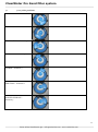
1
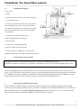
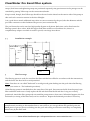
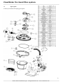
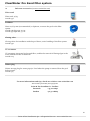
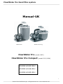
ClearWater Pro Sand filter system Manual-UK Model 1002 Model 1001/1044 ClearWater Pro (model 1002) ClearWater Pro Compact (model 1001/1044) ID KODE: M-1001.2014 ID KODE: M-1044.2014 ID KODE: M-1002.2014 1 Swim & Fun Scandinavia Aps – [email protected] – www.swim-fun.com ClearWater Pro Sand filter system Table of contents: 1. General 2. Parts 3. Connecting to power source 4. Setup of the sand filtering system 5. The first usage 6. The backwash procedure 7. User instructions for 7-way valve 8. Maintenance 9. Troubleshooting 10. Spare parts 11. Accessories 1. 2 4 5 5 9 10 11 13 16 17 18 General The sand filtering system consists of a filter tank made in one unwelded piece of high quality polypropylene. The material is completely resistant to corrosion and all standard pool chemicals on the market. The filtering device is equipped with an outlet socket, a pressure gauge and built-in components such as a sieve bottom, which provides a uniform distribution of water, and a stable PE-separation wall between the filter and the clean water storage tank. The sand filter is ready for use and is delivered with a user-friendly seven-way valve which is integrated in the filter lid, a CE/GS-approved self-sucking pump with a pre-filter, as well as a platform for final assembly on the usage site. The sand filtering system is manufactured from first-class components in accordance with strict technical standards. Additionally, there is a concluding product inspection and an automatic pressure test of each individual filter. This manual contains guidance for setup, installation, startup, maintenance, repair and service. Note: Correct installation, usage and maintenance of your sand filtering device is your guarantee for achieving a good filtering quality and a long life for the device. We strongly recommend that you follow the instructions in the accompanying manual. The safety notes and references in the manual shall be adhered to at all times. 1.1 The references in the manual In this manual the references below have the following meanings: Warning: This reference is used in cases where personal injury or other accidents can occur if the user manual, the operating instructions and usage procedures are not fully or to any extent adhered to. Observe: This reference is used in cases where damage to the product can occur if the user manual, the operating instructions and usage procedures are not fully or to any extent adhered to. Note: This reference is used to bring attention to specific information. 2 Swim & Fun Scandinavia Aps – [email protected] – www.swim-fun.com ClearWater Pro Sand filter system 1.2 Warranty The manufacturer guarantees safe usage and products liability under these specific terms: The sand filtering system is installed and used in accordance with the instructions in the manual. Only original spare parts may be used. Wear is not covered by the warranty. Wear includes O-rings Pressure gauge Pre-filter sieve with handles Perviousness that arises between hoses and hose connections in general. 1.3 Safety notes The sand filtering pump is constructed and tested in accordance with the European standard EN 60335-2-41, Safety standards for electrical appliances and similar utensils – specific requirements for electrical pumps. It is manufactured and tested by the manufacturer who also supplies the technical stamp of approval. In order to maintain this mint condition and ensure that the product is used safely, the user should pay close attention to the notes and the technical information in the manual. If there be signs that safe usage of the product no longer can be guaranteed, the product should be quickly disconnected and ensured against hazardous usage. Such is the case if: 1.4 the product is visibly damaged the product does not seem to function the product has been stored over a long period of time under poor conditions. Transportation damage We have packed your sand filtering device carefully and professionally before delivery. Please remember to check that the package is undamaged and that the delivery is complete. External transportation damage should swiftly be reported in writing to the haulier, and secondarily to the shipper, in order for you, the consignee, to avoid a problematic situation. The manufacturer is not responsible for damage to the product if it has not been used in accordance with the instructions in the accompanying manual. 3 Swim & Fun Scandinavia Aps – [email protected] – www.swim-fun.com ClearWater Pro Sand filter system 2 Parts Seven-way overhead valve with a lid to the filter tank, 1 pressure gauge, 1 large pressing ring for the lid, filter tank (not in image), 1 black connection hose between filter tank and pump, 2 straps, manual (not in image), pump, 2 mounting screws with clamping unit and nut for the pump, platform for the pump, 2 black hose valves of 32/38 mm, 2 grey special adaptors with flat gaskets for Intex pools (model 1002) – see photos 2.1 and 2.2 Photo 2,1 Photo 2,2 Observe: If you unfasten the filter tank's two threaded sockets, the water should be disconnected from both the suction hose and the pressure hose so that water cannot escape over the pump itself. There is no guarantee against damage from flooding of the pump. 2.1 Technical information – ClearWater Pro (1002) / ClearWater Pro Compact (1001/1044) Sand filtering device (filter tank Ø400 mm) with a self-sucking pump with a pre-filter, seven-way overhead valve, pressure gauge and filter platform. The filter is preset for usage with integrated UV light unit, pool heater and dust filter. ClearWater Pro 1002 Requirements Capacity at working pressure of 0.4 bar 7 000 litres/hour Working overpressure Voltage Output (P2) Protection class Wire length including socket Maximum surrounding temperature Amount of sand Measurements (L x B x H) Weight (without filter sand) ClearWater Pro Compact 1001 - 1044 Capacity working pressure 0.4 bar 1001 Capacity working pressure 0.4 bar 1044 Specifikationer 1.5 bar 230 V 1 N-AC / 50 H 550 watts Working overpressure Voltage Output (P2) 1001 Output (P2) 1044 1,5 bar 230 V 1 N-AC / 50 H 450 watt 250 watt IP X5 1.5 metres 35°C Protection class Wire length including socket Maximum surrounding temperature IP X5 1,5 meter 35 °C circa 25 kg 600 x 490 x 700 mm 15 kg Amount of sand Measurements(L x B x H) ca 12 kg 600 x 490 x 430 mm 12 kg Weight (without filter sand) 5 500 litres/hour 4 500 litres/hour 4 Swim & Fun Scandinavia Aps – [email protected] – www.swim-fun.com ClearWater Pro Sand filter system 2.2 Installation diagram 1. Filter tank 2. Pump 3. Attachment hose between six-way valve and pump 4. 7-way overhead valve 5. From pool (uncleansed). Shown with practical lock valve installed on the pump's hose (not included) 6. To the pool (cleansed water). Shown with practical lock valve installed on the hose after the sand filter (not included) 7. Backwash for emptying unclean water. 8. Filter opening (with pressing ring) 9. Pressure gauge 10. Outlet valve – placed on the side. 11. Bottom outlet/open outlet channel 12. Two openings to UV light and / or water heater Aggregate diagram for the entire sand filtering device 3. Connecting to power source Observe: At flexible mains connection to an electrical power source, HO5RN-F is used (indoors) or HO7RN-F (outdoors).The smallest diameter is 1,5 mm or something close to it. At permanent connections with wires, only plastic-coated NYM wires or wires of similar quality may be used. When the filtering system is used outdoors, it needs to be connected to an outdoor power source of 230 V 1 N–AC 50 HZ. The power source must be at least 3.5 m from the edge of the pool and must always be installed by a qualified electrician. Installation with filter sand and flexible pool hoses or PVC pipe. Note: The power source must always have earth connection and be connected to an HFI/HPFI-device. 4. Setup of the sand filtering system Observe that the smallest distance between the edge of the pool and sand filtering pumps with ordinary 220/230 V power supply should be at least 3.5 metres according to the installation standard C15-100.The sand filter should be placed on a steady and entirely smooth (!)surface of at least 60 x 60 cm. The site should have a draining surface consisting of pebbles, crushed concrete or the like. 5 Swim & Fun Scandinavia Aps – [email protected] – www.swim-fun.com ClearWater Pro Sand filter system The pump is self-sucking but should always be positioned below the waterline and in level with the poolbottom so that the water flows to the pump of its own accord. This will considerably relieve the pressure on the pump and extend its life. Insert the two enclosed stainless screws, each with a tension pulley, into the drilled holes of the filter platform and fasten the pump with the nuts (the mounting piece to the suction hose/plexiglas lid should be directed towards the left). See photos 4.a and 4.b. Photo 4.a Position the pump so that the mounting piece to the suction hose/plexiglas lid is directed towards the left viewed from the side where the pump is standing at the front on the platform. The overhead valve's grey pump connection ”from pump” points forward in the direction towards the pump (photo 4.b). In this connection, also check that the lid of the outlet valve at the bottom of the filter tank is fastened. Photo 4.b 4.1 Replenishment of filter materials Open the pressing ring at the filter tank's opening and take off the filter lid. Having done this, check that the foundation plate and the separator wall inside the filter tank are correctly positioned. Note that the bars on the foundation plate continue to the bars of the filter tank's inner wall. Thereafter, the separator plate should also be placed in these wire bars so that the upper edge of the separator plate is lying flat against the edge of the filter tank. See photos 4.1a and 4.1b. Photo 4.1a Photo 4.1b Photo 4.1a (A plastic clamp is included for tightening the pressing ring) 6 Swim & Fun Scandinavia Aps – [email protected] – www.swim-fun.com ClearWater Pro Sand filter system Photo 4.1c Photo 4.1d Observe: In order to protect the filter tank and the foundation plate against possible damage, ALWAYS fill the filter tank with 20-30 cm of water before the filter sand is poured into the tank! Photo 4.1c + 4.1d. Filter bottom with small grooves Filter chamber Outlet valve under filter bottom Separator wall between the filter chamber and the cleansed water Inlet from the filter chamber Observe: Anchor point. This is where the filter lid should slot into place. Diagram over the inside of the filter tank when the lid has been removed. The filter material is poured into the filter tank thus: Model 1001/1044 Pro Compact is filled with 10-12 kg sand while Model 1002 Pro is filled with circa 25 kg. The filter material consists of special quartz sand that has been rinsed, silted up and burnt. This filter sand must be ordered separately. Alternately, zeolite or crushed glass can be used as filter material. Seal the filter tank carefully. First, remove any grit and grime from the sealing jointing and grease the O-ring with a bit of Vaseline if needed. This extends its life. Observe: Make sure that there is no excess filter sand in the filter tank and that there is no sand in the clean water storage tank as this can result in sand at the bottom of the swimming pool. 7 Swim & Fun Scandinavia Aps – [email protected] – www.swim-fun.com ClearWater Pro Sand filter system Position the filter lid on the back edge of the filter tank so that the grey pump connection ”from pump” in the seven-way valve is pointing forward. Check that the lid is tightly sealed all the way round. Connection to the attachment hose from the pump Opening in the lid towards UV light ”Anchor point” on the lid Filter lid ”Anchor point” at the clean water storage tank Gasket Clean water storage tank Diagram over the exterior of the filter tank 4.2 Interconnection of the sand filtering system First, grease the three valves on the filter tank with a little Vaseline so as to facilitate easy attachment of the hose. Then attach a black hose valve with an O-ring on the pump's exit side (at the top) and fasten it. Grease, if you will, with a little Vaseline the pump's attached hose valve. Now slot the attachment hose and the grey pump connection into place on the pump and the filter tank respectively. Fasten the hoses tightly with the accompanying tightening straps and check that the hose is secured. See photo 4.2 Photo 4.2 Thereafter, the filtering system is connected to the pool (in this case flexible connection with pool hoses) A pool hose is attached to the pool's skimmer (or the pool's output connection) and is connected in the same way to the pump's input connection (the suction side). This hose transports the uncleaned pool water to the filtering system. Another pool hose, which leads the cleansed water back to the pool, is attached between the filter lid's connection ”to pool” and the pool's input connection. A third hose can also be attached to the filter lid (to drain) with the other end of it placed by an outflow. All three pool hoses are attached with tightening 8 Swim & Fun Scandinavia Aps – [email protected] – www.swim-fun.com ClearWater Pro Sand filter system straps. (Pool hoses and tightening straps are purchased separately) Any perviousness in the passages can be remedied by putting Teflon tape on the connections/threads. Keep in mind, though, that Teflon tape should not be used on the thread on the suction side of the pump as this can lead to excessive tension in the clear Plexiglas. It is a good idea to attach additional stop valves as extra accessories by the pool, after the skimmer and the pool inlet connection as this facilitates the process. (www.swim-fun.dk). The pool hoses that can be used are high-quality Ø32mm or Ø38 mm. Both sizes can be fitted onto the filtering system's hose valves. With the largest sand filter model 1002 ClearWater Pro, there is a complimentary adaptor set which is used for special, extra-large Intex hoses. 4.3 Installation example Return channel coupling Closing valves To pool From pool Pool Firm surface Drain Earthed power source 5 The first usage The filtering system is ready for use when the filter tank has been filled in accordance with the instructions, and the hoses also have been correctly attached. Note: First there is a so-called ”backwash” to avoid grit and grime leaking into the pool when the filtering starts. (see section 6 – The backwash procedure). If the filtering system is installed above the water line of the pool, first unscrew the lid from the pump's prefilter and dilute with water. Gently replace the lid and check that the lid and the O-ring are correctly positioned. Attach the filter pump and wait until the pump starts to draw water. When this happens, the first backwash (re-rinsing of the filter sand) can be carried out. Repeat the backwash procedure if necessary. NOTE: The filter sand should be manufactured according to the standard DIN 12094. Filter sand that is manufactured according to this standard has no more than 10 per cent grit below the specified grain size. Small pieces of grit are prone to whirling into the pool and resting on its bottom until they are completely rinsed away by the filter tank. 9 Swim & Fun Scandinavia Aps – [email protected] – www.swim-fun.com ClearWater Pro Sand filter system 5.1 Filter time The water in a swimming pool should be cleansed through the filter tank 2-4 times a day, depending on how much water the pool holds and the cleansing capacity of the filtering device. If the weather and the pool water is warm there is always a need for increased filtering and chemical cleansing of water. During warm periods the pool is likely to be used more frequently which further increases the demands on cleansing of water. We recommend the use of a simple, cheap outdoor timer, enabling automatic switching on and off of the pump. It is usually completely unnecessary to run the pump around the clock, and regularly scheduled breaks where the motor can cool off extends the life of the pump. Example: Let the timer program the pump to run for four hours, then let it rest for one to two hours, allowing it to cool down. Keep repeating the the procedure, running it for four hours and letting it rest. The number of hours should be related to the pool's size and other conditions. 5.2 Filtering Dirty substances from the pool water are accumulated in the filter sand. The effect of the filtering is also markedly increased if there is a regular addition of flocculating agents to the pool water, either in fluid form or, more preferably, through flocculating rods that are placed in the pool's skimmer. The flocculating agent accumulates tiny floating particles into larger ones that can easily be caught in the filter. 6. The backwash procedure The filter sand must be cleansed from dirty particles regularly. This is done using re-rinsing, also called ”backwash”, where the water current is ”turned” in the filter tank and the dirty particles are washed off the sand. The unclean re-rinsing water is diverted via the filter tank's ”Waste”-valve and is led to the nearest outflow. Observe: The pump should ALWAYS be turned off before changing the filter position with the seven-way handle. NEVER change the handle while the pump is running as this can damage the overhead valve and bring sand into the pool! Turn off the filter pump! Place the handle of the filter tank in position 4 - ”backwash” Make sure a hose is attached to the ”Waste”-valve, or the water will escape from the filter tank. If needed, there is a special, compact back wash hose that can be purchased. (www.swim-fun.com) Turn on the pump again and let it run until the pumped-out water shifts colour from opaque and dirty to clear and clean. This could take 1-3 minutes. Turn off the pump. Set the handle in position 2 ”Rinse”. This will cleanse the valve head from grit that would otherwise end up in the pool. Turn on the pump and let it run for about a minute while more water is led to the outflow. 10 Swim & Fun Scandinavia Aps – [email protected] – www.swim-fun.com ClearWater Pro Sand filter system Turn off the pump. et the handle to position 1 ”Filtration” Turn on the pump. he filter system is now ready for use again. 7. User instructions for 7-way valve The filtering system is equipped with a seven-way valve on the lid of the filter tank so that the cleansing procedure can be controlled manually. Press the handle down with the palm of your hand and turn it to the desired position. The following working positions are possible: FILTERING Water from the pool is pressed through the filter tank and pumped back to the pool. CLEANSING Water from the pool is pressed through the filter tank and is pumped back to an external outflow. Grit in the overhead valve is cleansed. CIRCULATION Water from the pool is returned to the pool without filtering. BACKWASH Water from the pool is pressed through the filter tank and is pumped back to an external outflow. Cleansing of dirty particles in the filter sand. CLOSED All valve outlets are closed and the water cannot circulate. The lid can thereby be lifted off the filter tank. EMPTYING Water is sucked from the pool without filtering and is pumped to an external outflow. WINTER STORAGE This position is used when the sand filter and the pump have been emptied and detached from the pool and are kept frost-free during the winter. The position relieves the pressure on the spring-loading and the overhead valve's gasket. Observe: Keep in mind that the dirty return water should be easy to divert before the backwash procedure starts – remember the backwash hose! Also, keep in mind not to interrupt the backwash and the ensuing rinsing until they are completely carried out! Check in advance that there is sufficient water in the pool to carry out these procedures. Observe: The seven-way handle on the filter tank's overhead valve must NEVER be used in an attempt to lift the filter tank!! The seven-way handle is not constructed for this purpose and such an attempt may cause the handle to break! 11 Swim & Fun Scandinavia Aps – [email protected] – www.swim-fun.com ClearWater Pro Sand filter system 7.1 7-way valve positions FILTERING – Position 1: BACKWASH – Position 2: CIRCULATION – Position 3: CLEANSING – Position 4: CLOSED – Position 5: EMPTYING – Position 6: WINTER STORAGE – Position 7: 12 Swim & Fun Scandinavia Aps – [email protected] – www.swim-fun.com ClearWater Pro Sand filter system 7.2 Filter backwash The filtering continually causes accumulation of dirty particles in the filter sand. This accumulation causes an increasing resistance in the filter tank as the water is pressed through the filter material. The pressure gauge shows the pressure inside the tank. If the pressure should rise by circa 0.2-0.3 bar above the original pressure measurement, when the filter sand was new and clean, the filter needs a backwash. NOTE: In order to provide good hygienic conditions in the filter tank and generally optimal functioning of the filter, a backwash of the filter should be carried out at least once a week – regardless of how often the filter has been used during the period and how much dirt has been accumulated in the filter material (increased pressure on the pressure gauge). During warm periods and periods of increased bathing activity, at the start of the pool season or when the water is opaque, or if the atmosphere is more than usually polluted by pollen, leaves, insects etcetera, a backwash should be carried out several times a week. 8. Maintenance Interval Weekly Annual Action Clean the per-filter basket. Carrry out the backwash regardless of how dirty the filter is. Prepare the filtering system for the winter before the frost sets in. Change the filter sand during pre-season before the sand filter is used again. Take the following steps to clean the pre-filter basket: 1. 2. 3. 4. 5. Turn off the power and pull out the plug. Close the stop valves on the pool hoses or block the passage of water from the pool side in another efficient way. Set the filter to position 6 – closed. Unscrew the connection lid from the transparent pre-filter lid, remove the pump's lid and take out the pre-filter basket. Clean the basket and put it back in the pre-filter. Attach the transparent pre-filter lid and screw the connection lid into place again. Open the stop valves so that the water once again can flow to and from the filtering system. Put the plug in the socket and swith on the power. Observe: The pump may not be used without a basket in the pre-filter as the pump otherwise can be clogged or destroyed by grass, leaves or other material. In such cases, the warranty will be void. 13 Swim & Fun Scandinavia Aps – [email protected] – www.swim-fun.com ClearWater Pro Sand filter system 8.1 When installing filtering systems in pump well close to the pool The well should be large enough to enable all maintenance on the filtering system to be carried out unobstructed. All other instructions are given under 4.2 Observe: At the installation it is important that the pump well is not directly exposed to splashing water from the pool or rain water. Observe: The well should be well-ventilated to avoid condensation that over time could damage the pump through corrosion. Note: The manufacturer is not responsible for damage stemming from installation and usage in areas that are intended for housing, nor for damage stemming from poor floor draining or other drainage systems. 8.2 Installation in plant room Requirements for plant room: Power source: Floor drainage: 230V The floor should have an inclination that will allow water to be led away and discharged. Open drainpipe connection: The diameter of the drainpipe should be at least Ø100 mm Bottom tank for pump: If the drainpipe is higher than the re-rinsing valve, a bottom tank of at least 0.6 x 0.6 x 0.6 m should be built. A suitable pumping device should also be positioned at the installation site. The floor of the plant room may not be higher than the swimming pool's water line. If the filtering device is positioned above the water line, a return pipe stop must be attached to the suction hose from the pool. The difference in height may never exceed 1.5 m. 8.3 Requirements for the building The floor of the plant room should at a minimum have a water-repellent covering and incline towards the drain. The room's ventilation must be adequate. 8.4 Space requirements The sand filtering device requires an area of: 600 x 800 x 1250 mm (Breadth x Depth x Height) 8.5 Important installation information We recommend the use of PVC pipe and PVC connections when carrying out the installation. (They must always be installed by a professional). 14 Swim & Fun Scandinavia Aps – [email protected] – www.swim-fun.com ClearWater Pro Sand filter system Alternatively, PE pipe is used, if placed subterraneanly. Note that a ball valve must be attached to the suction hose with raw water and another attached to the pressure hose with cleansed water. The sand filtering device must be kept completely erect (on a flat level). NOTE: If the suction hose is short, the suction time will be reduced and the pump's capacity increased. Observe: The hoses and the pipes must be completely impervious as the pump's capacity will be impaired if air is allowed into the suction hose. This may also be harmful. Electrical installation must be carried out by a qualified electrician who has to consider the above-mentioned safety zone of the pool. 8.6 Waste You can help preserve our environment. Always dispose of consumed electrical equipment correctly at your local recycling station. 8.7 Winter storage When the swimming pool is prepared for winter, the filter and the pump must always be entirely emptied, detached and stored in a dry and frost-proof room before the first frost arrives! Otherwise, there is a risk of frost damage that is not covered by the warranty. On the same occasion, set the seven-way handle to the winter position (position 7), as this relieves the pressure on the handle's 15 Swim & Fun Scandinavia Aps – [email protected] – www.swim-fun.com ClearWater Pro Sand filter system 9. Troubleshooting Problem The pressure gauge shows pressure in excess of 1.0 bar Pressure is too low Air in the pump's pre-filter Cause Dirty filter sand Solution Carry out a backwash The pre-filter basket is dirty The gasket around the sevenway valve is dirty and leaky Clean the pre-filter basket Detach the seven-way valve from the filter lid and clean the gasket. Water escapes from the backwash valve The gasket around the sevenway valve is dirty and leaky. Grit in the gasket. Detach the seven-way valve from the filter lid and clean the gasket. Pervious filter Damaged gasket Examine the gasket and exchange it for a new one if necessary. The pump is not running The filter system has been deactivated by the filter timer or a filter control Examine the settings The plug is not connected Connect the plug The HFI device turns the pump off Turn on the HFI device again. If it immediately turns itself off again, it means the pump or the HFI device is damaged. Damaged pump motor Replace the pump. If the filter sand is new there are other pieces of grit that have returned to the filter. Carry out repeated backwash until the backwash return water is totally clear. Sand in the seven-way valve (residue from backwash). The separator wall in the filter tank is not correctly positioned. Set the filter to the rinse function and pump water to the outflow for about 30 seconds. Check that the separator wall is correctly positioned. The foundation plate is damaged. Exchange the damaged plate for a new one. Sand in the pool Repair of the filter pump may only be carried out by a qualified professional firm or the warranty will be void. 16 Swim & Fun Scandinavia Aps – [email protected] – www.swim-fun.com ClearWater Pro Sand filter system 10 Spare parts Contact your dealer for buying spare parts 17 Swim & Fun Scandinavia Aps – [email protected] – www.swim-fun.com ClearWater Pro Sand filter system 10 Relevant accessories (see www.swim-fun.com) Filter sand Filter sand, 25 kg. Article 1536 Poolhose Hose set, Ø32 mm (recommended) or Ø38 mm, connects the pool to the filter system. Article 1582 Ø32 mm, 6,6 m. Article 1542 Ø38 mm, 9,0 m. Closing valve Closing valves for installation with the pool hoses, easier handling of the filter system. Article 1556 UV treatment UV treatment, integrated in the sand filter, enables the removal of floating algae in the water without the use of chemicals. Article 1005 Winter plug Winter storage plug for return pipe jet. Used when the pump is removed from the pool before winter. Article 1519 For more informations and tips, check our website: www.swim-fun.com This manual is protected by the copyright law Swim & Fun Scandinavia – hotline: Denmark +45 7022 6856 Sweden +46 771 188819 18 Swim & Fun Scandinavia Aps – [email protected] – www.swim-fun.com