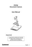
1
MARCH 1998
MC165A-R2
Global Teleconnect Kit
CUSTOMER
SUPPORT
INFORMATION
Order toll-free in the U.S.: Call 877-877-BBOX (outside U.S. call 724-746-5500)
FREE technical support 24 hours a day, 7 days a week: Call 724-746-5500 or fax 724-746-0746
Mailing address: Black Box Corporation, 1000 Park Drive, Lawrence, PA 15055-1018
Web site: www.blackbox.com • E-mail: [email protected]
FCC STATEMENT
FEDERAL COMMUNICATIONS COMMISSION
AND
INDUSTRY CANADA
RADIO FREQUENCY INTERFERENCE STATEMENTS
This equipment generates, uses, and can radiate radio-frequency energy, and if not
installed and used properly, that is, in strict accordance with the manufacturer’s
instructions, may cause interference to radio communication. It has been tested
and found to comply with the limits for a Class A computing device in accordance
with the specifications in Subpart B of Part 15 of FCC rules, which are designed to
provide reasonable protection against such interference when the equipment is
operated in a commercial environment. Operation of this equipment in a
residential area is likely to cause interference, in which case the user at his own
expense will be required to take whatever measures may be necessary to correct
the interference.
Changes or modifications not expressly approved by the party responsible
for compliance could void the user’s authority to operate the equipment.
This digital apparatus does not exceed the Class A limits for radio noise emission from
digital apparatus set out in the Radio Interference Regulation of Industry Canada.
Le présent appareil numérique n’émet pas de bruits radioélectriques dépassant les limites
applicables aux appareils numériques de la classe A prescrites dans le Règlement sur le
brouillage radioélectrique publié par Industrie Canada.
1
GLOBAL TELECONNECT KIT
NORMAS OFICIALES MEXICANAS (NOM)
ELECTRICAL SAFETY STATEMENT
INSTRUCCIONES DE SEGURIDAD
1. Todas las instrucciones de seguridad y operación deberán ser leídas antes de
que el aparato eléctrico sea operado.
2. Las instrucciones de seguridad y operación deberán ser guardadas para
referencia futura.
3. Todas las advertencias en el aparato eléctrico y en sus instrucciones de
operación deben ser respetadas.
4. Todas las instrucciones de operación y uso deben ser seguidas.
5. El aparato eléctrico no deberá ser usado cerca del agua—por ejemplo, cerca
de la tina de baño, lavabo, sótano mojado o cerca de una alberca, etc..
6. El aparato eléctrico debe ser usado únicamente con carritos o pedestales que
sean recomendados por el fabricante.
7. El aparato eléctrico debe ser montado a la pared o al techo sólo como sea
recomendado por el fabricante.
8. Servicio—El usuario no debe intentar dar servicio al equipo eléctrico más allá
a lo descrito en las instrucciones de operación. Todo otro servicio deberá ser
referido a personal de servicio calificado.
9. El aparato eléctrico debe ser situado de tal manera que su posición no
interfiera su uso. La colocación del aparato eléctrico sobre una cama, sofá,
alfombra o superficie similar puede bloquea la ventilación, no se debe colocar
en libreros o gabinetes que impidan el flujo de aire por los orificios de
ventilación.
10. El equipo eléctrico deber ser situado fuera del alcance de fuentes de calor
como radiadores, registros de calor, estufas u otros aparatos (incluyendo
amplificadores) que producen calor.
11. El aparato eléctrico deberá ser connectado a una fuente de poder sólo del
tipo descrito en el instructivo de operación, o como se indique en el aparato.
2
NOM STATEMENT
12. Precaución debe ser tomada de tal manera que la tierra fisica y la polarización
del equipo no sea eliminada.
13. Los cables de la fuente de poder deben ser guiados de tal manera que no
sean pisados ni pellizcados por objetos colocados sobre o contra ellos,
poniendo particular atención a los contactos y receptáculos donde salen del
aparato.
14. El equipo eléctrico debe ser limpiado únicamente de acuerdo a las
recomendaciones del fabricante.
15. En caso de existir, una antena externa deberá ser localizada lejos de las lineas
de energia.
16. El cable de corriente deberá ser desconectado del cuando el equipo no sea
usado por un largo periodo de tiempo.
17. Cuidado debe ser tomado de tal manera que objectos liquidos no sean
derramados sobre la cubierta u orificios de ventilación.
18. Servicio por personal calificado deberá ser provisto cuando:
A: El cable de poder o el contacto ha sido dañado; u
B: Objectos han caído o líquido ha sido derramado dentro del aparato; o
C: El aparato ha sido expuesto a la lluvia; o
D: El aparato parece no operar normalmente o muestra un cambio en su
desempeño; o
E: El aparato ha sido tirado o su cubierta ha sido dañada.
3
GLOBAL TELECONNECT KIT
TRADEMARKS USED IN THIS MANUAL
AT&T and Merlin are registered trademarks of American Telephone and
Telegraph Company.
Velcro is a registered trademark of Velcro USA Inc.
Duracell is a registered trademark of P.R. Mallory.
CrossTalk is a registered trademark of Digital Communications Associates,
Inc.
ProComm is a registered trademark of DATASTORM TECHNOLOGIES,
INC.™
Any trademarks mentioned in this manual are acknowledged to be the property of the
trademark owners.
4
CONTENTS
Contents
Chapter
Page
1. Introduction ....................................................................................................6
1.1 Overview....................................................................................................6
1.2 What’s Included .......................................................................................6
2. Components ....................................................................................................8
2.1 Standard Tools and Accessories ..............................................................8
2.2 Carrying Case..........................................................................................10
2.3 Phone Coupler II. ..................................................................................11
2.4 International Power Plug Adapters.......................................................12
2.5 International Telephone Adapters .......................................................15
3. Operation ......................................................................................................18
3.1 When Using a Power Adapter ...............................................................18
3.2 When Using a Telephone Adapter .......................................................18
3.3 Other Countries the Adapters Work In ................................................20
MODEM DEFENDER........................................................................................23
Specifications .................................................................................................25
Introduction...................................................................................................26
Operation.......................................................................................................28
Using the Modem Defender to Test an Unknown Line ..................28
Using the Modem Defender-I Tax Impulse Filtering Feature .........30
Using the Modem Defender-I in the United Kingdom....................31
Correcting the “Reversed Polarity” (Yellow LED) Condition ..........31
PHONE COUPLER II.......................................................................................32
Specifications .................................................................................................33
Introduction...................................................................................................34
Overview ..............................................................................................34
What’s Included..................................................................................34
The Phone Coupler II ........................................................................34
Operation.......................................................................................................36
Installing/Replacing the Battery .......................................................36
Installing the Coupler ........................................................................37
Tips for Better Performance ..............................................................39
Manual Dialing and Modem Configuration ................................................41
Troubleshooting............................................................................................44
Glossary ..........................................................................................................46
5
GLOBAL TELECONNECT KIT
1. Introduction
1.1 Overview
The Global Teleconnect Kit gives you the power to connect your portable
computer and modem worldwide. This Kit contains essential connectivity
tools, plus the most popular international power-plug and telephone
adapters. A durable nylon carrying case, with a protective pocket for a
PCMCIA modem card and room for additional accessories, is also included.
As you use your new adapters, please keep the following precautions in mind.
• Being able to connect physically to a power outlet is only one
consideration when connecting to a foreign power source. Be sure you
know what type of power is present at a wall receptacle before connecting
your portable computer.
• NEVER connect any computer or electrical appliance designed to use only
AC power to DC power or severe damage will result.
1.2 What’s Included
Your Global Teleconnect Kit should contain the following items. If any of
these items are missing, please contact your supplier.
Standard Tools and Accessories
• Global Teleconnect Kit Carrying Case
• Phillips Screwdriver
• Flashlight with Magnifier
• Compact Printer Cable, 3-ft. (0.9-m)
• Retractable RJ-11 Cord
• Modem Defender
• 5" RJ-11 Adapter Cord
6
CHAPTER 1: Introduction
Phone Coupler II
• High-Speed Modem Coupler
• Nylon Case
• 9-Volt Alkaline Battery
• Merlin® Handset Adapter
International Power Adapters
• GB/Africa/Hong Kong
• Europe/Middle East
• Great Britain
• North/South America
• Australia/New Zealand
• 3-to-1 Power Tap (US)
• 3-to-2 Prong Ground (US)
International Phone Adapters
• French Modular
• German F/N (Universal) Adapter
• Inline Adapter
• UK Inline Adapter (BT-431A Type)
• Line-Switching Adapter
• Modular T-Adapter (US)
• Polarity-Reversing Adapter
• Japan Modem Adapter
• Italy/Turkey Modular Adapter
7
GLOBAL TELECONNECT KIT
2. Components
This chapter gives you an in-depth look at the uses for the various
components of the Global Teleconnect Kit.
2.1 Standard Tools and Accessories
Component
Use
❶ Phillips Screwdriver Attaching or removing
computer covers, cable
connectors, etc.
❷ Hand-Held Flashlight w/Magnifier
Examining hard-to-see objects.
❸ Compact Printer Cable
Connects the printer to the
computer’s printer port. The
cable is 3 feet (0.9 m) long.
❹ Modem Defender A telephone-line tester that
protects your computer’s
modem from unsafe telephone
lines. See the Modem Defender
manual (starting on page 22)
for more information.
8
Retractable RJ-11 Cord
Not pictured.
5" RJ-11 Adapter Cord
Not pictured.
CHAPTER 2: Components
❶
❸
❷
❹
TO LINE
OK
+-
TEST
M
OD
EM
DE
FE
ND
ER
TO MODEM
Figure 1. Standard Tools and Accessories.
9
GLOBAL TELECONNECT KIT
2.2 Carrying Case
The Global Teleconnector Kit carrying case is constructed of heavy-duty
nylon. The case, about the size of a shaving kit—approximately 2"H x
10"W x 8"D (2.1 x 25.4 x 20.3 cm)—is specifically designed to accommodate
all of the accessories in the Teleconnector Kit, and allows additional room for
some of your own favorite tools.
TOOLS &
ADAPTERS
POCKET
OPTIONAL ACCESSORIES
POCKETS (SUITABLE
FOR PCMCIA MODEM
CARD)
PHONE COUPLER II
MODEM COUPLER
VELCRO STRIP
TO SECURE PHONE
COUPLER II
Figure 2. The Global Teleconnect Kit Carrying Case.
10
CHAPTER 2: Components
2.3 Phone Coupler II
The Phone Coupler II is a high-speed modem coupler. With it, the modem
in your portable computer can connect to virtually any wired-in telephone
where no direct access is otherwise available to the telephone line (for
example, at a pay phone or with most cellular phones). When properly
installed and used, the Phone Coupler II supports modem fax or data
transmissions at transfer rates up to 14,400 bps. Speed may vary, depending
on your type of modem, telephone line conditions, and the type of
communications software used. (Transmission type and transfer rate are set
by your modem and communications software, not by the Phone Coupler II.)
Figure 3. Phone Coupler II.
11
GLOBAL TELECONNECT KIT
The Phone Coupler II should fit snugly on the telephone headset (earpiece
to small coupler pickup and mouthpiece to large coupler speaker) so that no
outside noise will be transmitted. During fax or data transmission, the
Coupler converts the output signal from your modem into audible tones,
which the handset microphone picks up. Similarly, during fax or data
reception, the Coupler converts audible tones from the handset earpiece into
signals that the modem understands. For the best transmission and reception
results, the Coupler has a three-position slide switch that adjusts to
compensate for varying audio levels found on phone systems throughout the
world.
The Coupler is powered by a self-contained 9-volt alkaline battery (supplied).
The unit comes with its own zippered carrying case, which has a Velcro® strip
to attach to the inside of the Global Teleconnector Kit’s carrying case. In
addition, an AT&T® Merlin handset adapter disk is supplied. This disk adapts
the wedge-shaped handset mouthpiece of the Merlin telephones to the Phone
Coupler’s speaker. For specific information about the Phone Coupler II, refer
to pages 32 through 47.
2.4 International Power Plug Adapters
The various power plug adapters included in your Kit are pictured in this
section. Read the information to the right of each illustration to determine
which adapter is right for your particular application. Once you’ve
established which adapter you’ll be using, read Section 3.1, When Using a
Power Adapter—it contains important safety information.
3-to-2 Prong Grounding Adapter
Used to provide a ground connection
when connecting to a 2-prong (ungrounded) receptacle.
Caution: The loop at the bottom of this
adapter must always be screwed to a
grounded wall receptacle. Electronic
equipment that comes with a 3-prong
power plug requires grounding for
safety purposes.
12
CHAPTER 2: Components
GB/Africa/Hong Kong/Singapore Adapter
This adapter accepts 2- or 3-prong
power plugs from the US and Europe.
It plugs into 3-prong (grounded)
power receptacles found in Great
Britain, Africa, Hong Kong, Ireland, and
Singapore.
Europe/Asia/Middle East/Africa Adapter
This adapter accepts 2-prong power
plugs from the US and Great Britain.
It plugs into 2-prong power
receptacles found in Europe, Asia, the
Middle East, parts of Africa, and the
Caribbean.
Great Britain (certain areas) Adapter
This adapter accepts 2-prong power
plugs from the US and Europe.
It plugs into 2-prong power
receptacles found in certain areas of
Great Britain.
13
GLOBAL TELECONNECT KIT
North and South America/Caribbean/Japan Adapter
This adapter accepts polarized 2-prong
power plugs from the US and other
North- and South-American countries.
It plugs into non-polarized 2-bladed
power receptacles used in North and
South America, the Caribbean, and
Japan.
Australia/New Zealand/Fiji/China Adapter
This adapter accepts 2-prong power
plugs from the US, Great Britain, and
Europe. It plugs into polarized
2-bladed power receptacles used in
Australia, New Zealand, Fiji, and China.
3-to-1 Power Tap
This adapter plugs into a polarized or
non-polarized 3-prong (grounded) US
power receptacle to provide power to
up to three US power cords.
14
CHAPTER 2: Components
2.5 International Telephone Adapters
The various telephone adapters included in your Kit are pictured on the next
page. Study each illustration carefully to determine which adapter is right for
your particular application. Once you’ve established which adapter you’ll be
using, read Section 3.2, When Using a Telephone Adapter—it contains important
application notes.
Modular Adapters
15
GLOBAL TELECONNECT KIT
Polarity-Reversing Adapter
•
•
•
•
•
•
•
•
Illustration of the sticker on the side
of the adapter. The adapter itself
has two RJ-11 connectors.
This adapter accepts a US RJ-11
modular cord plug at both ends and is
used to switch the polarity of the two
connectors on each line. Used with the
Modem Defender, this adapter
corrects the reverse-polarity condition
indicated by the Yellow warning light
on the Modem Defender.
Inline Adapter
•
•
•
•
•
•
•
•
Illustration of the sticker on the side
of the adapter. The adapter itself
has two RJ-11 connectors.
This adapter accepts a US RJ-11
modular cord plug at each end and
connects them together.
Note: This adapter has straight-through
wiring between jacks.
Line-Switching Adapter
•
•
•
•
•
•
•
•
Illustration of the sticker on the side
of the adapter. The adapter itself
has two RJ-11 connectors.
This adapter accepts a US RJ-11
modular cord plug at both ends and is
used to switch between the inner pair
of wires to the outer pair of wires. In the
UK, the outer pair of wires are sometimes used, while the inner pair is not
connected.
See Application Note 1 on page 18
for correct use of this adapter.
16
CHAPTER 2: Components
US-to-UK Modular Inline Adapter (BT-431A Type)
This adapter accepts a US RJ-11
modular cord plug at one end and
connects it to a UK BT-431A modular
cord plugged into the other end.
Note: This adapter is easily identified
by the fact that the 2 modular jacks are
different shapes (one is RJ-11, and the
other is a BT-431A).
Modular T-Adapter
This adapter accepts a US RJ-11
modular receptacle. It provides two
jacks so that two US RJ-11 modular
cords (telephone and modem) can be
connected to the same line
simultaneously.
Note: A push lever built into this adapter must be pressed in to release the
adapter from the jack it’s connected to.
See Application Note 2 on page 18.
17
GLOBAL TELECONNECT KIT
3. Operation
3.1 When Using a Power Adapter
Being able to connect physically to a power outlet is only one consideration
when connecting to a foreign power source. Be sure you know what type of
power is present at a wall receptacle before connecting your portable
computer or other electrical appliance.
Most present-day AC adapters and battery chargers for portable computers
will set themselves automatically to match the available voltage if it is within a
range of 110 to 230 volts, and 50 to 60 Hz. Some require matching the unit’s
input voltage to the voltage available by setting a 2-position switch. A few
work only with a single voltage (for example, 110-120 VAC, 60 Hz). Check
your portable computer’s owner’s manual if you are not sure which voltages
are appropriate for your computer. You may need to buy and use a voltage
converter (step-down or step-up transformer).
Be aware that in some countries in Eastern Europe and Latin America,
voltages can fluctuate widely, and you might even find DC in use. NEVER
connect any computer or electrical appliance designed to use only AC power
to DC power or severe damage will result.
3.2 When Using a Telephone Adapter
The modular telephone adapters supplied in your Global Teleconnect Kit
provide an RJ-11 jack into which you can connect your Phone Coupler II’s
modular line cord plug. Used them with modems that do not have a US
standard RJ-11 jack with which to connect.
In most countries it is illegal to directly connect to the telephone lines if your
modem has not been approved for use in that country. We don’t recommend
using our products for such illegal purposes. If you are not sure if your device
has the appropriate approvals, we recommend using the Phone Coupler II to
make your connections acoustically through the telephone handset. Check
the local laws in each country in which you will be traveling to before
attempting to directly connect your modem to the telephone systems abroad.
18
CHAPTER 3: Operation
Application Notes
1. If you are using the US-to-UK Modular Interface Adapter (BT-431A Type)
whether you are traveling to the UK or coming from the UK to any other
country, or,
If you are trying to use the Phone Coupler II with a British modem or
portable computer which has an RJ-11 type jack marked LINE or DATA (the
one you normally connect to the modular wall jack for telecommunications),
then you may have the following problem:
In all phone jacks there are 2 phone lines (Line 1 and Line 2) which are
represented by 4 wires (one phone line equals two wires). In the US and
virtually all other countries, Line 1 is the active line. In the UK, Line 2 is the
active line. In the US the two active wires are connected to the inner two of
the four wires. In the UK, they are wired to the two outer wires. If you are
traveling to the UK from any other country, you will most likely tap an
inactive line (Line 1). If you are traveling from the UK to any other country
and have a UK modem or computer then you will also most likely tap a dead
line (Line 2). The Line-Switching Adapter cross-connects the inner two wires
to the outer two wires in both directions and should be used to correct this
problem. Use this adapter if it appears that the line is not active. It may be
that the modem is trying to connect using Line 1, which may be a dead line,
and the active line is the line you are not connected to.
2. Use the Modular T-Adapter to connect both a modem and a telephone to
a US RJ-11 wall jack, as seen in Figure 4.
Figure 4. Connecting a Modem and a
Phone with the Modular T-Adapter.
19
GLOBAL TELECONNECT KIT
3.3 Other Countries the Adapters Work In
The US-to-UK Modular Inline Adapter (BT-431A Type) can also be used in
these countries:
Abu Dhabi
Ajman
American Samoa
Andaman &
Nicobar Islands
Andorra
Angola
Anguilla
Antigua and
Barbuda
Argentina
Aruba
Australia
Azores
Bahrain
Bahamas
Bangladesh
Barbados
Belarus
Belgium
Belize
Bolivia
BosniaHerzegovina
Botswana
Brunei
Cambodia
Canada
Canary Islands
Cayman Islands
Celebes
20
Channel Islands
Chile
China
Ciskei
Columbia
Corsica
Costa Rica
Cuba
Cyprus
Denmark
Dominica
Dominican
Republic
Dubai
Ecuador
Egypt
El Salvador
Eritrea
Falkland Islands
France
Fujairah
Gambia
Germany
Ghana
Gibraltar
Greece
Grenada
Guam
Guatemala
Guernsey
Guinea
Guinea-Bisseau
Guyana
Haiti
Honduras
Hong Kong
Iceland
India
Indonesia
Ireland
Israel
Italy
Jamaica
Japan
Java
Jersey
Jordan
Kalimantan
Kashmir
Kenya
Khmer Republic
South Korea
Kuwait
Laos
Lebanon
Lesotho
Liberia
Libya
Macao
Macedonia
Malawi
Malaysia
Maldives
Malta
Isle of Man
Mauritius
Melilla
Mexico
Micronesia
Montserrat
Mozambique
Myanmar
Nauru
Nepal
Netherlands
New Hebrides
New Zealand
Norway
Oman
Pakistan
Panama
Papau New
Guinea
Paraguay
Peru
Philippines
Poland
Portugal
Puerto Rico
Qatar
Romania
Sabah
CHAPTER 3: Operation
Saint Kitts and
Nevis
Saint Lucia
Saint Vincent
and Grenadines
San Marino
Sao Tome e
Principe
Sarawak
Sardinia
Saudi Arabia
Scotland
Seychelles
Sharjah
Sicily
Sierra Leone
Sinai
Singapore
South Africa
Spain
Sri Lanka
Sudan
Sulawesi
Sumatra
Swaziland
Sweden
Syria
Taiwan
Tanzania
Thailand
Tibet
Tokelau
Transkei
Trinidad and
Tobago
Turkey
Turks and Caicos
Islands
Uganda
United Arab
Emirates
United Kingdom
United States of
America
Uruguay
Vanuatu
Venda
Vietnam
Virgin Islands
(UK)
Virgin Islands
(USA)
Wales
Walvis Bay
Yemen
Zaire
Zambia
Zanzibar
Zimbabwe
The French Adapter can also be used in these countries:
Algeria
Benin
Bhutan
Brazil
Burkina Faso
Cameroon
Chad
Channel Islands
Comoro Islands
Congo
Corsica
Côte D’Ivoire
Czech Republic
Djibouti
Egypt
Equatorial
Guinea
France
French Antilles
French Guiana
French Polynesia
Gabon
Gambia
Grenadines
Guadeloupe
Guernsey
Italy
Ivory Coast
Jersey
Kashmir
Leeward Islands
Madagascar
Mali
Martinique
Mauritania
Mauritius
Micronesia
Monaco
Morocco
New Caledonia
Niger
Pakistan
Reunion
Rhodesia
Rwanda
Saint Martin
Saint Pierre and
Miquelon
Sardinia
Saudi Arabia
Senegal
Sicily
Sinai
Slovak Republic
Somalia
Syria
Tahiti
Togo
Tunisia
Vietnam
Wallis and
Futuna
21
GLOBAL TELECONNECT KIT
The Italy/Turkey Adapter can also be used in these countries:
Ethiopia
Italy
San Marino
Sardinia
Sicily
Sudan
The Japan Adapter can also be used in these countries:
Japan
Okinawa
Taiwan
The German Adapter can also be used in these countries:
Austria
22
Germany
Liechtenstein
MODEM DEFENDER
Modem Defender
FEDERAL COMMUNICATIONS COMMISSION
PART 68 REQUIREMENTS
This equipment complies with Part 68 of the FCC Rules. On the bottom of
this equipment is a label that contains, among other information, the FCC
Registration Number and Ringer Equivalence Number (REN) for this
equipment. You must, upon request, provide this information to your
telephone company. This equipment uses RJ-11 jacks. An FCC-compliant
telephone cord and modular plug are provided with this equipment. This
equipment is designed to be connected to the telephone network or premises
wiring using a compatible modular jack which is Part 68-compliant. See
installation instructions for details. The REN is useful to determine the quality
of devices you may connect to your telephone line and still have all those
devices ring when your telephone number is called. In most, but not all areas,
the sum of the RENs of all devices connected to one line should not exceed
five (5). To be certain of the number of devices you may connect to your line,
as determined by the REN, you should contact your local telephone company
to determine the maximum REN for your calling area. (NOTE: RENs are
associated with loop-start and ground-start ports. Do not use for E&M or
digital ports.) If your telephone equipment causes harm to the telephone
network, the telephone company may discontinue your service temporarily. If
possible, they will notify you in advance. But if advance notice is not practical,
you will be notified as soon as possible. You will be informed of your right to
file a complaint with the FCC. Your telephone company may make changes in
its facilities, equipment, operations, or procedures that could affect the
proper functioning of your equipment. If they do, you will be notified in
advance to give you an opportunity to maintain uninterrupted telephone
service. The telephone company may ask that you disconnect this equipment
from the network until the problem has been corrected or until you are sure
that the equipment is not malfunctioning. No user-serviceable parts are
contained in this equipment. This equipment may not be used on coin service
provided by the telephone company. Connection to party lines is subject to
state tariffs.
23
GLOBAL TELECONNECT KIT
INDUSTRY CANADA (IC) NOTICE
NOTICE: The Industry Canada (IC) label identifies certified equipment.
This certification means that the equipment meets telecommunications
network protective, operational, and safety requirements as prescribed in
the appropriate Terminal Equipment Technical Requirements document(s).
The department does not guarantee the equipment will operate to the user’s
satisfaction. Before installing this equipment, users should ensure that it is
permissible to be connected to the facilities of the local telecommunications
company. The equipment must also be installed using an acceptable method
of connection. The customer should be aware that compliance with the above
conditions may not prevent degradation of service in some situations. Repairs
to certified equipment should be coordinated by a representative designated
by the supplier. Any repairs or alterations made by a user to this equipment,
or equipment malfunctions, may give the telephone communications
company cause to request the user to disconnect the equipment. Users should
ensure for their own protection that the electrical ground connections of the
power utility, telephone lines, and internal metallic water pipe system, if
present, are connected together. This precaution may be particularly
important in rural areas. Caution: Users should not attempt to make such
connections themselves, but should contact the appropriate electricalinspection authority, or electrician, as appropriate.
NOTICE: The Ringer Equivalence Number (REN) assigned to each terminal
device provides an indication of the maximum number of terminals allowed
to be connected to a telephone interface. The termination of an interface
may consist of any combination of devices subject only to the requirement
that the sum of the Ringer Equivalence Numbers of all the devices does
not exceed 5.0 REN: N/A. No user-serviceable parts are contained in this
equipment. If you experience trouble with this equipment, contact
Technical Support at 724-746-5500.
24
MODEM DEFENDER
Specifications
Current Detection —
In excess of 132 mA
Current Limiting —
In excess of 145 mA; Surge protection: in
excess if 360V, 1250 amp, 8/20 µsec
between top and ring lines
High-Frequency Filtering —
12 KHz, 16 KHz
Telephone-Line Support —
Virtually any RJ-11 phone line, including
PBX, digital, multi-lines, or single lines
Connectors —
RJ-11
Indicators —
(3) LEDs: Normal, reversed polarity, over
current
Power —
From the telephone line
Size —
1.3"H x 1.4"W x 5"D
(3.3 x 3.6 x 12.7 cm)
25
GLOBAL TELECONNECT KIT
Introduction
The Modem Defender is a telephone-line tester that protects your computer’s
modem from unsafe telephone lines. The Modem Defender detects excess
current and reversed polarity in phone jacks. It also indicates the presence of
AC current, or digital phone systems.
Two models are available: The Modem Defender and the Modem Defender-I.
The Modem Defender-I has the same features as the Modem Defender, but it
also includes tax impulse filtering capabilities useful in certain countries
(United Kingdom, Germany, Switzerland, Spain, Czechoslovakia, Belgium,
and Austria).
When reading this manual, you’ll notice that sometimes the instructions will
refer to an adapter. Three adapters are included with your Modem Defender:
a polarity-reversing adapter, a line-switching adapter, and an inline adapter.
Stickers on the side of each adapter will help you identify which adapter
you’re looking for (see the illustrations on pages 26 and 27).
•
•
•
•
•
•
•
•
Figure 5. Line-switching adapter.
26
MODEM DEFENDER
•
•
•
•
•
•
•
•
Figure 6. Polarity-reversing adapter.
•
•
•
•
•
•
•
•
Figure 7. Inline adapter.
Use the inline adapter when you need to connect two male RJ-11 connectors.
Turn to page 28 to find out when to use the polarity-reversing adapter and
the line-switching adapter.
27
GLOBAL TELECONNECT KIT
Operation
IMPORTANT!
DO NOT connect your modem until you test the line.
Using the Modem Defender/Modem Defender-I to Test an Unknown Line
1.
With your modem unplugged from the Modem Defender, insert the
Modem Defender’s RJ-11 plug into the untested phone line.
2.
To test the line, press the Modem Defender’s “TEST” button.
3.
Using the chart on the next two pages, determine what type of phone
line you have tested and what corrective actions to take as a result.
4.
If the green LED is lit, you have a safe phone line. You can plug your
modem into the back end of the Modem Defender and use your modem
as you normally would.
5.
If you are having trouble connecting, try dialing out with a standard
analog phone (if one is available). A green light on the Modem
Defender means that the line is not dangerous, but it does not guarantee
that it is a standard analog phone line. (It may be a digital PBX line that
happens to have the correct voltage and current characteristics to
resemble a standard telephone line. Lack of a dial tone while using a
standard phone will confirm this.)
28
MODEM DEFENDER
Green Yellow
Red
Table 1. Test results
Meaning
Off
Off
Off
No lights: either a “dead” inactive line, a low-voltage
digital system, or an extremely high-current line which
has blown the Modem Defender’s self-resetting fuse.
Wait 30 seconds and test again. If you see a quick flash
of one or more lights, and then nothing, this is an
extremely dangerous line. Do NOT connect your
modem. However, if you get no lights at all, use the lineswitching adapter to check the outer pair of wires.
On
Off
Off
Probably a standard phone line; safe to try to connect.
On
On
Off
Probably a standard phone line, but the polarity of the
wires is reversed. The modem may function, but the
speed will be impaired. Use the polarity-reversing
adapter to correct the problem.
Off
On
Off
Polarity of the wires is reversed. Use the polarityreversing adapter to correct the problem and test again.
Absence of a green light may indicate that this is a
digital system if the problem is not corrected when the
polarity-reversing adapter is used.
Off
On
On
Polarity of the wires is reversed. Use the polarityreversing adapter to correct the problem and test again.
If the polarity-reversing adapter doesn’t correct the
problem (still no green light) this may be a digital
system.
Off
Off
On
Excess current is indicated; this is probably a digital
line. Do not attempt to connect your modem!
29
GLOBAL TELECONNECT KIT
Once you’ve tested the line and found it to be a standard analog line, your
modem, when connected through the Modem Defender, will be protected
from power surges in excess of 360 volts and sustained currents greater than
145 mA. The self-resetting fuse in your Modem Defender, which trips with
currents in excess of 145 mA, takes approximately 30 seconds to reset. If your
connection is suddenly terminated, unplug your modem from the Modem
Defender and check the line. A red light means that the fuse has tripped (you
experienced a power surge), and you should wait a minute or two before
testing the line again.
Using the Modem Defender-I Tax Impulse Filtering Feature
1. With your modem unplugged from the Modem Defender-I, insert the 5inch RJ-11 cord into the RJ-11 jack in the back of the Modem Defender-I.
Connect either end of the line-switching adapter to the other end of the
RJ-11 cord. This adapts the outer pair of lines on the Modem Defender-I
(called “line 2” in the United States) to the inner pair (line 1) so that your
modem can use it. The tax impulse filtered signals on the Modem
Defender-I appear on line 2 of the Modem Defender-I, and the unfiltered
signal appears on line 1.
Figure 8. Using the Tax Impulse Filter (Modem Defender-I Only).
2. Use the Modem Defender-I the same way you’d use the Modem Defender,
except plug your modem into the line-switching adapter instead of
plugging it directly into the Modem Defender-I.
In Germany, Switzerland, Spain, Czechoslovakia, Belgium, and Austria, tax
impulses appear on the phone line at regular intervals. These tax impulses
can interfere with modem communications if you are not using the Modem
Defender-I’s tax impulse filtering feature. Using this feature may lower your
maximum connect speed with certain high-speed modems; however, you
should still be able to connect at 75 to 95% of normal speed.
30
MODEM DEFENDER
Using the Modem Defender-I in the United Kingdom
Many phone lines in the United Kingdom use the outer pair of wires (instead
of the inner pair) as line 1. To use such lines with your modem, you will have
to switch line 1 and line 2 using the line-switching adapter as shown below.
Figure 9. Using the Outer Pair of Wires (for U.K. Users).
Correcting the “Reversed Polarity” (Yellow LED) Condition
When the yellow LED lights while testing a phone line, the inner pair of wires
(called “tip” and “ring”) may have been reversed. While this will not affect
your ability to connect, the maximum connection speed may be impaired by
such a line. To correct the reversed polarity, use the polarity-reversing
adapter, shown below, and test the line again.
Figure 10. Correcting the Reversed-Polarity Condition (Yellow LED).
31
GLOBAL TELECONNECT KIT
Phone Coupler II
32
PHONE COUPLER II
Specifications
Supported Telephone Types
Rotary or pushbutton with standard or
European handset; carbon granular or
electronic microphone
Operation
Full or half-duplex
Data/Fax Rate
Up to 14,400 bps using V.42 bis error
correction/data compression
Communication Line
Standard telephone lines (PSTN)
Switches
3-position signal level; allows adjustment
for various U.S. and foreign telephones
On/Off Switching
Automatic; power on only during
transmission
Connectors
(1) RJ-11 jack to connect to modem
Battery Life
50+ hours of continuous use
Temperature
Operating: 40 to 100°F (4.4 to 37.8°C);
Storage: 0 to 150°F (-17.8 to +65.6°C)
Power
9V battery; optional DC adapter for fixed
use
Size
7.7"H x 2"W x 2.2"D (19.6 x 5.1 x 5.6 cm)
Weight
0.6 lb. (0.3 kg)
33
GLOBAL TELECONNECT KIT
Introduction
Overview
The Phone Coupler II is a high-speed acoustic coupler that connects your
modem to virtually any telephone. With it, you can send and receive faxes,
transmit data, check your email, or access on-line services from your portable
or notebook computer wherever you go.
Using advanced signal-processing technology, the Phone Coupler II can
interface with the telephone system when no direct connection is available.
Communicate over pay, cellular, hotel, digital/PBX, and international
telephones up to 14,400 bps. (The actual speed may vary, depending on the
telephone, modem, line conditions, and communications software.)
What’s Included
Your Phone Coupler II package should contain the following items. If any of
these items are missing, please contact your supplier.
• Phone Coupler II
• 9-Volt alkaline battery
• This user’s manual
• Adapter disk (for square handset mouthpiece on AT&T Merlin phones)
The Phone Coupler II
The diagram on the next page (Figure 11) explains the various parts of the
Coupler. Refer to this diagram before attempting to use your Phone Coupler
II.
34
PHONE COUPLER II
Securing Band: Fastens unit
to the telephone handset.
RJ-11 Modular Plug: Plug into
the LINE jack of the modem.
Microphone:
Place against the
ear piece of the
telephone
handset.
Speaker: Place against the
mouthpiece of the telephone handset.
Signal Level Switch: Adjusts
signal level to suit the
telephone line condition and
type of telephone you are
using. Position 1 (shown)
works best for most
telephones.
Power Indicator: Light
flashes once when the
modem want to dial. If the
light flashes continuously or
not at all, replace the
battery.
Figure 11. Parts of the Phone Coupler II.
35
GLOBAL TELECONNECT KIT
Operation
Installing or Replacing the Battery
The Phone Coupler II is powered by one 9-volt alkaline battery (Duracell®
type MN1604 or equivalent). One 9V battery should provide over 50 hours of
continuous use.
To install the battery, slide the battery compartment cover, which is located
halfway between the microphone and the speaker. See Figure 12, below.
A spare battery can be stored in the carrying-case pocket.
NOTE
Do not attempt to pry off the compartment cover. This could break the
cover, making it difficult to keep the battery snugly in place.
Figure 12. Sliding Open the Battery-Compartment Cover.
36
PHONE COUPLER II
Installing the Coupler
1) Plug the Phone Coupler II into your computer’s modem jack. Some
modems have two jacks, labeled “LINE” and “PHONE”; always use the “LINE”
jack. (The “PHONE” jack is used to attach an analog phone to make voice
calls.) See Figure 13.
LINE
PHONE
Figure 13. Plugging Into the Computer’s LINE Jack.
2) Attach the Phone Coupler II to the telephone handset as shown in Figure
14. Strap the two units together tightly to provide a proper connection. Make
sure to note the position of the cords.
The AT&T Merlin phone system uses a handset with a chisel-shaped
mouthpiece. The Phone Coupler II includes a round rubber adapter that has
a notch on one side for the Merlin handset. The other side is placed over the
Phone Coupler II’s speaker to allow use of the Merlin handset. See Figure 15.
37
GLOBAL TELECONNECT KIT
Figure 14. Securing the Two Units.
Figure 15. Using an Adapter Disk.
38
PHONE COUPLER II
3) At this point, your communications software should be loaded and ready to
dial. To ensure that you get a new dial tone, depress the phone hook (hang
up the phone) for approximately 3 seconds and then release.
NOTE
If your modem fails to communicate or you receive messages such as
“no dial tone” or “no carrier,” see pages 41 through 43.
Tips for Better Performance
Carbon-Granule Microphones—Many older phones, pay phones, and rotary dial
phones use an old style of microphone made of carbon granules. This
microphone can be identified by the round shape of the mouthpiece on the
telephone handset. Gently tap any phone handset with a carbon-granule
microphone against a hard surface to loosen the granules before connecting
the Phone Coupler II. If you’re unsure of the microphone type, tap the
handset anyway; this will not harm the phone.
Avoid Noise and Vibration—When possible, isolate the Phone Coupler II from
noise and vibration (See the diagrams on the next page.) Quiet areas provide
for better communications. In general, if the phone you are using is not
suitable for a normal conversation because of external noise or poor line
conditions, use a different phone. Also, avoid placing the phone near your
keyboard or a printer.
Phones with Volume Controls—Pay phones with volume controls are frequently
located in airports. If the volume control is set too loud, your modem can
become overloaded. Simply avoid using the switch on these pay phones to
avoid this problem. The volume control on any office phone should be set to
normal level.
High-Speed Modems—If line conditions will not support high data rates and
you’re having problems establishing a connection, force your modem to
connect at a slower rate, such as 2400 or 1200 bps. This is normally done
through your communications software.
Error Correction—For the best performance, use modems with error-correction
features. They will remove occasional data errors caused by noise or poor line
conditions.
39
GLOBAL TELECONNECT KIT
Figure 16. Positions to Keep the Phone Coupler II
Free From Noise and Vibration.
40
PHONE COUPLER II
Manual Dialing and Modem
Configuration
Cellular telephones and some pay, rotary-dial, international and digital or
PBX telephone systems will not accept the dialing tones produced by your
modem.
If your modem won’t dial automatically or you are using one of the phone
types listed above, simply follow the procedures below.
1. Look for a manual-dialing feature in your communications software.
When you select the manual-dialing feature, your software will lead you
through the dialing. Remember to get a new dial tone before dialing.
2. If your software doesn’t have a manual-dialing feature, you can still dial
for your modem; however, you must give the modem additional
information.
• Instruct your modem to ignore dial-tone detection. This feature will most
likely be found in your software’s modem-setup menu. Go to step 3.
• If your software doesn’t have an ignore dial-tone detection feature, you
must invoke the “ATX3” command, which will instruct the modem to
ignore the dial tone. Look for the box or command line labeled
“initialization string/command” or “dialing string/command.” Insert
“X3” immediately after “AT” in the command line. See the table on the
next page for examples. Once you’ve entered the necessary initialization
string or command, save the configuration and restart your
communications software to make the changes take effect. Now you are
ready to dial manually.
41
GLOBAL TELECONNECT KIT
If your software has:
Then change the:
To:
A phone number to dial that includes
the characters ATD
A separate dialing prefix and phone
number or a dialing prefix that includes
the characters ATD
A field to enter a modem-initialization
string (and the characters AT do not
appear in any dialing field described
above)
phone number
ATX3DT1
dialing prefix
phone number
ATX3DT
1*
modeminitialization string
phone number
dialing prefix
add characters
X3 to the end
of the existing
modem-initialization string
1*
X3
phone number
phone number
1*
X3DT1
A separate dialing prefix (without ATD)
and phone number with no modeminitialization string
Only a phone number to dial with no
additional prefixes or strings
Only a phone number to dial with no
additional prefixes or strings and letter
characters are not accepted
If this is the only situation that
describes your software, call for
technical support.
* The phone number should be sent to the single digit “1.” This alerts the modem
to respond to an answer from the other modem.
3. Set up your communications software so that you need to press just one
more key for the modem to begin dialing.
4. Depress the hook switch (hang up the phone) for at least 3 seconds.
5. Release the hook switch and manually dial the phone number using the
telephone keypad. Remember to dial 9 for an outside line or 1 for longdistance if required.
6. Immediately after dialing, press the key that instructs your software to
42
PHONE COUPLER II
begin dialing. This must be completed before the call is answered on the
other end. When the other modem answers, the two computers will
exchange the usual tones and establish a connection.
7. If the modems fail to connect, try again (beginning at step 3) with the
Phone Coupler II’s signal level switch set to a different position. This
switch has three positions: 1, 2, and X. The switch is normally left in
position 1, which works in most situations. Switch position 2 reduces the
Phone Coupler II’s sensitivity to the signal coming from the phone line.
Switch position X boosts the signal sent to the phone lines. If your
modem is not operating properly when the switch is in position 1, it may
be necessary to try the other two switch positions before it works.
43
GLOBAL TELECONNECT KIT
Troubleshooting
Before proceeding, verify that your modem works properly when directly
connected to the phone line (without the Phone Coupler II). Then do the
following:
• Check for dead or weak battery by replacing the existing battery.
• Make sure the Phone Coupler II is correctly attached to the telephone
handset.
• Verify correct communications software setup.
• Minimize external noise and vibration.
If the Phone Coupler II still does not work, try the next suggestions.
1. By far, the most common connection failures are the result of improper
dialing. To determine if the problem is dialing-related, listen to your modem
speaker while dialing. If you can hear the telephone line ringing, the other
modem answering, and the tones from the other modem, then you have
dialed correctly. If not, you may receive messages on your screen such as “no
dial tone,” “busy,” “no carrier,” or “voice call detected.” These messages
indicate a dialing problem. Read pages 41 through 43 and follow the
procedures carefully.
2. If the other modem answers, but the modems fail to connect, likely causes
for the problem are:
• Signal Level Switch Position—Retry using a different switch position.
• Poor Telephone Quality or Line Conditions—Use a different telephone
or lower modem speed.
• External Noise—Move to a less noisy location.
• Vibration—If possible, dangle the Phone Coupler II and handset by their
cords.
• Modem Incompatibility—Use a lower modem speed.
3. If the Phone Coupler II is malfunctioning, the problem is either a transmit
44
PHONE COUPLER II
or receive failure. To determine if the Phone Coupler II needs service, do the
following.
a) Using a terminal-emulator program (ProComm®, Crosstalk®, Terminal
accessory, etc.), type command “AT” and press the Enter key. The modem
should respond with “OK.” If it doesn’t, you have a communicationssoftware problem. Correct the problem before proceeding.
b) Connect the Phone Coupler II to the telephone handset, get a fresh dial
tone, and type “ATM1L2X3DT 1234567890” and press the Enter key.
AT means “attention to the modem.”
M1 turns on the modem speaker.
L2 sets the modem speaker to medium loudness.
X3 tells the modem to dial without a dial tone.
DT means “dial using tones.”
1234567890 is a dummy phone number.
The Phone Coupler II’s power indicator should flash once after the Enter key
is pressed. You should then hear a dial tone from the modem speaker,
followed by ten tones. If the indicator does not flash or you cannot hear a dial
tone, then try another modem, preferably of a different type. If the Phone
Coupler II will not work with a different modem, contact Technical Support.
Otherwise, see step c.
c) Remove the Phone Coupler II from the telephone handset. Hold the
Phone Coupler II speaker (the rubber cup nearest the line cord) 3 or 4
inches away from your ear. Type AT M0 X3 DT 1234567890 and press the
Enter key.
M0 (M zero) turns off the modem speaker.
If you can clearly hear the ten tones from the Phone Coupler II speaker, your
Coupler is functioning properly and the problem is either with your modem
or your software.
If the tones can’t be heard, repeat this step using another modem. If the
Phone Coupler II still won’t produce dialing tones, call Technical Support.
45
GLOBAL TELECONNECT KIT
Glossary
AC
Alternating Current. An electric current that
reverses its direction periodically at a frequency
measured in Hertz.
Acoustic
Related to sound; an audible signal.
Baud
The actual number of information-containing
transitions transmitted per second, where each
transition can be encoded to represent the states of
one or several bits. A given baud may be capable of
transferring data at several bps rates. See bps.
Bit
A single binary digit with a value of 0 or 1. A bit is
the smallest element of data used by computer
systems.
bps (bits per second)
The speed or rate at which data is processed or
transferred from one computer to another, not to
be confused with baud.
Communications
software
The computer program that controls your modem.
It issues commands for dialing, sending and
receiving data, etc.
DC
Direct Current. An electric current that flows in one
direction only.
Fax (or facsimile)
A telephone imaging device, or the copy it
produces.
Hertz (Hz)
A unit of frequency; same as cycles per second.
Jack
A receptacle connector into which a plug is inserted.
Modem
Contraction for MOdulator/DEModulator. A device
that allows digital computers to communicate with
each other via normal telephone lines.
46
PHONE COUPLER II
Modular line cord
A US standard RJ-11 4-conductor cable with
modular plastic clip-type plugs on each end that
connect the phone (or modem) jack to the wall jack.
Plug
A cable-end connector that is inserted into a jack.
RJ-11
A standard for US modular clip-type plastic plugs
and jacks used to connect telephones and modems
to the wall receptacle.
47
© Copyright 1998. Black Box Corporation. All rights reserved.
1000 Park Drive
•
Lawrence, PA 15055-1018
•
724-746-5500
•
Fax 724-746-0746