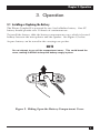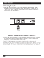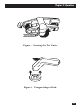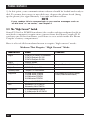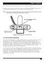
1
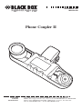
NOVEMBER 1996
MC155A-R2
Phone Coupler II
CUSTOMER
SUPPORT
INFORMATION
Order toll-free in the U.S.: Call 877-877-BBOX (outside U.S. call 724-746-5500)
FREE technical support 24 hours a day, 7 days a week: Call 724-746-5500 or fax 724-746-0746
Mailing address: Black Box Corporation, 1000 Park Drive, Lawrence, PA 15055-1018
Web site: www.blackbox.com • E-mail: [email protected]
FCC STATEMENTS
FEDERAL COMMUNICATIONS COMMISSION
AND
INDUSTRY CANADA
RADIO FREQUENCY INTERFERENCE STATEMENTS
This equipment generates, uses, and can radiate radio-frequency energy, and if not
installed and used properly, that is, in strict accordance with the manufacturer’s
instructions, may cause interference to radio communication. It has been tested
and found to comply with the limits for a Class A computing device in accordance
with the specifications in Subpart B of Part 15 of FCC rules, which are designed to
provide reasonable protection against such interference when the equipment is
operated in a commercial environment. Operation of this equipment in a
residential area is likely to cause interference, in which case the user at his own
expense will be required to take whatever measures may be necessary to correct
the interference.
Changes or modifications not expressly approved by the party responsible
for compliance could void the user’s authority to operate the equipment.
This digital apparatus does not exceed the Class A limits for radio noise emission from
digital apparatus set out in the Radio Interference Regulation of Industry Canada.
Le présent appareil numérique n’émet pas de bruits radioélectriques dépassant les limites
applicables aux appareils numériques de la classe A prescrites dans le Règlement sur le
brouillage radioélectrique publié par Industrie Canada.
1
PHONE COUPLER II
NORMAS OFICIALES MEXICANAS (NOM)
ELECTRICAL SAFETY STATEMENT
INSTRUCCIONES DE SEGURIDAD
1. Todas las instrucciones de seguridad y operación deberán ser leídas antes de
que el aparato eléctrico sea operado.
2. Las instrucciones de seguridad y operación deberán ser guardadas para
referencia futura.
3. Todas las advertencias en el aparato eléctrico y en sus instrucciones de
operación deben ser respetadas.
4. Todas las instrucciones de operación y uso deben ser seguidas.
5. El aparato eléctrico no deberá ser usado cerca del agua—por ejemplo, cerca
de la tina de baño, lavabo, sótano mojado o cerca de una alberca, etc..
6. El aparato eléctrico debe ser usado únicamente con carritos o pedestales que
sean recomendados por el fabricante.
7. El aparato eléctrico debe ser montado a la pared o al techo sólo como sea
recomendado por el fabricante.
8. Servicio—El usuario no debe intentar dar servicio al equipo eléctrico más allá
a lo descrito en las instrucciones de operación. Todo otro servicio deberá ser
referido a personal de servicio calificado.
9. El aparato eléctrico debe ser situado de tal manera que su posición no
interfiera su uso. La colocación del aparato eléctrico sobre una cama, sofá,
alfombra o superficie similar puede bloquea la ventilación, no se debe colocar
en libreros o gabinetes que impidan el flujo de aire por los orificios de
ventilación.
10. El equipo eléctrico deber ser situado fuera del alcance de fuentes de calor
como radiadores, registros de calor, estufas u otros aparatos (incluyendo
amplificadores) que producen calor.
11. El aparato eléctrico deberá ser connectado a una fuente de poder sólo del
tipo descrito en el instructivo de operación, o como se indique en el aparato.
2
NOM STATEMENTS
12. Precaución debe ser tomada de tal manera que la tierra fisica y la polarización
del equipo no sea eliminada.
13. Los cables de la fuente de poder deben ser guiados de tal manera que no
sean pisados ni pellizcados por objetos colocados sobre o contra ellos,
poniendo particular atención a los contactos y receptáculos donde salen del
aparato.
14. El equipo eléctrico debe ser limpiado únicamente de acuerdo a las
recomendaciones del fabricante.
15. En caso de existir, una antena externa deberá ser localizada lejos de las lineas
de energia.
16. El cable de corriente deberá ser desconectado del cuando el equipo no sea
usado por un largo periodo de tiempo.
17. Cuidado debe ser tomado de tal manera que objectos liquidos no sean
derramados sobre la cubierta u orificios de ventilación.
18. Servicio por personal calificado deberá ser provisto cuando:
A: El cable de poder o el contacto ha sido dañado; u
B: Objectos han caído o líquido ha sido derramado dentro del aparato; o
C: El aparato ha sido expuesto a la lluvia; o
D: El aparato parece no operar normalmente o muestra un cambio en su
desempeño; o
E: El aparato ha sido tirado o su cubierta ha sido dañada.
3
PHONE COUPLER II
TRADEMARKS USED IN THIS MANUAL
Apple is a registered trademark of Apple Computer, Inc.
Fujitsu is a registered trademark of Fujitsu Limited.
Gateway 2000 is a registered trademark of Gateway 2000, Inc.
Motorola is a registered trademark of Motorola.
AT&T and Merlin are registered trademarks of American Telephone and
Telegraph Company.
ProComm is a registered trademark of DATASTORM TECHNOLOGY INC.
Crosstalk is a registered trademark of Digital Communications Associates.
Any trademarks mentioned in this manual are acknowledged to be the property of the
trademark owners.
4
CONTENTS
Contents
Chapter
Page
1. Specifications..................................................................................................6
2. Introduction ..................................................................................................7
2.1 Overview................................................................................................7
2.2 What’s Included....................................................................................7
2.3 The Phone Coupler II ..........................................................................7
3. Operation ......................................................................................................9
3.1 Installing or Replacing the Battery......................................................9
3.2 Installing the Coupler ........................................................................10
3.3 The “High Current” Switch ................................................................12
3.4 Tips for Better Performance ..............................................................13
4. Manual Dialing and Modem Configuration................................................15
5. Troubleshooting ..........................................................................................17
5
PHONE COUPLER II
1. Specifications
Supported Telephone Types
Rotary or pushbutton with standard or
European handset; carbon granular or
electronic microphone
Operation
Full or half-duplex
Data/Fax Rate
Up to 14,400 bps using V.42 bis error
correction/data compression
Communication Line
Standard telephone lines (PSTN)
On/Off Switching
Automatic; power on only during
transmission
Connectors
(1) RJ-11 plug to connect to modem
Battery Life
50+ hours of continuous use
Temperature
Operating: 40 to 100°F (4.4 to 37.8°C);
Storage: 0 to 150°F (-17.8 to 65.6°C)
Power
9V battery; optional DC adapter for fixed
use
Size
7.7"H x 2"W x 2.2"D (19.6 x 5.1 x 5.6 cm)
Weight
0.6 lb. (0.3 kg)
6
Chapter 2: Introduction
2. Introduction
2.1 Overview
The Phone Coupler II is a high-speed acoustic coupler that connects your
modem to virtually any telephone. With it, you can send and receive faxes,
transmit data, check your email, or access on-line services from your portable
or notebook computer wherever you go.
Using advanced signal-processing technology, the Phone Coupler II can
interface with the telephone system when no direct connection is available.
Communicate over pay, cellular, hotel, digital/PBX, and international
telephones up to 14,400 bps. (The actual speed may vary, depending on the
telephone, modem, line conditions, and communications software.)
2.2 What’s Included
Your Phone Coupler II package should contain the following items. If any of
these items are missing, please contact your supplier.
• Phone Coupler II
• 9-volt alkaline battery
• This user’s manual
• Adapter disk (for square handset mouthpiece on AT&T® Merlin® phones)
2.3 The Phone Coupler II
The diagram on the next page (Figure 1) explains the various parts of the
Coupler. Refer to this diagram before attempting to use your Phone Coupler
II.
7
PHONE COUPLER II
Speaker: Place
against the
mouthpiece of
the telephone
handset.
Microphone: Place
against the earpiece of
the telephone handset.
Securing Band: Fastens unit
to the telephone handset.
RJ-11 Modular Plug:
Plug into the LINE jack
of the modem.
Figure 1. Parts of the Phone Coupler II.
8
Chapter 3: Operation
3. Operation
3.1 Installing or Replacing the Battery
The Phone Coupler II is powered by one 9-volt alkaline battery. One 9V
battery should provide over 50 hours of continuous use.
To install the battery, slide the battery-compartment cover, which is located
halfway between the microphone and the speaker. See Figure 2, below.
A spare battery can be stored in the carrying-case pocket.
NOTE
Do not attempt to pry off the compartment cover. This could break the
cover, making it difficult to keep the battery snugly in place.
Figure 2. Sliding Open the Battery-Compartment Cover.
9
PHONE COUPLER II
3.2 Installing the Coupler
1) Plug the Phone Coupler II into your computer’s modem jack. Some
modems have two jacks, labeled “LINE” and “PHONE”; always use the
“LINE” jack. (The “PHONE” jack is used to attach an analog phone to
make voice calls.) See Figure 3.
LINE
PHONE
Figure 3. Plugging Into the Computer’s LINE Jack.
2) Attach the Phone Coupler II to the telephone handset as shown in Figure
4. Strap the two units together tightly to provide a proper connection.
Make sure to note the position of the cords.
The AT&T Merlin phone system uses a handset with a chisel-shaped
mouthpiece. The Phone Coupler II includes a round rubber adapter that has
a notch on one side for the Merlin handset. The other side is placed over the
Phone Coupler II’s speaker to allow use of the Merlin handset. See Figure 5.
10
Chapter 3: Operation
Figure 4. Securing the Two Units.
Figure 5. Using an Adapter Disk.
11
PHONE COUPLER II
3) At this point, your communications software should be loaded and ready to
dial. To ensure that you get a new dial tone, depress the phone hook (hang
up the phone) for approximately 3 seconds and then release.
NOTE
If your modem fails to communicate or you receive messages such as
“no dial tone” or “no carrier,” see Chapter 4.
3.3 The “High Current” Switch
Some PC-Card or PCMCIA modems (the credit-card-size modems that fit in
notebook computers) require more current from the Phone Coupler II. If
you have one of those modems, you’ll have to set a switch inside the Phone
Coupler’s battery compartment.
Here is a list of all the modems known to require “high current” mode:
Modems That Require “High Current” Mode
Manufacturer
Model
Angia
PCMCIA 14.4 with V.32 connector
PCMCIA Safejack SJ-192
PCMCIA Safejack SJ-288
Apple®
Express Modem
AT&T Paradyne
All PCMCIA modems
Fujitsu
PCMCIA Safejack 28.8
Gateway 2000®
Telepath 14.4 fax/modem
Megahertz
CC3288 series PCMCIA
CC6288 series PCMCIA
XJ2288 series PCMCIA
XJ3288 series PCMCIA
Motorola®
Marquis 28.8 PCMCIA fax/LAN
NEC
Noteworthy 14.4 PCMCIA
Noteworthy 28.8 PCMCIA
New Media
V.34 Fax/Modem PCMCIA
V.34 Netsurfer 28.8 PCMCIA
Supra
28.8 fax/modem
®
12
Comments
Keep-in-Touch series
List includes all PCMCIA Combo
Cards (Ethernet/fax/modem)
Chapter 3: Operation
To find the switch, remove the battery cover and the battery.
For high-current mode, push the switch toward the small rubber cup (or the
slotted cup-mounting holes). See Figure 6 for an illustration.
NOTE: If the switch is set to the high-current mode, the battery life will be reduced from more
than 30 hours of modem use to about five or six hours.
“Standard”/“High Current”
Switch
Move to this side for
“Standard” mode
Move to this side for
“High Current” mode
Figure 6. Setting the current level.
3.4 Tips for Better Performance
Carbon-Granule Microphones—Many older phones, pay phones, and rotary dial
phones use an old style of microphone made of carbon granules. This
microphone can be identified by the round shape of the mouthpiece on the
telephone handset. Gently tap any phone handset with a carbon-granule
microphone against a hard surface to loosen the granules before connecting
the Phone Coupler II. If you’re unsure of the microphone type, tap the
handset anyway; this will not harm the phone.
Avoid Noise and Vibration—When possible, isolate the Phone Coupler II from
noise and vibration. (See the diagrams on the next page.) Quiet areas provide
for better communications. In general, if the phone you are using is not
suitable for a normal conversation because of external noise or poor line
conditions, use a different phone. Also, avoid placing the phone near your
keyboard or a printer.
13
PHONE COUPLER II
Phones with Volume Controls—Pay phones with volume controls are frequently
located in airports. If the volume control is set too loud, your modem can
become overloaded. Simply avoid using the switch on these pay phones to
avoid this problem. The volume control on any office phone should be set to
normal level.
High-Speed Modems—If line conditions will not support high data rates and
you’re having problems establishing a connection, force your modem to
connect at a slower rate, such as 2400 or 1200 bps. This is normally done
through your communications software
Error Correction—For the best performance, use modems with error-correction
features. They will remove occasional data errors caused by noise or poor line
conditions.
Flat surface—lying on side
Dangling
Figure 7. Positions to Keep the Phone Coupler II
Free From Noise and Vibration.
14
Chapter 4: Manual Dialing and Modem Configuration
4. Manual Dialing and Modem
Configuration
Cellular telephones and some pay, rotary-dial, international and digital or
PBX telephone systems will not accept the dialing tones produced by your
modem.
If your modem won’t dial automatically or you are using one of the phone
types listed above, simply follow the procedures below.
1. Look for a manual-dialing feature in your communications software.
When you select the manual-dialing feature, your software will lead you
through the dialing. Remember to get a new dial tone before dialing.
2. If your software doesn’t have a manual-dialing feature, you can still dial
for your modem; however, you must give the modem additional
information.
• Instruct your modem to ignore dial-tone detection. This feature will most
likely be found in your software’s modem-setup menu. Go to step 3.
• If your software doesn’t have an ignore dial-tone detection feature, you
must invoke the “ATX3” command, which will instruct the modem to
ignore the dial tone. Look for the box or command line labeled
“initialization string/command” or “dialing string/command.” Insert
“X3” immediately after “AT” in the command line. See Table 1 for
examples. Once you’ve entered the necessary initialization string or
command, save the configuration and restart your communications
software to make the changes take effect. Now you are ready to dial
manually.
15
PHONE COUPLER II
If your software has:
Then change the:
To:
A phone number to dial that includes
the characters ATD
A separate dialing prefix and phone
number or a dialing prefix that includes
the characters ATD
A field to enter a modem-initialization
string (and the characters AT do not
appear in any dialing field described
above)
phone number
ATX3DT1
dialing prefix
phone number
ATX3DT
1*
modeminitialization string
phone number
dialing prefix
add characters
X3 to the end
of the existing
modem-initialization string
1*
X3
phone number
phone number
1*
X3DT1
A separate dialing prefix (without ATD)
and phone number with no modeminitialization string
Only a phone number to dial with no
additional prefixes or strings
Only a phone number to dial with no
additional prefixes or strings and letter
characters are not accepted
If this is the only situation that
describes your software, call for
technical support.
* The phone number should be sent to the single digit “1.” This alerts the modem
to respond to an answer from the other modem.
3. Set up your communications software so that you need to press just one
more key for the modem to begin dialing.
4. Depress the hook switch (hang up the phone) for at least 3 seconds.
5. Release the hook switch and manually dial the phone number using the
telephone keypad. Remember to dial 9 for an outside line or 1 for longdistance if required.
6. Immediately after dialing, press the key that instructs your software to
begin dialing. This must be completed before the call is answered on the
other end. When the other modem answers, the two computers will
exchange the usual tones and establish a connection.
16
Chapter 5: Troubleshooting
5. Troubleshooting
Before proceeding, verify that your modem works properly when directly
connected to the phone line (without the Phone Coupler II). Then do the
following:
• Check for dead or weak battery by replacing the existing battery.
• Make sure the Phone Coupler II is correctly attached to the telephone
handset.
• Verify correct communications software setup.
• Minimize external noise and vibration.
If the Phone Coupler II still does not work, try the next suggestions.
1. By far, the most common connection failures are the result of improper
dialing. To determine if the problem is dialing-related, listen to your
modem speaker while dialing. If you can hear the telephone line ringing,
the other modem answering, and the tones from the other modem, then
you have dialed correctly. If not, you may receive messages on your screen
such as “no dial tone,” “busy,” “no carrier,” or “voice call detected.” These
messages indicate a dialing problem. Read Chapter 4 and follow the
procedures carefully.
2. If the other modem answers, but the modems fail to connect, likely causes
for the problem are:
• Poor Telephone Quality or Line Conditions—Use a different telephone
or lower modem speed.
• External Noise—Move to a less noisy location.
• Vibration—If possible, dangle the Phone Coupler II and handset by their
cords.
• Modem Incompatibility—Use a lower modem speed.
17
PHONE COUPLER II
3. If the Phone Coupler II is malfunctioning, the problem is either a transmit
or receive failure. To determine if the Phone Coupler II needs service, do
the following.
a) Using a terminal-emulator program (ProComm®, Crosstalk®, Terminal
accessory, etc.), type command “AT” and press the Enter key. The
modem should respond with “OK.” If it doesn’t, you have a
communications-software problem. Correct the problem before
proceeding.
b) Connect the Phone Coupler II to the telephone handset, get a fresh dial
tone, and type “ATM1L2X3DT 1234567890” and press Enter.
AT means “attention to the modem.”
M1 turns on the modem speaker.
L2 sets the modem speaker to medium loudness.
X3 tells the modem to dial without a dial tone.
DT means “dial using tones.”
1234567890 is a dummy phone number.
You should hear a dial tone from the modem speaker, followed by ten tones.
If you cannot hear a dial tone, then try another modem, preferably of a
different type. If the Phone Coupler II will not work with a different modem,
contact your dealer. Otherwise, see step c.
c) Remove the Phone Coupler II from the telephone handset. Hold the
Phone Coupler II speaker (the rubber cup nearest the line cord) 3 or 4
inches away from your ear. Type AT M0 X3 DT 1234567890 and press
the Enter key.
M0 (M zero) turns off the modem speaker.
If you can clearly hear the ten tones from the Phone Coupler II speaker, your
Coupler is functioning properly and the problem is either with your modem
or your software.
If the tones can’t be heard, repeat this step using another modem. If the
Phone Coupler II still won’t produce dialing tones, call Black Box.
18
© Copyright 1996. Black Box Corporation. All rights reserved.
1000 Park Drive
•
Lawrence, PA 15055-1018
•
724-746-5500
•
Fax 724-746-0746