1
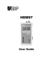
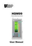
HDM97
Dialysis Measuring System
User Manual
Attention
Read these safety instructions before using the HDM97
•
Please read the manual before using the HDM97.
•
Keep away the device from unauthorized persons.
•
Never use the HDM97 with connected battery charger
on a dialysis machine to which a patient is connected.
•
Operate the instrument only in a dry environment, and
do not touch it with damp hands. Ensure that no fluids
intrude into the interior of the device or into the sockets
at the front.
•
Apply a protection filter to the nozzle for the pressure
measurement .
•
Avoid a discharge of static electricity over the sockets.
It could lead to the destruction of your measuring
device. Before touching the sockets and lines that are
connected with them, keep an eye on the discharging of
static electricity.
•
Only calibrate the device if you have understood the
consequences to their full extent.
•
Do not open the device.
The information contained in this documentation can undergo changes
without special announcement. IBP Instruments GmbH takes no
responsibility with this document. The contained software is being
delivered on the basis of a general licence contract or in single license. Use
or reproduction of the software is allowed only in agreement with the
contractual arrangements. Whoever transfers this software and/or this
manual on magnetic tape, diskette or any other media, except for the
purpose of own use, without written authorization of the IBP Instruments
GmbH, is liable to prosecution.
Copyright (C) 1997, IBP Instruments GmbH.
All rights reserved
Publishers:
IBP Instruments GmbH
Sutelstr. 7a
D 30659 Hannover
Germany
http://www.ibpmt.com
IBP Instruments Inc
635 South Orange Avenue
Sarasota, FL 34236
Manual author:
Horst Müller
3rd Edition April 2000 Version 2.0
Delivery extent................................................................................................... 6
EC-Conformity Declaration ................................................................................ 7
Software Service................................................................................................. 8
Guarantee directives ........................................................................................... 8
About this manual............................................................................................... 9
Introduction...................................................................................................... 10
Connections...................................................................................................... 11
Conductivity / Temperature........................................................................... 11
Pressure........................................................................................................ 11
pH ................................................................................................................ 12
Charge connection ........................................................................................ 12
Switching on the unit........................................................................................ 14
Main Menu....................................................................................................... 14
Measurement.................................................................................................... 16
Temperature measurement ................................................................................ 16
Conductivity measurement................................................................................ 16
Selecting a temperature coefficient.................................................................... 19
Pressure measurement....................................................................................... 20
pH measurement........................................................................................... 22
Charging state, battery .................................................................................. 24
Calibrating of the unit ....................................................................................... 25
Calibration.................................................................................................... 25
Maintenance and care of the HDM97 ................................................................ 31
Storage ......................................................................................................... 31
Cleaning ....................................................................................................... 32
Calibration intervals...................................................................................... 33
Specifications for the HDM97........................................................................... 35
RS-232-Interface............................................................................................... 36
HDM97 Commands.......................................................................................... 37
Activate Communication: ...................................................................... 37
Deactivate Communication: .................................................................. 37
New Device-Number: ............................................................................. 38
Conductivity Measuring Range: ........................................................... 38
Deactivate Conductivity Measuring Range: ...................................... 38
Give out Units: ......................................................................................... 39
Give out values: ....................................................................................... 39
Functional messages ......................................................................................... 40
Error messages.............................................................................................. 40
Index ................................................................................................................ 41
6
Introduction
Delivery extent
The hardware of HDM97 consists of:
HDM97 plus
Combined electrode conductivity / temperature
Flow-through connector for conductivity/temperature probe
Pressure measuring tube
Battery charger
Standard solution conductivity 13,63 mS/cm
The documentation of HDM97 consists of this manual.
If you should miss anything, please contact your supplier.
Introduction
7
EC-Conformity Declaration
Hereby we declare that the HDM97 corresponds to the basic requirements
for protection according to the guidelines of the board for the assimilation
of legal regulations about electro-magnetic compatibility (89/336/EWG) of
the member states.
For the rating of the devices in view to their electro-magnetic compatibility
the following norms have been used:
Emission:
Immission:
EN 55022 Class B
IEC 801-3 Criterion A
IEC 801-2 Criterion A
IEC 801-4 Criterion B
This declaration is responsibly given for
IBP Instruments GmbH
Sutelstr. 7a
D-30659 Hannover, Germany
http://www.ibpmt.com
by
Dipl. Ing. Werner Pfingstmann
Managing director
Hannover, June 10, 1997
8
Introduction
Software Service
Your first contact should always be your specialist supplier where your
device was purchased. He should be able to help you especially in the early
stages, in case any problems arise which you are unable to solve by
yourself.
Guarantee directives
The existing product is a technical device which contains only modern
electronic components. During the manufacturing exclusively first choice
parts are used. Each device undergoes extensive tests before delivery.
IBP warrants that the device is free from defects in material and
workmanship for a period of 12 months beginning at the date of delivery.
Excluded from the guarantee are damages by improper treatment,
inappropriate usage, by connecting to excess voltages, modifications in the
device or through risks which the user has to cover by a suitable insurance
(fire, water, intrusion, robbery etc.)
All conceivable measures were met to assure the accuracy of this productdocumentation. IBP cannot grant any guarantee for the completeness and
the accuracy of the software and the documentation. IBP is not responsible
for damages (including, but not limited to, damages for loss of business
profits, business interruption, loss of data, and other special, incidental or
consequential damages) which emerge through the usage of the product by
the customer.
Introduction
9
About this manual
Documentations about technical products are always a difficult matter.
Actually, manuals like this should not be written by a technician, but in the
diction of the future user. As a rule, unfortunately, the eloquent layman is
missing the background knowledge to describe technical relations correctly.
Therefore, in our house, manuals are still written by technicians. We hope
indeed that we have been successful in composing a well readable text
which at the same time does not leave open any technical questions.
10
Introduction
Introduction
HDM97 is an innovative computer processed measuring system with which
nine parameters can be measured:
Conductivity
Temperature
Pressure
pH
The device has been developed for the usage on dialysis machines, but is
also usable in the labor in the environmental measuring technology.
The handling is uncomplicated and follows the motto: Only the manual is
necessary in cases of doubt.
The measured values are displayed numerically.
They can be called up independently of the current display via the serial
interface and can be shown or further processed on, for example, a PC.
Introduction
11
Connections
Conductivity / Temperature
The conductivity measurement is designed for quadropole technology.
Please use exclusively the electrode delivered with the device by IBP.
Pressure
To avoid damages at the pressure probe or inaccuracies in measurement,
ensure that no fluids intrude into the device.
We recommend the application of a protection filter.
12
Introduction
pH
The input bushes are intended exclusively for pH-electrodes. Other signals
may destroy the device.
Charge connection
The charge connection is found at the right side of the device. The
connection is provided with 12 V / 500 mA by the included battery charger.
For safety reasons never use the HDM97 with connected
battery charger on a dialysis machine to which a patient is
connected.
Introduction
13
Combined electrode in Hansen-connector
In the flow-through mode the connector is
suitable
for
measuring
pressure,
temperature and conductivity. In the dip-in
mode temperature and conductivity can be
measured. The preferential position of the
Hansen-connector is vertical, the axial
supply shows downward.
In the flow-through mode the axial supply
is used as input and the radial supply as
output (see illustration). The pressure
probe in HDM97 is fastened to the radial
connection above the input. Before any
measurements you must shake the
connector to assure that any air within the
system escapes.
For the dip-in mode open the screw cap at
the upper end of the connector and
extract the combined electrode. You must
not remove the tube covering the probe
carrier. Dip the electrode into the media
up to a level above the borings in the
covering tube. By moving the electrode
you assure that the contained air can
escape and the temperature is well
balanced.
Do not touch the surface of the electrode with your
fingers.
14
Introduction
Switching on the unit
The unit is switched on and off via the keys I and O.
The unit also switches itself off automatically when the battery is flat.
Main Menu
After switching it on, the device automatically enters the conductivity
measuring mode.
By pressing the function keys shown, the required measurement channel
will be activated and acknowledged by an acoustic confirmation. The
measuring mode selected will be indicated by the relevant LED flashing.
The key for the conductivity measuring mode has two functions. If the
conductivity channel is active, pressing this key will change over to the
temperature coefficient setting mode. This mode will be indicated by both
the conductivity key LEDs flashing.
Introduction
15
The keys shown below are used for calibrating conductivity and pH
measurement, for balancing pressure measurement, for setting the
temperature coefficient, and also for accepting default values.
The Kal key, which shows a calibration curve symbol, will call up or
complete the calibration and balancing processes and also the process for
accepting default values, and will accept relevant values. The LED
integrated into the Kal key indicates the respective process from call-up to
completion by flashing.
Using the arrow keys in the calibration mode, the reference solution value
for conductivity measurement and the buffer solution value for the pH
measurement are changed. Pressing these during the temperature
coefficient setting process will select different dialysis machine
manufacturers’ temperature coefficients. In case the device is in none of the
above setting modes, pressing one of the two arrow keys will bring up the
HDM97’s software version.
Adjustment Key
Up Arrow Key
Down Arrow Key
In case the device is in none of the above setting modes, pressing one of the two
arrow keys will bring up the HDM97’s software version.
16
Measurement
Measurement
Temperature measurement
Pressing function key °C will call up the temperature measuring mode. The
temperature value measured will be shown on the display with one digit
after the decimal point.
The temperature sensor is suitable for a temperature range from 0 °C to 100
°C. In case this temperature range is not observed, a range message OFL
will appear on the display, indicating that the measuring range has been
exceeded.
In case error message E11 is shown on the display instead of the
temperature value, and an acoustic signal sounds simultaneously, no
temperature sensor was found. One reason for this error message is the
temperature sensor being defective or incorrectly installed.
Conductivity measurement
By pressing function key mS/µS, you will enter the conductivity measuring
mode. The current temperature coefficient will briefly be indicated. Then
the conductivity value is shown on the display, depending on the relevant
conductivity measuring range, with a maximum of two digits after the
decimal point. The conductivity electrode is suitable for measuring
conductivity values within a range of 0 – 19.99 mS/cm, which is divided
into four conductivity measuring ranges to provide highly accurate
measurements.
The internal pressure sensor is suitable for a pressure measuring range of 750 to +750 mmHg, or -100 to +100 kPa. If the measuring range is not
observed, a range message OFL, indicating that the measuring range has
been exceeded, appears on the display. Depending on the drift of the
pressure sensor, the pressure display can vary slightly in the zero point. The
balancing function sets the display to zero. However, pressure must not be
applied to the sensor in this case. This is reliably achieved achieved
Measurement
17
Conductivity Measuring Range
In case a range message OFL is shown on the display, this indicates that the
measuring range has been exceeded.
The conductivity measuring ranges are switched automatically. The LEDs
integrated into function key mS/µS
I : 0 - 19,9 µS/cm
show the unit used in measuring the
II : 0 - 199 µS/cm
conductivity value, e.g. mS/cm or
III : 0 - 1,99 mS/cm
µS/cm.
IV : 0 - 19,9 mS/cm
A temperature compensation of the
conductivity value measured is carried out automatically by the temperature
sensor integrated into the conductivity electrode, within a temperature
range of 0 °C to 100 °C, with an adjustable temperature coefficient of 0 .. 4
% per °C. Reference temperature is 25 °C.
Temperature coefficients
Temperature coefficients with conductivity measurement:
Important – frequently misunderstood and often neglected
A solution’s conductivity will change according to temperature. With
increasing temperatures, the measured solution’s conductivity will increase,
too. To achieve meaningful measuring results, the value displayed is
compensated to 25 °C. In other words, the display is always converted to a
solution temperature of 25 °C. The temperature coefficient which the
displayed value is compensated with is expressed as %/°C. Unfortunately
however, different solutions also have different temperature coefficients.
To achieve an exact display, the measuring device will have to be adjusted
to the temperature coefficient of the current solution. The average
temperature coefficient for dialysates is 2.07 %/°C.
For naturally occurring solutions, a value of 1.97 %/°C is frequently used.
Many measuring devices not specially tailored to dialysis will use this
value. The calculation below shows the drastic effects of an incorrect
temperature coefficient.
18
Measurement
To create perfect chaos, different dialysis machine manufacturers will also
use different temperature coefficients in their machines.
Baxter 2,20%/°C
Braun 2,00%/°C
FMC 2,10%/°C
Gambro 1,80%/°C
Hospal 2,07%/°C
Mesys Miro1 2,00%/°C
Nikkiso
Bicarbonat 2,02%/°C
Gesamtleitfähigkeit 2,05%/°C
Example calculation for an incorrect temperature coefficient, using a
dialysate with a temperature coefficient of 2.07 %/°C.
This necessarily leads to the following conclusion:
Set your measuring device for each measurement to the temperature
coefficient the dialysis machine uses for compensation.
Setting the temperature coefficient
The HDM97 enables you to easily set different temperature coefficients.
You can choose between eight fixed settings and a variable value. The
fixed values are values of frequently used dialysis machines. The variable
value can be set to any required value.
Measurement
19
Selecting a temperature coefficient
If the HDM97 is in the conductivity measuring mode, pressing the
conductivity function key once again will change over to the temperature
coefficient setting mode.
Changing to this mode will be initiated briefly by displaying 'tC'. Both the
conductivity function key LEDs will flash. The temperature coefficient
currently set will be displayed for ca. five seconds. In case no other key is
pressed during this time, the HDM97 will automatically return to the
conductivity measuring mode.
In case any of the two arrow keys is pressed within these five seconds, each
time the key is pressed, the pre-set temperature coefficients will be
displayed one after the other. By pressing the KAL key, the selected value
can be accepted for further conductivity measurements.
The value set for the temperature coefficient by the user will be displayed
twice when using the selection procedure above. When this value is
displayed for the second time, a short acoustic signal sounds, and the KAL
key LED will also flash. After pressing the KAL key, the variable
temperature coefficient may be changed to any value within a range of 0.00
to 4.00 %/K. By pressing the KAL key once more, the set value is
accepted. All settings will be saved permanently and are still present even
after switching the HDM97 off.
It is possible to cancel the temperature coefficient setting mode at any point
described above by pressing the channel selector keys. Any values possibly
changed will not then be saved.
20
Measurement
Pressure measurement
By pressing the function key mmHg/kPa, you will enter the pressure
measuring mode. The pressure value measured is displayed with no digits
after the decimal point for pressure unit mmHg, and with one digit after the
decimal point for pressure unit kPa.
The internal pressure sensor is suitable for a pressure measuring range of 750 to +1600 mmHg, or -100 to +199.9 kPa. In case the measuring range is
not observed, a range message OFL appears on the display, indicating that
the measuring range has been exceeded.
Depending on the drift of the pressure sensor, the pressure display may
vary slightly in the zero point. The display can be set to zero using the
balancing function. However, pressure must not be applied to the sensor
when doing so. This can be safely achieved by leaving the pressure
measurement connection point unoccupied. The zero point for balancing
purposes will then be the ambient pressure.
Unit
In the pressure measurement, repeated pressing of the function key also
enables the unit to be changed as required between mmHg and kPa. The
values are converted if the unit is changed. Recalibration is not necessary.
Balancing an offset
Balancing must be carried out as follows
Press the function key mmHg/kPa and hold it down, then press the Cal key.
The display is then counted backwards from 5 to 0. Keep the Cal key
pressed until an audible check-back message is issued and a zero appears in
the display.
If the Cal key is pressed for longer, there is a possibilitiy of standard values
being accepted. Read the section Standard Values for details.
If the Cal key is released prematurely, the balancing is ended without
relevant values being accepted. The error message E22 appears in the
display. The unit is now in Balancing mode, which is indicated by the LCD
integrated in the Cal key flashing. If the displayed pressure measurement
value has reached a stable state, balancing is performed by keeping the Cal
Measurement
21
key pressed until an audible check-back signal is issued and until a zero
appears in the display. The display is counted backwards from 5 to 0. If the
Cal key is released prematurely, the error message E33 appears. You now
have the possibility of continuing the balancing the operation. If the Cal
key is again released prematurely, the error message E44 appears. No
balancing takes place. The unit then exits Balancing mode and returns to
the pressure measurement.
Completed balancing is acknowledged in the display with CAL. The unit
then exits Balancing mode and returns to the pressure measurement.
22
Measurement
pH measurement
Pressing the function key pH takes you into the pH value measurement
mode. The measured pH is displayed with two decimal places. The
combined electrode used for the pH value measurement is suitable for a
measurement range of 0 to 14. If the measurement range is not observed,
the range message OFL, signaling that the measurement range has been
exceeded, appears in the display. If error message E11 appears in the
display instead of the pH value and if an audible signal sounds at the same
time, no combined electrode has been recognized. The reason for this error
message can be an incorrectly inserted or faulty combined electrode.
Temperature compensation, pH measurement
For automatic compensation of the pH measurement, the unit offers the
possibility of measuring the solution temperature via the temperature
sensor. If no temperature sensor is connected, a solution temperature of 20
°C is assumed.
Fundamental information about pH-measurement
For the measurement of the pH-value a combined electrode is used. pH
electrodes are combinations of one reference electrode and one measuring
electrode in a glass tube.
The pH-value in the dialysate is measured by an unbreakable pH-electrode.
The glass body is protected with a plastic coat and due to the jellyelectrolyte-filling maintenance-free. This electrode` s diaphragm must be
stored in 3 mol/l KCl-solution. The protection hood must be refilled every
three to four weeks.
Measurement
23
For pH-measurement in untreated desalinated water a particular electrode is
necessary. This glass electrode is optionally available and has a 1 mol/l KCl
reference electrolyte. The diaphragm of this electrode must be stored in
1 mol/l KCl-solution.
Before usage the electrode must be checked on exterior damage and glass
crash. Crusts caused by leaking electrolyte can be removed easily by
rinsing. The sample volume should be 100 ml dialysate or 1 l of untreated
water. The sample volume is being led to the bottom of the vessel with a
tube or hose for coming as little as possible into contact with air. The pHvalue must be measured immediately in the same vessel. You have to make
sure that the display stabilizes before the value is read. In stirred solutions
the response rate is faster, the value, however, must be measured at resting
fluid.
The pH-electrode must be dabbed only and never rubbed dry. The rubbing
destroys the jelly layer on the glass surface which results in a longer
response time of the electrode.
Due to the special electrode, for pH-measurement in untreated water further
points need to be paid attention to: air bubbles in the membrane space of
the electrode can be removed easily by shaking movements similar to a
clinical thermometer. The reference electrolyte in this electrode can be
refilled. Make sure that the refill cap is sealed with the rubber hood.
The level of the reference electrolyte must always be sufficiently large.
Before the measurement the rubber hood must be removed, since otherwise
no internal pressure compensation occurs. On the lower shaft of the
electrode a plastic part is to be found which must always remain freely
movable on the shaft. If the mobility of the plastic part should be restricted
it can be released by rinsing with lukewarm water. This plastic part
conceals an opening in the glass which must be covered always. Pressure
and currents have considerable influence on the pH-measurements.
Therefore, it is necessary to accomplish the pH-measurement in a resting
solution at environmental pressure.
24
Measurement
Charging state, battery
The battery must be charged if LOW BAT appears in display at the top left.
The processer-controlled charging occurs when the power supply unit is
connected. There are two charging modes: Rapid charging and floating
charging. The LCDs above the key I indicate this state. Green stands for
floating charging, while the red LCD indicates rapid charging.A maximum
of 2.5 hours are required for complete charging.
For safety reasons, never operate the measuring unit with
a charging unit connected to a dialysis machine to which
a patient is also connected.
Calibration
25
Calibrating of the unit
Calibration
Calibration of the individual channels is slightly different.
The pH measurement is calibrated at 2 points.
The conductivity is calibrated by measuring the cell constant. Only one
calibration point is necessary for this.
The temperature and pressure measurements are calibrated exclusively via
the program HDMCal, in conjunction with the PC.
If at any point during the program sequence, during calibration of pH
measurement or during the calibration of the conductivity on the unit, you
are unsure whether you have correctly entered all values, you can exit the
calibration procedure in a targeted way. After you have done so, no
calibration is performed and you can start again from the beginning. The
necessary steps for exiting the relevant calibration procedure are described
in detail in the Calibration, pH measurement and Calibration, Conductivity
Measurement sections.
If a calibration is incorrect, you have the possibility of accepting the
standard values for every measurement mode. Refer to the Standard Values
section for details.
Calibration, temperature measurement
The temperature measurement is calibrated exclusively via the program
HDMCal in conjunction with a PC.
26
Calibration
Calibration, conductivity measurement
In order to avoid incorrect measurements which can occur as a result of
deposits on the electrode after extended use and which can influence the
cell constant, it is necessary to calibrate the conductivity measurement.
However, before doing so you must ensure that the temperature is
calibrated. In the event of heavy contamination of the electrode, cleaning
with a 10% citric acid solution is recommended.
We recommend that you check the calibration once each month.
Perform calibration as follows
Press the function key mS//µS and keep it pressed, then press the Cal key.
The display is counted backwards from 5 to 0. Keep the Cal key pressed
until an audible check-back signal is issued and zero appears in the display.
If the Cal key is kept pressed for longer, it is possible for
the standard values to be accepted. Refer to the section
Standard Values for information.
If the Cal key is released prematurely, the calibration is terminated without
relevant values being accepted. The error message E22 appears in the
display.
The unit is now in calibration mode, and this is indicated by the LCD
integrated in the Cal key flashing. 13.63 mS/cm appears as a reference
solution value in the display. This can be changed with the arrow keys in a
range 10 to 15 mS/cm, depending on the reference solution being used.
Calibration should be performed for measurements in dialysis in a range of
13...14 mS/cm and the reference solution should have a temperature of
exactly 25 °C (± 0.1 °C).
Pressing the function key mS/µS allows the display value to be changed
between the reference solution and the measured conductivity value. The
temperature of the reference solution can be displayed by pressing the
function key °C.
If the displayed conductivity measurement value has reached a stable state,
keeping the Cal key pressed performs the calibration until an audible
check-back signal is issued and a zero appears in the display. The display is
counted backwards from 5 to 0 in this case. If the Cal key is released
prematurely, the error message E33 appears. You now have the possibility
Calibration
27
of continuing the calibration. If the Cal key is again released prematurely,
the error message E44 appears. No calibration is performed. The unit then
exits Calibration mode and returns to the conductivity measurement.
Completed calibration is acknowledged in the display with CAL and the
cell constant determined is then displayed for approximately 2 seconds. The
unit then exits Calibration mode and returns to the conductivity
measurement.
If a calibration is not ended with the display CAL, with the error message
E66 appearing instead, no permissible cell constant was determined. The
cause can be, for example, an incorrectly set value for the reference
solution. You then have the possibility of continuing the calibration
procedure or exiting it in accordance with the diagram shown.
When calibrating the conductivity, work only with fresh
reference solutions. Do not return used solutions to the
storage bottle. Keep the solutions in a cool place.
.
28
Calibration
Calibration, pressure measurement
Calibration of the pressure measurement is performed exclusively via the
program HDMCal in conjunction with a PC.
Calibration, pH measurement
We recommend inspection of the calibration before each measurement.
Keep two buffer solutions ready. Both buffers should not be more than two
activity decades apart. Choose, for example, pH6 and pH8. Carefully
remove the protective cap before performing the measurement. Rinse the
measuring chain with distilled water and dab it dry before immersing it into
the buffer. If necessary, also rinse the temperature sensor, dry it and put it
into the measuring beaker.
Please also read the fundamentals
in the pH measurement section.
Temperature compensation pH measurement
For automatic temperature compensation for the pH measurement, the unit
offers the possibility of measuring the solution temperature via the
temperature sensor of the conductivity electrode. If no temperature sensor
is connected, a buffer solution temperature of 20 °C is assumed.
Perform the calibration as follows
Press the function key pH and then keep the Cal key pressed. The display is
counted backwards from 5 to 0. Keep the Cal key pressed until an audible
check-back signal is issued and zero appears in the display.
If the Cal key is kept pressed for longer, there is a risk of
the standard values being accepted. For details read the
section Standard Values.
Calibration
29
If the Cal key is released prematurely, the calibration is ended without
relevant values being accepted. The error message E22 appears in the
display.
The unit is now in Calibration mode, indicated by the LCD in the Cal key
flashing. The pH value 7 appears in the display. This can be changed to the
buffer solution being used with the arrow keys in a range of 1-14 in unit
steps.
Pressing the function key pH enables the display value to be changed
between the set buffer solution and the measured pH value. The buffer
solution temperature can be displayed by pressing the function key °C.
If the displayed pH value has reached a stable state, calibration is
performed by keeping the Cal key pressed until an audible check-back
signal is issued and a zero appears in the display. The display is counted
backwards from 5 to 0. If the Cal key is released prematurely, the error
message E33 appears. You now have the possibility of continuing the
calibration. If the Cal key is again released prematurely, the error message
E44 appears. No calibration is performed. The unit then exits Calibration
mode and returns to pH measurement.
Acceptance of the values is acknowledged in the display with P1. The
combined electrode is then immersed into the second buffer solution. The
further procedure is identical to the one described above. Completed
calibration is acknowledged in the display with CAL and the gradient
measured is then displayed in % for approximately 2 seconds. If the
gradient is less than 85%, the combined electrode may be worn out and
must be replaced by a new one. The unit then exits Calibration mode and
returns to pH measurement.
If a calibration is not ended with the display CAL and if the error message
E77 appears instead, 2 identical values have been entered for the buffer
solution. You then have the possibility of continuing or exiting the
calibration procedure in accordance with the diagram shown.
30
Calibration
Standard Values
If a calibration is incorrect, you have the possibility of separately accepting
the standard values for each measurement type installed in the unit during
production.
Use this function only if you are fully aware of its effects,
because your calibration values will otherwise be lost.
Accept the standard values as follows.
Press the function key of the measurement type whose calibration values
are to be replaced by the standard values and then keep the Cal pressed.
The display is counted backwards from 5 to 0. If the Cal key is released
prematurely, the error message E22 is displayed. The unit returns to the
previously set measurement type. Counting backwards from 50 to 0 in
increments of 10 then occurs. Keep the Cal key pressed until an audible
check-back signal is issued and a zero appears in the display after the
backward-counting in increments of 10. If the Cal key is released
prematurely in this counting mode, you are in Calibration or Balancing
mode, depending on the measurement selected. You can exit this mode by
pressing the CAL key. If you do this, the display is counted backwards
from 5 to 0. If the Cal key is released before zero is reached, the error
message E33 appears. If the Cal key is then pressed again and prematurely
released before reaching zero, the error message E44 appears. The standard
values are not accepted. The unit exits Calibration or Balancing mode and
returns to the previously set measurement mode.
If you are in the Temperature measurement mode, the outlined steps for
exiting the mode are not necessary. Merely the error message E55 is
displayed. The unit then returns to Temperature measurement.
Acceptance of the standard values is acknowledged in the display with
CAL. The accepted standard values are valid immediately. The unit then
leaves Acceptance mode and returns to the previously set measurement
mode.
Maintenance
31
Maintenance and care of the HDM97
Generally the HDM97 can be considered as an easy-care instrument. Like
at all measuring instruments there is a minimum of maintenance and care
necessary to ensure that all functions work flawlessly.
For safety reasons never use the HDM97 with connected
battery charger on a dialysis machine to which a patient is
connected.
Operate the instrument only in a dry environment, and do not touch it with
damp hands. Ensure that no fluids intrude into the interior of the device, or
into the sockets at the front. If this ever happens, open the device and
remove the batteries. Sink the whole device into a vessel with distilled
water over night. Afterwards, dry the HDM97, and send it to the producer
for repair.
There are no parts in the HDM97 which you can repair yourself. Please,
turn to our technical support at evident malfunctions that can not be
removed by a new calibration of the device,. If the device should show any
damages, or malfunctions by moisture influence, send it to the producer for
repair.
Storage
Keep the device at a dry place. Suitable is, for example, the original
packaging in which you have received the HDM97, or the carrying case
offered by IBP as accessory. If you do not use the device over a longer
period of time, you should connect it to the included charging device about
every two weeks for one hour to avoid exhaustion of the installed batteries.
32
Maintenance
Cleaning
Never clean the device with any fluids! In case of pollution you can wipe
the surface of the HDM97 with a dry and clean cloth.
For measurements in the lower conductivity range the cleaning of the
conductivity / temperature measuring cell is recommended. Remove watersoluble substances by rinsing with de-ionized water, fats and oils with
warm water and household dish washing detergent. Lime and hydroxid
crusts can be solved by 10 per cent acetic acid. In each case, the measuring
cell needs to be washed with de-ionized water after the cleaning.
Basically, the conductivity measuring cell does not decay. Particular
measuring media (for example, strong acids and caustic solutions, organic
solvents), or too high temperatures shorten the service life considerably,
and/or lead to damages.
Caring for the conductivity / temperature electrode
Thorough cleaning of the electrode is particularly important for measuring
low conductivities.
Water-soluble substances must be removed by rinsing with deionized
water. Remove lime desposits with a 10% solution of acetic acid. To do
this, immerse the electrode in the solution for 24 hours, then rinse it
thoroughly with deioinzed water. Do not touch the electrode surface with
your fingers. If necessary, clean the surface with acetone.
Maintenance
33
Calibration intervals
In the delivery state each device is newly adjusted. To assure a reliable
function of the HDM97, the different measuring channels have to be
calibrated at fixed intervals to examine their precision. This can be done by
measuring known sizes, for instance, standard solutions, or proof voltages.
If the measured values should deviate from the below indicated permissible
limits, a new calibration of the instrument is necessary. We recommend the
following intervals for the examination:
pressure measurement:
conductivity measurement:
temperature measurement:
pH measurement:
once a year,
once a month,
once a year,
before each measurement.
If for individual measuring channels the function adjust reset was used,
then a new calibration is necessary for these channels.
To handle the calibration, please read the individual sections in which the
calibration is described for the different channels.
Write down your calibration values and keep them until
the next calibration. In case of damage, a calibration
protocol can be important for the fault location.
If the calibration has been done by the IBP, a sticker will
be put on showing the date of the next calibration
necessary.
For liability reasons you should not carry out the
calibration yourself. If IBP has been charged with the
calibration, you will receive a calibration certificate which
documents the calibration results.
34
Maintenance
Allowed limits
measuring channel
measuring range
allowed limits
pressure
-700...+1600 mmHg
± 2 mmHg
-100 + 199.,9kPa
± 0,3 kPa
conductivity
0...19,99 mS/cm
± 0,03 mS/cm
temperature
0...80 °C
± 0,1 °C
80...100 °C
± 0,2 °C
pH 0 ... pH 14
± 0,1 pH
pH
Specifications
35
Specifications for the HDM97
Conductivity
0...19,99 mS/cm in 4 ranges, quadro-pole-electrode, temperature
compensation with 2,07 % per °C, temperature sensor integrated in the
measuring cell, reference temperature 25°C,
precision better than 0,25 % of full measuring range
Temperature range, adjustable from 0.00% to 4.00% per °C
Temperature
0...100°C, resolution 0,1 °C,
precision better than ± 0,1°C
probe integrated in combined conductivity / temperature electrode
Pressure measurement
-700...+1600 mmHg, precision better than 0,5 % of full measuring range,
connection over tube nozzles
pH-measurement
Electrode is not included in the delivery extent, pH 0...14, resolution 0,01,
precision better than 0,2 pH, temperature range 0...60 °C, temperature
calibration manually or via probe in combined electrode.
Power supply
Battery rechargeable with 12 V, 450 mA DC,
Operating time, depending on operating mode, approx. 19.5 hours
Size
approx. 210 x 105 x 50 mm
36
Additional
RS-232-Interface
Pin occupation of the RS-232-interface
Pin No. Signal
HDM97
Pin No. Signal
computer
2
3
5
3
2
5
RxD >
TxD >
GND >
TDX
RXD
GND
Interface parameters
The following interface parameters are fixedly adjusted at the HDM97
Baud rate
Parity
Data bits
Stop bit
9600
None
8
1
Additional
37
HDM97 Commands
General:
1 .All values like : <12.34>
2. Device-Number: xx
3. Conductivity range: y
4. Inadmissible commands call forth ‘ERROR’
5. 9999.99 > no Sensor
Activate Communication:
Host : HDM97xxSTA<cr>
HDM: OK<cr><lf>
Deactivate Communication:
Host: HDM97xxSTO<cr>
HDM: OK<cr><lf>
38
Additional
New Device-Number:
Host : HDM97xxDxx<cr>
Device-Nummer nur von 1 ..32
HDM: OK<cr><lf> oder ERROR<cr><lf>
OK > Device-Nummer wird übernommen.
ERROR > Device-Nummer wird nicht übernommen.
Conductivity Measuring Range:
Host: HDM97xxLFy<cr>
y=
1 > 0 - 20 µS
2 > 0 - 200 µS
3 > 0 - 2 mS
4 > 0 - 20 mS
HDM: OK<cr><lf> oder ERROR<cr><lf>
OK > Bereich zulässig
ERROR > Bereich unzulässig
Deactivate Conductivity Measuring Range:
Host: HDM97xxLFN>
HDM: OK<cr><lf>
Additional
Give out Units:
Host: HDM97xxUNI<cr>
HDM: <µS oder mS><cr><lf>
<°C><cr><lf>
<kPa><cr><lf>
Give out values:
Host: HDM97xxVAL<cr>
HDM: <Leitfähigkeitswert><cr><lf> [ mS/µS ]
<LF-Strom (indirekt )><cr><lf> [ mV ]
<LF-Spannung><cr><lf> [ mV ]
<Temperatur><cr><lf> [ °C ]
<Temperatur - ADC><cr><lf> [ mV ]
<Druck><cr><lf> [ kPa ]
<Druck - ADC><cr><lf> [ mV ]
<PH><cr><lf>
<PH - ADC><cr><lf> [ mV ]
39
40
Additional
Functional messages
Error messages
During calibration or measurement, a double audible signal and a message
in the LCD display indicate faults to the user.
E11
E22
E33
E44
E55
E66
E77
E88
No sensor recognized
Calibration call-up not permissible
Calibration error (first warning)
Calibration error (calibration is ended)
Temperature calibration not possible
Cell constant cannot be identified
Identical buffer solutions
Measurement in the selected measurement
mode not possible due to invalid calibration
values.
In order to be able to commence measurement
operation, you have the
possibility
of
accepting the standard values or performing
recalibration.
Range message
OFL Measurement range exceeded
Calibration message
CAL Calibration values safeguarded
P1
first pH values accepted
Additional
Index
Calibration 33
Calibration intervals 33
care 31
charging device 12, 31
Charging device 6
Cleaning 32
Combined electrode 6, 13
Conductivity 10, 11, 35
Connections 11
dialysate 22, 23
dialysis machines 10
Guarantee 8
hansen-connector 13
HDM97 Befehle 37
Interface parameters 36
Maintenance 31
Permissible limits 34
pH 12, 22, 23, 33, 34, 35
Pressure 6, 10, 11, 23, 35
RS232 Interface 36
safety 2, 12, 31
software 3, 8
Specifications 35
Standard solution 6
Storage 31
Temperature 10, 35
41