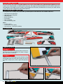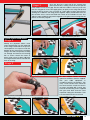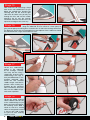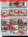
1
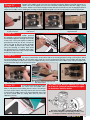
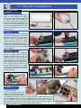
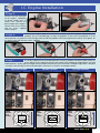
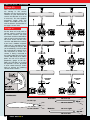
INSTRUCTION MANUAL
Suitable for Electric
or I.C. Engine Power
Congratulations on the purchase of your
Irvine Tutor 40 II Radio Control Model
Aircraft. Please take some time to carefully
read these instructions before assembly
and your first flights.
The Irvine Tutor 40 II is an ideal first model
or aileron trainer she will reward you with
many hours of superb flying and enjoyment!
Tutor 40 II Specification:
Wingspan..........................................62 3/8” (1635mm)
Length...............................................47 1/4” (1200mm)
Engine........................... .40-.46 2-Stroke (Not included)
Motor........................................ 700 watt (Not included)
Items required to complete the Tutor 40 II
Glow Engine version Requires
.40-.46 2-Stroke engine
4 Channel Proportional Radio Control System
Model Engine Fuel
Model Engine Starter and Glow Plug Battery (for Glowstart)
Hand Tools and Adhesive
Fuel tubing and propeller suitable for engine
Electric Conversion Requires
KMS Quantum 4120/05 Brushless Motor
Arrowind 60amp Electronic Speed Controller (ESC)
Intellect 4S 4000 25C Li-Po Flight Battery
4 Channel Proportional Radio Control System
12 x 6 Propeller
Part No: A-IRVTUT40/2
PLEASE READ CAREFULLY
This R/C aircraft is not a toy! If misused or abused, it can cause serious bodily injury and/or damage to property. Fly only
in open areas and preferably at a dedicated R/C flying site. We suggest having a qualified instructor carefully inspect your
aircraft before its first flight. Please carefully read and follow all instructions included with this aircraft, your radio control
system and any other components purchased seperately.
TOOLS AND MATERIALS REQUIRED
To complete the assembly of the Tutor 40 II, you will require a few hand tools and suitable adhesives:
•
•
•
•
•
•
•
Non-permanent marker pen
Clear tape or masking tape
Modelling knife
Small screwdrivers
Pair of pliers
Ruler and pencil
Tissue or cleaning cloth
Glues:
• 5 minute epoxy
• 30 minute or 1 hour epoxy
• Cyanoacrylate - super glue (medium)
KIT CONTENTS
JOINING THE WINGS
Stage 1
Locate the aluminium wing joining tube and insert it
half into one of the wing panels as shown. Using a
pen, half mark its centre line.
Stage 2
Apply plenty of 5 minute epoxy to one side of the wing
joining tube and insert it fully into the wing. Use tissue
or a cloth to wipe up any excess glue that squeezes
out.
1. Ensure tube is fully inserted in the wing
2.1.Apply sufficient epoxy to the centreline
marked in Stage 1
2
Irvine Tutor 40 II
2.2. Slide the tube fully into the wing
2.3. Wipe off any excess epoxy
Once the glue has cured, trial fit the second wing
panel onto the first, making sure that the two panels
meet without an excessive gap. File the end of the tube if necessary to ensure
that the wing panels meet. Now apply plenty of epoxy to the wing root rib and
the joiner tube as shown. Use 30 minute or 1 hour epoxy to give yourself extra
working time. Slide the two wing panels together. Epoxy should ooze from the
joint and the excess can be removed with a cloth or tissue before it cures. Use
adhesive tape to hold the two panels together as the glue cures ensuring that the
panels are correctly aligned.
Stage 3
3.1. Apply plenty of adhesive
3.2. Slide the second wing panel into place
3.3. Ensuring a close fit, use tape to ensure
alignment while the glue cures
4.1. Mark around the mount with a pen
4.2. Carefully cut through the film (NOT Wood)
4.3. Apply epoxy or cyano adhesive
4.4. Attach the mount in place
FITTING THE AILERON SERVO
Stage 4
Identify the plywood aileron servo
mount and position it on the underside
of the wing centralised to the pre-cut
servo aperture. Use a pen to mark the
position of the mount on the covering.
Using a ruler and a sharp knife, carefully
cut through and remove the covering
film as shown. Attach the mount in
place using cyano or epoxy adhesive
ensuring the lead cutout is towards the
front of the wing.
Stage 5
Fit the rubber servo mounting
grommets and brass ferrules supplied
with your radio equipment in
accordance with the instructions. Trim
away a small section of the mount for
the servo lead exit. Install the servo in
its mount and pilot drill (1.5mm) four
holes for the mounting screws supplied
with your servo. Now screw the servo
in position noting the orientation. Take
care not to drill into the servo lead.
5.1. Fit grommets and ferrules to the aileron servo
5.2. Trim the mount for the servo lead’s exit
5.3. Pilot drill the mounting holes
5.4. Screw the servo in position
Irvine Tutor 40 II
3
Identify the aileron link parts - two pushrods, aileron horns, two nylon snap links and two
swing-in keepers. Using a pair of pliers to hold the pushrod, screw on a nylon snap link until
the thread is just visible through the inside of the snap link. Repeat for the second pushrod. Now screw the two aileron
horns onto the torque rods already installed in the wing. Ensure that both are screwed on the same amount - they should
be approximately 30mm from the wing’s surface.
Stage 6
30mm
6.1. Screw on a snap link
6.2. Screw on the aileron control horns
6.3. Ensure the horns are screwed on equally
Stage 7
Connect up the aileron servo to the aileron channel in
the receiver, connect the receiver battery and turn on
the transmitter. Centre the aileron trims and make sure both ailerons are level.
Attach the first snap link to the aileron control horn as shown. Carefully mark
the position where the pushrod passes the servo’s control horn. Using a pair of
pliers, bend the pushrod 90° at this marked point. Using a pair of side cutters,
trim off the excess pushrod length, leaving 6mm after the bend.
7.3. Bend the pushrod 90 at this point
7.1. Connect the snap link
7.2.Mark the pushrod where it crosses the
control horn, 11mm from the servo centre
7.4. Trim off the excess length beyond 6mm
after the bend
Stage 8
Now connect the bent pushrod to the servo horn
using a hole approximately 11mm from the centre.
Slip a swing in keeper over the end of the pushrod and snap it closed over the
pushrod. Repeat this for the second pushrod, ensuring the ailerons remain level.
To complete the linkages, slip a short length of Silicon fuel tubing over each snap
link.
8.3. Complete the second pushrod in the
same way
8.1. Connect the pushrod to the servo horn
8.2. Snap on a keeper
FITTING THE TAILPLANE
8.4. Short length of fuel tube secures each
snap link
Stage 9
Using a sharp knife, carefully
remove the film covering
from the tail and fin slots
at the rear of the fuselage.
Make sure that you do not
remove any wood from the
slots as this will affect the
alignment of the tail and fin.
9.1. Trim the covering from the fin slot
4
Irvine Tutor 40 II
9.2. Trim the covering from the tail slots
Stage 10
Check the fit of the tail in its
slot. Make sure it is square
and centred to the fuselage
by taking measurements as
shown in the diagram but
don’t glue anything yet.
Equal Distance
10.1. Trial fit the tail in its slot
10.2. Alignment checks
11.1. Mark the top of the tail
11.2. Followed by the bottom
Stage 11
With the tail correctly
aligned, mark the shape of
the fuselage on the top and
the bottom of the tailplane
using a water-soluble/nonpermanent felt pen.
Stage 12
Now remove the tailplane and using a
sharp knife and a ruler CAREFULLY
cut 1mm inside the marked lines.
Remove the covering from the top and
the bottom of the tailplane. Make sure
you only cut through the film and not
the wood, otherwise the tailplane
may be severely weakened.
Stage 13
Now apply sufficient epoxy to the top
and bottom of the tailplane. Use 30
minute or 1 hour epoxy to give yourself
plenty of working time.
Insert the tail in its slot in
the fuselage and re-check
the alignment as in Stage
10. Excess adhesive should
be cleaned off with a rag or
tissue before it cures.
12.1. Carefully cut inside the marked lines.
DO NOT cut into the wood beneath!
12.2. Remove the film from the top of the
tailplane
Make sure it is the correct
way up.
13.1. Apply plenty of epoxy
13.2. Slide the tailplane in position
14.1. Mark the shape of the fuselage on the fin
14.1. Mark the shape of the fin on the fuselage
FITTING THE FIN
Stage 14
Trial fit the fin in its slot.
With the fin correctly
aligned, mark the shape of
the fuselage on both sides
of the fin using a watersoluble/non-permanent
felt pen. Mark the shape
of the fin extension on the
fuselage too.
Irvine Tutor 40 II
5
Stage 15
Now remove the fin and using a sharp
knife and a ruler CAREFULLY cut just
below the marked lines. Remove the
covering from the left and the right
side of the fin. Make sure you only cut
through the film and not the wood,
otherwise the fin may be severely
weakened. Remove the film from the
top of the fuselage in the same way.
15.1. Remove the film from the fin
15.2. Remove the film from the top of the fuselage
Stage 16
Now apply sufficient epoxy to both sides of the fin and
along the underside. Use 30 minute or 1 hour epoxy to
give yourself plenty of working time. Insert the fin in its slot in the fuselage and check
the alignment. Ensure that it is perpendicular to the tailplane. Excess adhesive should
be cleaned off with a rag or tissue before it cures.
16.2. Slide the fin in position
16.3.Remove any excess epoxy before it
cures
16.1. Apply plenty of epoxy
Stage 17
Locate the undercarriage
groove in the underside
of the fuselage. Carefully
trim away the film using a
sharp knife. Insert the main
undercarriage wire legs in
their pre-drilled holes in the
fuselage underside. Now
locate the two moulded
saddle clamps and hold in
position while marking the
fuselage for the mounting
holes. Pilot drill (1.5mm) the
holes for the saddle clamps
and screw in position.
17.1. Trim away the covering
17.2. Fit the undercarriage legs
17.3. Mark the position of the saddle clamps
17.4. Screw the clamps in place
18.1. Fit a collet to the axle
18.2. Retain the wheel with a second collet
Stage 18
Locate the wheel retaining
collets. Slide the first one on
to the undercarriage to just
before the bend and tighten
the retaining screw. Slide a
wheel on, then fit a second
collet, ensuring that the wheel
is free to spin. Add a drop
of cyano to each retaining
screw to secure
6
Irvine Tutor 40 II
Stage 19
Locate the nosegear steering arm and
connect it to the pre-formed z-bend in the
noseleg pushrod. Slide the pushrod into its
tube in the firewall and locate the steering
arm in the steering block with its retaining
screw forward. Slide the noseleg through
the first block, through the steering arm and
into the engine mount. With the steering
arm held in line with the axle, tighten the
retaining screw. There is a flat on the nose
leg wire facing the screw
19.1. Fit the steering arm on the pushrod
19.2. Install the steering arm
Stage 20
Fit a collet to the noseleg axle, slide a
wheel onto the axle and retain with a
second collet ensuring the wheel can
spin freely. Add a drop of cyano to
each retaining screw to secure.
19.3. Slide the noseleg in position
19.4. Tighten the steering arm’s screw
RADIO INSTALLATION
Stage 21
Locate the elevator and rudder control
horns. Turn the model upside down.
The elevator horn is fitted to the
underside of the left hand side of the
tail (looking from the underside with
model pointing away from you). Locate
the horn 25mm from the fuselage
20.1. Fit the nosewheel
centre-line and align its holes with the
hinge line as shown in the diagram. Mark the position of its mounting holes and
pilot drill the elevator. Screw the horn to the elevator noting that the screws selftap into the nylon plate on top. Remove any excess length of screw with side
cutters.
25mm From the
fuselage centerline
21.3. Horn aligned with the hinge line
21.1. Horn located under the elevator
21.2. Screw the horn in position
21.4. Screws self-tap into moulded plate on top
behind). Again its holes should be
aligned with the rudder hinge line, then
pilot drilled and screwed to the rudder
with a pair of screws terminating in a
moulded plate on the other side.
21.5. Clip off any excess
Stage 22
The rudder horn is fitted in exactly the
same way as the elevator. Note that
it should be located on the left hand
side of the rudder (when viewed from
22.1. Position the horn as shown
22.2. Screw in place
Irvine Tutor 40 II
7
Stage 23
Test fit your elevator and rudder
servos in the pre-fitted radio tray.
Note that the output horns are
orientated towards the front of the
model. Now fit the rubber grommets
and brass ferrules supplied with your
radio, pilot drill the servo tray and
screw the servos in position using
the screws supplied with your radio.
23.1. Test fit your servos in the tray
23.2. Pilot drill the tray then screw servos in position
Stage 24
Prepare the elevator pushrod by screwing a nylon clevis onto one end until the thread just
appears through to the inside of the clevis. Use a pair of pliers to hold the pushrod wire while
you do this. Locate the slot at the rear of the fuselage for the elevator pushrod and carefully trim away the covering as
shown. Now insert the pushrod into its pre-fitted guide tube. Temporarily attach the clevis to the elevator but do not snap
it shut yet.
24.1. Screw on a clevis
24.2. Trim away covering
24.3. Insert pushrod and connect to elevator
Stage 25
With the elevator held level and the elevator servo centralised, mark where the pushrod crosses
the servo’s control horn. Using a pair of pliers, bend the pushrod down through 90° at this point
and cut off any excess pushrod wire leaving a 6mm length after the bend. Now locate the pushrod in a hole in the servo
horn approximately 11mm out from the centre. Slip a nylon swing-in keeper over the pushrod and clip it to the pushrod
to retain.
25.1. Mark the pushrod where it crosses the
servo horn
25.2. Bend the pushrod at this point
25.4. Retain with a swing-in keeper
Stage 26
To complete the linkage, disconnect
the clevis from the elevator horn. Slide
a short piece of fuel tubing over the
clevis. Re-connect the clevis (centre 26.1. Disconnect the clevis
hole in the horn) and ensure that the
elevator is level with the elevator servo at its neutral position then snap the
clevis closed. Slide the tubing back over the clevis for additional security.
8
Irvine Tutor 40 II
25.3. Trim off the excess
26.2. Slip a length of fuel tubing over the clevis
26.3. Re-connect the clevis with the tube to secure
Prepare your rudder servo’s horn for the steerable noseleg by fitting a pushrod connector as
shown. Do not over-tighten the nut as the connector needs to pivot in the horn. Apply a small
drop of cyano on the nut to secure. With the servo and noseleg centred, slide the connector over the noseleg pushrod and
attach to the rudder servo. Holding the noseleg centred, tighten the grub screw in the connector to retain the pushrod.
Stage 27
27.1.Fit a pushrod connector
to your servo horn
27.2.Slide over the pushrod then
re-fit the horn
27.3.Tighten with an Allen key
27.4.Glue a block in place to
support the tube
Stage 28
Prepare the
rudder pushrod
by screwing a nylon clevis onto one end until
the thread just appears through to the inside
of the clevis. Use a pair of pliers to hold the
pushrod wire while you do this. Locate the
slot in the top of the rear of the fuselage
for the rudder pushrod and carefully trim
away the covering as shown. Now insert
the pushrod into its pre-fitted guide tube.
Temporarily attach the clevis to the rudder
but do not snap it shut yet.
28.1. Trim away covering
28.2. Insert pushrod and connect to the rudder
Stage 29
With the rudder held level and the rudder servo centralised, mark where the pushrod crosses
the servo’s control horn on the other side to the noseleg pushrod. Using a pair of pliers, bend
the pushrod down through 90° at this point and cut off any excess pushrod wire leaving a 6mm length after the bend.
Locate the pushrod in a hole in the servo horn approximately 11mm out from the centre. Slip a nylon swing-in keeper over
the pushrod and clip it to the pushrod to retain.
29.1. Mark the pushrod where it crosses
the servo horn
Stage 30
29.2. Bend the pushrod at this point and
trim off the excess
To complete the linkage, disconnect
the clevis from the rudder horn.
Slide a short piece of fuel tubing over the clevis. Re-connect
the clevis (centre hole in the horn) and ensure that the rudder
is level with the rudder servo at its neutral position then snap
the clevis closed. Slide the tubing back over the clevis for
additional security.
30.1. The completed rudder linkage
29.3. Retain with a swing-in keeper
You must now decide whether you wish
to fit an I.C. (internal combustion) engine
or brushless electric motor.
The Irvine Tutor 40 II is suitable for both Electric
Motors and I.C. Engines. The following sections cover
I.C. Engine installation and Electric Power.
Irvine Tutor 40 II
9
I.C. Engine Installation
I.C. ENGINE FITTING
Stage 1
Prepare the fuel tank by attaching a
length of clunk tubing to the unbent
tube on the tank bung. Using the tank
as a guide, trim the clunk tubing so
that when connected to it, the clunk is
free to move without touching the rear
of the tank. Now insert the bung in the
tank with the bent vent pipe to the top.
Tighten the retaining screw to seal the
bung in position.
1.1. Cut the clunk tube to length
1.2. Tighten the assembly screw
2.1. Mark the position of the mounting holes
2.2. Pilot drill the mount
2.3. Fit the throttle pushrod
2.4. Attach the engine
3.2. Retain it with the two velcro straps
3.3. Refit the hatch
Stage 2
Holding your engine centrally in position
on the pre-fitted engine mount, mark the
position of the mounting screw holes.
Pilot drill (2mm) the moulded engine
mount as shown. Attach the z-bent
throttle pushrod end to the engine’s
throttle arm, then feed the pushrod into
its tube in the firewall. Attach the engine
to its mount using the four self tapping
screws supplied.
Stage 3
Attach two lengths of fuel tubing to
the tank - one for feed and one for
pressure. Unlatch the hatch on the
underside of the model and slide the
tank into position ensuring the tubes
are not kinked as they pass through the
bulkhead. Retain the tank with the two
velcro straps already installed in the
fuselage. Refit the hatch. It is a good
idea to glue a small block of wood to
the tray behind the tank tp prevent it
sliding backwards.
3.1. Slide the tank into its bay
Stage 4
4.1. Fit a pushrod connector
to your servo horn
Prepare your throttle servo’s horn
by fitting a pushrod connector as
4.2. Install the throttle servo
shown. Do not over-tighten. Apply
a small drop of cyano on the nut to secure. Install the rubber grommets and
bushes supplied with your servo, then pilot drill the servo tray and screw the
servo in position using the screws supplied with your radio. Slip the throttle
pushrod connector over the pushrod and re-fit the throttle servo horn. Do not
fully tighten the grubscrew yet as the throttle is adjusted later.
10
Irvine Tutor 40 II
4.3. Slide connector over the pushrod then
re-fit the horn
I.C. Engine Installation
Stage 5
Connect the fuel feed pipe
to the engine’s carburettor
or remote needle valve as
shown here. Connect the
pressure pipe to the engine’s
silencer, then fit the silencer
with the screws supplied
with the engine.
5.1. Connect the fuel tube
5.2. Connect the pressure tube and install the silencer
Stage 6
Remove your engine’s prop nut and washer. Install the spinner backplate followed by your
propeller. Use the moulded pegs to align the propeller so that when the propeller is in the
correct position, the spinner cut-out will align correctly with the propeller. Re-fit your prop washer and nut, then tighten. Fit
the spinner nose with the two screws supplied.
6.1. Fit the spinner backplate
6.2. Fit your propeller and tighten
6.3. Re-fit the spinner nose
Stage 7
It is vitally important that the throttle operates correctly and does not bind at either end of its
travel. Switch on the radio and centralise the throttle stick. Holding the throttle barrel at its mid
throttle position, nip the grub screw tight in the pushrod connector. Use your transmitter’s end point adjustment - EPA/ATV
- (or adjust mechanically) so that the throttle opens and closes as shown in the diagrams below
(A) Low Throttle
(B) Mid Throttle
(C) High Throttle
LOW
MID
HIGH
Throttle
Stick
Position
Throttle
Stick
Position
Throttle
Stick
Position
Irvine Tutor 40 II
11
Electric Motor Installation
ELECTRIC MOTOR FITTING
Stage 1
Remove the pre-fitted IC engine
mount (4 bolts with spring washers
and washers). The mount and bolts
are no longer required but retain
the washers. Remove the battery
access hatch and remove the
captive nuts from behind the engine
mounting bulkhead. These will be
re-used to fit the electric motor.
1.1. Remove the engine mount screws
1.2. Remove the factory-fitted captive nuts
2.1. Mark the bulkhead for the motor mount
2.2. Drill the bulkhead for the mounting screws
Stage 2
By using the large fuel tank neck
location hole as a centre, mark the
positions of the mounting screws
on the bulkhead using the mounting
plate as a guide. If you are fitting
the recommended KMS motor
(quantum 4120/05), the two upper
holes for the IC mount are re-used
and only the lower ones need to be
drilled. Drill the mounting holes in
the bulkhead using a 5mm drill.
Stage 3
You will need to supply spacing
stand-offs for the motor you
have chosen. Motor lengths and fitting dimensions vary a lot
from make to make. For the KMS Quantum 4120/05 motor
they need to be 35mm long, 12mm wide with a 4.1mm internal
bore. For these spacers, you will need 45mm M4 bolts. You
can re-use the washers and spring washers from the original
mount. An optional spacer/screw kit is available with all that
you need for the KMS motor. Fix the captive nuts in the back
of new bulkhead holes and fit the motor using the screws
and washers detailed above (or appropriate to your motor).
Tighten the bolts so that the captive nuts are fully home in the
bulkhead. Do not let the wood of the bulkhead be crushed.
Stage 4
Fit the backplate of the spinner to the
propeller driver, then the propeller,
washer and nut. Note – The trailing
edge of the propeller should be in
contact with the small moulded posts
on the backplate. This is to align the
propeller with the cutouts in the spinner
cone. Make sure the main fixing nut
is securely tightened. Fix the spinner
cone to the backplate with the two self
tapping screws provided with it.
3.1. Fit the motor mount to the
motor
Stage 5
Complete the motor installation by
feeding the motor wires through the
hole in the bulkhead and into the
battery bay.
3.2. Fit the motor to the bulkhead
to use some more Velcro tape on the
face of the tray and the underside of the
battery (just 25mm is enough) to stop the
battery sliding. We also recommend fixing
a couple of balsa spacer blocks to the
rear of the bulkhead to prevent the battery
touching the captive mounting nuts and
bolts if it moves forward. Set the operation
of the motor/ESC by reference  to the ESC
instructions.
5.1. Motor wires go through the bulkhead
Stage 6
4.1. Fit the spinner backplate and propeller
12
Irvine Tutor 40 II
Mount the ESC (Electronic Speed
Controller) to the fuselage side using
adhesive foam tape. The battery is
retained in the tray by the Velcro
straps provided. It is a good idea
6.1. Attach your ESC with double sided tape
COMPLETING THE TUTOTR 40 II
Stage 31
Your radio switch (or
if you are using an
ESC with a switch) can now be mounted. The
radio tray has a pre-cut slot should you wish to
mount the switch internally and operate it with a
bent wire through the fuselage. The simplest way
of fitting the switch is simply mounting it through
the left-hand fuselage side (on the opposite
side to the exhaust). Using the switch plate as
a guide, mark and drill the mounting holes. Now
cut a suitable slot for the switch. Mount using
the screws supplied with the switch.
31.1. Use the switch as a guide for cutting
31.2. Fit the switch in the fuselage side
Stage 32
Locate the
pre-drilled holes
for the wing mounting dowels.
Using a sharp knife, trim the
covering away so the dowels can
be pushed through the fuselage
sides. Ensuring they are centrally
located in the fuselage, run some
medium super glue around each
to secure.
32.1. Trim away the covering
32.2. Insert the wing dowel
33.1. Mark the position of the first plate
33.2. Trim away the covering
Stage 33
To ensure that the trailing edge
of the wing is not crushed by
the wing mounting bands, two
plywood reinforcement plates are
used on the top surface. Holding
the first plate in position on the
wing with its rear aligned to the
trailing edge, mark its shape on
the surface of the wing using a
water-soluble/non-permanent felt
pen. Trim away the covering inside
the marked line and glue the plate
in position. Repeat for the second
plate.
Stage 34
Wrap your receiver and battery (if
using a separate battery for the 33.3. Repeat for the second side
receiver) in dense foam packing
and install in the fuselage under the
tank. The battery’s final position will be
determined once the model has had its
balance point checked.
34.1. Receiver battery wrapped in foam
34.2. And installed in tank bay
33.4. The completed wing
FINAL R/C SETUP
Stage 35
Before starting the final set-up of
the Tutor 40 II, switch on the radio
and ensure that all trims are in
their neutral positions. Check that
the ailerons, elevator and rudder
are centred. If any adjustments
are needed, do this by unclipping
the appropriate clevis and turning
it clockwise to shorten the linkage
or anti-clockwise to lengthen it.
Only when each control surface
has been centred mechanically
should you begin adjusting the
surface movements (or control
throws).
Irvine Tutor 40 II
13
FINAL R/C SETUP - CONTINUED
Stage 36
Now confirm the control surfaces
are moving in the correct
direction. Use the servo reversing
switches on your transmitter to
reverse the direction of a servo
if necessary. The most popular
transmitter mode (with the
throttle and rudder on the left,
with the ailerons and elevator on
the right) is shown here.
ELEVATOR UP
ELEVATOR DOWN
Stage 37
For the Tutor 40 II to fly well, its
control surfaces need to move
the correct amount. Too little
movement and the model will be
slow to react to your commands;
too much and it will be oversensitive and difficult to control.
If you have a modern computer
radio, then it is possible to finetune the settings to suit you. But
you should always set the model
up mechanically correctly first.
The movement, or ‘throw’ of a
surface is always measured at
the trailing edge (the rear) of the
surface and usually at its widest
point. You can use a ruler or a
proprietary gauge to do this.
Adjust the linkages by moving
the positions of the pushrods
in their control horns(as shown
here) to achieve the following
control surface throws:-
AILERON
DOWN
AILERON
UP
AILERON
UP
RUDDER
RIGHT
RUDDER
LEFT
AILERONS:
Elevator:
10 mm up
6 mm up
10 mm down
6 mm down
Rudder:
15 mm right
15 mm left
14
Irvine Tutor 40 II
AILERON
DOWN
BALANCING THE MODEL
Stage 38
Attach the wing using all the rubber bands
supplied, (although we do recommend the
use of white, silicon bands as they resist fuel and last longer. You can
obtain them from your local model shop) stretched diagonally across the
wing dowels. Now hold the model on your fingertips at a position 80mm
back from the the leading edge of the wing. The model should balance
slightly nose down. The receiver battery (or flight battery if flying with
electric power) can be moved slightly forwards or rearwards to achieve
this balance point without adding any extra weight. The importance of achieving the correct balance point cannot be
overstated. It is essential the model balances correctly before attempting to fly it! This check should always be carried
out with the flight battery in place when flying it with electric power and with the tank empty if flying it with I.C. engine
power.
FLYING THE TUTOR 40 II
Always fly the model in a safe and suitable location, away from houses, people and power
lines. It is always recommended that you enlist the help of a competent pilot and fly at a
recognised club. Before flying, check that the controls move in the correct direction, and the correct amount. Always
charge your radio equipment in accordance with the manufacturer’s recommendations and ensure that you are familiar
with the operation of your engine or motor before attempting to fly.
Stage 39
SAFETY
Always keep your hands and clothing clear of the spinning propeller. Fly safely and always maintain your model in good
condition by thoroughly cleaning the airframe between flying sessions and checking its condition before flying and
especially after a heavy landing.
NOTES
Irvine Tutor 40 II
15
Ripmax Ltd. guarantees this product to be free from manufacturer’s defects in both material and workmanship at the date of purchase.
This guarantee does not cover faults arising from misuse or accident and the guarantee does not cover damage or malfunction caused
by negligence, misuse, accident, unauthorised repair or modification. In no case shall Ripmax’s liability exceed the original cost of the
purchased kit. In that Ripmax has no control over the final use, no liability shall be assumed or accepted for any damage resulting from
the use of the product by the user. By the act of using the product, the user accepts all the resulting liability. If the purchaser of this
product is not prepared to accept the liability associated with the use of this product, they are advised to return this product immediately
in new and unused condition to the place of purchase.
The above guarantee in no way affects your statutory rights as a consumer.
Distributed in the UK and Europe by:
Ripmax Ltd.,
241 Green Street,
Enfield,
EN3 7SJ
United Kingdom
www.ripmax.com
Made in Vietnam