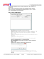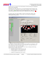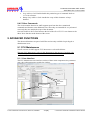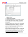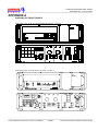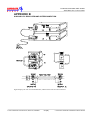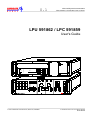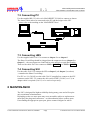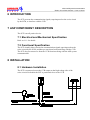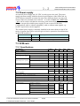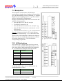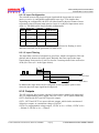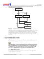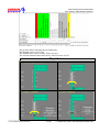
1
ASP® Manual Note: This page is blank for convenient double-sided printing. Safegate Group Date: July 2010 Version: 1.0 ASP® Manual Document: _ASP_INTRODUCTION ASP® CHAPTERS AND APPENDICES CONTENTS Section Description Preface ASP Introduction 1. ASP System General Description 2. AMT Pro-Basic user's guide 3. SFU User's Guide 4. LPU-LPC User's Guide 5. SCF User's Guide 6. SCM Rack - User's Guide 7. SIU User's Guide 8. LMS User´s Guide 9. MBD User's Guide 10. NCU User's Guide 11. ASP-system power line communication 12. International Standards Compliancy List 13. Case Description Turn-key ASP 14. ASP Modbus Interface 15. ASP System Preventive Maintenance 16. ASP Troubleshooting and Maintenance Page 1 of 6 Safegate Group Date: July 2010 Version: 1.0 ASP® Manual Document: _ASP_INTRODUCTION WARRANTY Project Warranty The Contractor (Safegate Group or subsidiary Company) hereby warrants that there shall be no significant failure or substantial reduction in performance in the following product or system, the performance criteria for which are as contained within the Project Contract. This Warranty shall commence on a specific date, and end on a specific date according to the Project Contract. The Contractor warrants to the Principal (Customer, agent or sub-contractor) that all work performed and all goods supplied by the Contractor under the above mentioned Project Contract will be: • at least of the quality and to the standard required by the Contract; and • of good workmanship and new and of merchantable quality; and • fit for the purpose or purposes for which they are required. All materials and workmanship are guaranteed against defect and malfunction for a period of twelve 12 months from the date of successful completion of a Site Acceptance Test (SAT) or of a period of eighteen 18 months from the date of shipment, whichever occurs first according to the Project Contract. Project Managers Member of the Safegate Group Subsidiary Company Product/System Warranty Safegate Group guarantees that the performance of the Safegate Group product/system, when sold by Safegate Group or its licensed representatives, meets the requirements of and is in compliance with agreed standards, such as ICAO. Note: For more information, contact Safegate for compliance with standards. Any defect in design, material or workmanship, which may occur during proper and normal use over a period covered by the warranty stipulated in the contract, will be replaced by Safegate Group free of charge, excluding works. Operational failure resulting from improper installation, damage due to user/operator error, airport maintenance equipment are not considered a result of proper use and is beyond the scope of the warranty. Any 3rd party products installed or integrated with functionality in a Safegate system without prior consent or support from Safegate causes the warranty to become invalid, as the design specifications can longer be guaranteed. The above constitutes the limits of Safegate Group liabilities concerning the Safegate Group products/systems. Product Leaders Member of the Safegate Group Subsidiary Company Page 2 of 6 Safegate Group Date: July 2010 Version: 1.0 ASP® Manual Document: _ASP_INTRODUCTION INTRODUCTION This manual has been compiled to give the reader an understanding of installation, operation and maintenance (IOM) procedures of Airfield Smart Power ASP®, with a focus on safety and efficiency. COPYRIGHT © Copyright 2010 by Safegate Group. All rights reserved. This item and the information contained herein are the property of Safegate Group. No part of this document may be reproduced, transmitted, transcribed, stored in a retrieval system, or translated into any language or computer language in any form or by any means otherwise, without the expressed written permission of Safegate Group, Djurhagegatan 19, SE-213 76 Malmö, Sweden. HISTORY Version 1.0 Date June 2010 Description First Release ORIGINAL DOCUMENTS The following is a list of original documents used to create this manual. File Name Description ASP_INTRODUCTION Introduction General Information 1. SG591890-3007A ASP System General Description 2. SG591891-3006D AMT Pro-Basic user's guide ASP System General Description 3. 591876-3001 SFU User's Guide SFU User's Guide AMT Pro-Basic user's guide 4. SG591862-3001 LPU-LPC User's Guide LPU-LPC User's Guide 5. SG591870-3002 SCF User's Guide SCF User's Guide 6. SG591883-3002B SCM Rack - User's Guide 7. SG591885-3018A SIU User's Guide SCM Rack - User's Guide 8. SG591886-3020A LMS User´s Guide LMS User´s Guide 9. SG596530-3011D MBD User's Guide MBD User's Guide 10. SG591943-3004A NCU User's Guide NCU User's Guide 11. ASP-system power line communication ASP-system power line communication 12. SG591890-3006 International Standards Compliancy List 13. SG591890-3013 Case Description Turnkey ASP 14. SG591890-3023H ASP Modbus Interface International Standards Compliancy List SIU User's Guide Case Description Turn-key ASP ASP Modbus Interface 15. SG591890-3014 ASP System Preventive ASP System Preventive Maintenance Maintenance 16. SG591890-3004 ASP Troubleshooting and ASP Troubleshooting and Maintenance Maintenance Note: This page is to be updated with every authorised change to the manual. Page 3 of 6 Safegate Group Date: July 2010 Version: 1.0 ASP® Manual Document: _ASP_INTRODUCTION SAFETY INFORMATION The airfield smart power (ASP) system is for airport safety and efficiency. The design is according to strict airport industry standards for the safety of, and use by authorised airport personnel. Airport Operations, Maintenance and other Authorised Personnel This information is a summary of the safety requirements on operation and maintenance personnel based on general electrical and safety precautions. Note: It is very important for authorised personnel to study this section before any operation or maintenance work on the system is commenced. ASP® should only be used by airport operations and maintenance personnel who have been properly trained in the use of the system. Safegate takes no responsibility for incorrect use of the system. All warnings contained in the text of this manual must be strictly observed. Airport operations and maintenance personnel are strongly advised to observe the following symbols and safety advisories. Symbol Safety Advisory ASP® contains electrical circuits and devices, which may be hazardous to operators and maintenance personnel, if proper safety precautions are not observed. Only properly trained personnel should open enclosures or attempt to perform maintenance on these devices. Personnel are cautioned to read and thoroughly understand this manual before attempting to service any part of the system. ASP® contains 100 - 230 VAC electrical circuits that may be hazardous to operators or maintenance personnel if proper safety procedures are not observed. Shut down power before attempting to service the system. Power may be turned off at the main disconnect circuit breaker or at the breaker panel supplying AC power to the unit or system. CAUTION: SOME SYSTEMS ARE SUPPLIED WITH A REMOTE UPS, WHICH MAY CONTINUE TO SUPPLY POWER TO THE SYSTEM, EVEN WHEN THE BREAKER AT THE SUPPLY PANEL IS SWITCHED OFF. BE SURE TO REMOVE ALL POWER, BEFORE SERVICING THIS EQUIPMENT. A chassis ground connection is provided in some parts of the system. Be sure to follow all applicable codes in making chassis ground connections. Page 4 of 6 Safegate Group Date: July 2010 Version: 1.0 ASP® Manual Document: _ASP_INTRODUCTION ABBREVIATIONS Abbreviation Description AC Alternate Current ACC Apron Control Centre ALB Aircraft Loading Bridge ASP Airfield Smart Power ATA Actual Time of Arrival ATD Actual Time of Departure A-SMGCS Advanced Surface Movement Guidance & Control System A-VDGS Advanced Visual Docking Guidance System CCR Constant Current Regulator CL Centre Line COTS Commercial Off-the-shelf Items CPU Central Processing Unit CR Communication Room CU Control Unit of Docking System CU Concentrator Unit DC Direct Current DGS Docking Guidance System ESD Electrostatic Discharge ETA Estimated Time Of Arrival ETD Estimated Time Of Departure FAT Factory Acceptance Test FIDS Flight Information and Display System GMS Gate Management System GOS Gate Operating System HMI Human Machine Interface I/O Input/ Output ICD Interface Control Document IOM Installation Operation Maintenance ISO International Standardisation Organisation IT Information Technology LCC Life Cycle Cost LCD Liquid Crystal Display LED Light Emitting Diode LMS Light Monitor- and Switch unit LRU Line Replaceable Unit MDT Mean Down Time MTBF Mean Time Between Failure MTTR Mean Time To Repair NTP Network Time Protocol OP Operator Panel unit Page 5 of 6 Safegate Group Date: July 2010 Version: 1.0 ASP® Manual Document: _ASP_INTRODUCTION Abbreviation Description PBB Passenger Boarding Bridge PCB Printed Circuit Board PD Pilots Display unit PLC Programmable Logic Controller P/N Part-number QCP Quality Control Plan RAM Random Access Memory RH Relative Humidity RVR Runway Visual Range SAT Site Acceptance Test SBU Safety Back-up SCF Series Circuit Filter SCM Series Circuit Modem SMGCS Surface Movement Guidance & Control System SSU System Switch Unit S/N Serial Number SQL Structured Query Language STA Scheduled Time of Arrival STD Scheduled Time of Departure TCP/IP Transmission Control Protocol/Internet Protocol U/S Unserviceable/ Out of Service UPS Uninterruptible Power Supply Page 6 of 6 ASP LMS System Documentation ”ASP-System Concept / General Description” ASP-System Concept General Description © 2002 SAFEGATE International AB, Östersund, SWEDEN 1. SG591890-3007A ASP SYSTEM GENERAL DESCRIPTIONX 30.06.2010 15:22:00 ASP LMS System Documentation ”ASP-System Concept / General Description” CONTENTS 1 2 3 4 5 6 Revision History ............................................................................................................................... 3 Scope ................................................................................................................................................. 3 Abbreviations .................................................................................................................................... 3 References ........................................................................................................................................ 4 Introduction ....................................................................................................................................... 4 Basic System Characteristics ......................................................................................................... 4 6.1 The LMS ...................................................................................................................................... 4 6.2 The SIU ....................................................................................................................................... 5 6.3 The SCM and CU ........................................................................................................................ 5 6.3.1 Redundant CU ..................................................................................................................... 5 6.4 The SCF ...................................................................................................................................... 5 6.5 Control System Interface ............................................................................................................. 5 6.6 Flexibility ...................................................................................................................................... 6 6.7 Availability ................................................................................................................................... 6 6.8 Installation Requirements and Maintainability ............................................................................. 7 6.9 Failsafe Operation ....................................................................................................................... 7 7 Communication Principles .............................................................................................................. 8 7.1 System Response Times ............................................................................................................ 9 7.1.1 Stop Bar Response Time ..................................................................................................... 9 7.1.2 Lamp Monitoring Response Time ........................................................................................ 9 7.1.3 Command Sequence Response Time ................................................................................. 9 8 Appendices ..................................................................................................................................... 10 8.1 Elements Of Importance ........................................................................................................... 10 8.1.1 Field Equipment ................................................................................................................. 10 8.1.1.1 Power Consumption ................................................................................................... 10 8.1.1.2 Encapsulation ............................................................................................................. 10 8.1.1.3 Sensor Interfacing ....................................................................................................... 10 8.1.1.4 Communication Technique ......................................................................................... 11 8.1.1.5 System Configuration ................................................................................................. 11 8.1.1.6 Functionality ................................................................................................................ 12 8.1.1.7 Flexibility ..................................................................................................................... 13 8.2 Vault Equipment ........................................................................................................................ 13 8.2.1.1 Installation ................................................................................................................... 13 8.3 System Response Times .......................................................................................................... 14 8.3.1.1 Single Command Response Time .............................................................................. 14 8.3.1.2 Sensor Response Time .............................................................................................. 14 8.3.1.3 Failed Lamp Response Time ...................................................................................... 14 8.3.1.4 Multi Segment Response Time................................................................................... 14 © 2005 SAFEGATE International AB, Östersund, SWEDEN 2 (14) 1. SG591890-3007A ASP SYSTEM GENERAL DESCRIPTIONX ASP LMS System Documentation ”ASP-System Concept / General Description” 1 REVISION HISTORY Ver Date Remark Author 0.1 0.2 1.0 1.1 020130 020130 020204 050121 Document created, draft. Added Appendices. Issued. Added details in chapter 8.1 JF OH OH JF 2 SCOPE This document is intended to provide a general description of the ASP-System concept provided by Safegate. 3 ABBREVIATIONS ASP LMS SIU SCM SCF CU SSU PLC CCR SMGCS A-SMGCS Airfield Smart Power Light Monitor- and Switch unit Sensor Interface Unit Series Circuit Modem Series Circuit Filter Concentrator Unit System Switch Unit Programmable Logic Controller Constant Current Regulator Surface Movement Guidance Control System Advanced SMGCS © 2005 SAFEGATE International AB, Östersund, SWEDEN 3 (14) 1. SG591890-3007A ASP SYSTEM GENERAL DESCRIPTIONX ASP LMS System Documentation ”ASP-System Concept / General Description” 4 REFERENCES SG591835-3013 LMS User’s Guide SG591870-3002 SCF User’s Guide SG591880-3003 SCM-Rack User’s Guide SG591885-3018 SIU User’s Guide SG591847-3017 CU User’s Guide SG591852-3018 SSU User’s Guide SG591890-3006 International Standards Compliancy List 5 INTRODUCTION The ASP-System is designed to provide individual monitoring of airfield lighting using the series circuit as a means of communication for the lamp and sensor status information coming from the airfield. The same concept is used for lighting control, and as such provides the foundation for an SMGCS or ASMGCS which includes for example automation of stop bars with or without sensors, taxiway guidance (routing), both in combination with status monitoring. The ASP-System is a cost effective solution for upgrading existing or new series circuits with selective switching and/or individual monitoring of all or a selected number of lights in an airfield. 6 BASIC SYSTEM CHARACTERISTICS Refer to Figure 1 for reference. For more detailed information regarding the ASPSystem components refer to the individual User’s Guides. 6.1 The LMS The ASP-System, using the LMS concept, is designed to provide selective switching and/or monitoring of airfield lighting by use of an addressable switching unit at each individually controlled light. This switching unit is the LMS. The LMS is connected to the secondary side of a standard series circuit isolation transformer, connected to the series circuit, and uses standard 2-pin FAA-style connectors for its connection between isolation transformer and the attached light fixture. Communications to/from the LMS uses a unique power line communication technique developed by Safegate where the communication signals are superimposed on the series circuit current. © 2005 SAFEGATE International AB, Östersund, SWEDEN 4 (14) 1. SG591890-3007A ASP SYSTEM GENERAL DESCRIPTIONX ASP LMS System Documentation ”ASP-System Concept / General Description” 6.2 The SIU Sensors for presence- and direction detection of aircraft and vehicles on the airfield can easily be interfaced to the ASP-System using an SIU. The SIU communicates the detect/no-detect status signals as well as its own status to the series circuit in the same manner as the LMS. The SIU is also connected the secondary side of a standard isolation transformer using the standard 2-pin FAAstyle connectors while its connection to the sensor is established using an IP68 rated 7-pin connector. The SIU can supply the sensor with a DC-voltage since it also includes a current to voltage converter. 6.3 The SCM and CU The CU, as its name suggests, concentrates all status information coming from the field, i.e. both lamp and sensor status. It transfers commands to the SCM, which constitutes the interface to the series circuit. The SCM interfaces to the series circuit through a standard isolation transformer and to the CU via standard RS485 or RS232 serial communication. 6.3.1 Redundant CU The SSU is included in an ASP-System in order to introduce redundant CU control functionality of the associated SCMs. Its role is to control the switching of the CU-to-SCM communications between the active CU and the SCMs. 6.4 The SCF The SCF is connected across the CCR series circuit output and is used to contain the communication signalling within the airfield circuit and minimize feedback into the regulator. 6.5 Control System Interface The CU operates as the ASP-System main interface interpreting commands sent from the Host/Supervisor System (including the Safegate SafeControl-system) and in turn controlling the appropriate LMS lighting as directed. It maintains all lighting and error status as well as that of sensor detections as reported from the airfield components and thus is the central point of the ASP-System as operated from each vault. As such, individual lights can be grouped in lighting segments spanning one or more series circuits, for example an interleaved stop bar. In turn, the CU provides alarm status for percentage and adjacent lamp failure within those defined lighting segments per requirements for low visibility operations. Airfield lighting and ASP-System component status are constantly monitored and updated to the Host/Supervisor system upon occurrence. © 2005 SAFEGATE International AB, Östersund, SWEDEN 5 (14) 1. SG591890-3007A ASP SYSTEM GENERAL DESCRIPTIONX ASP LMS System Documentation ”ASP-System Concept / General Description” Host Lighting Control PLC/Tower-Control Greyed area not part of ASP system Vault Host Lighting Control PLC/Vault-Control CU ... CU RS23 ... Parallel RS485 SSU CCR CCR SCF SCF RS485 SCM DET SIU RWY/TWY LMS Lamp Figure 1 ASP-System block diagram (redundant CU-configuration depicted). 6.6 Flexibility The fact that the segmentation of lights into selectively controlled blocks is made in software, and not by means of cables and CCRs or selector switches, reduces the installation and hardware costs substantially and at the same time increases the flexibility of the airfield lighting system. A segment can easily be redefined or added in the software, with possible addition of isolation transformers and LMSs in the airfield. Not all lights on a series circuit need to be equipped with LMSs, only the ones that need to be monitored/controlled. The ASP-System is designed to be modular and expandable, so that it can be readily modified to monitor and control additional lighting functions and series circuits. 6.7 Availability The series circuit cable transfers power to the lamp on the circuit and the same physical channel is used by the ASP-system for communication. This implies that whenever there is power available to the lamps, the ASP-system will have access to its communications channel and control and monitoring will be available. A discontinuity on the cable shield will not normally influence neither the light’s nor the ASP-system’s availability. © 2005 SAFEGATE International AB, Östersund, SWEDEN 6 (14) 1. SG591890-3007A ASP SYSTEM GENERAL DESCRIPTIONX ASP LMS System Documentation ”ASP-System Concept / General Description” The system is designed to operate without repeaters, which boosts availability considerably compared to systems that require them. 6.8 Installation Requirements and Maintainability The ASP-system’s electrical requirements on a series circuit level are the same as a light fitting’s or an isolation transformer’s 1. Thereby the ASP-System does not put any additional constraints on how the installation is done and hence there is no conflict with for example electrical safety code and general or local standards when installing this type of system. The Safegate ASP-system may be used on shielded as well as unshielded cables and there are no constraints when it comes to grounding the shield since it’s not used by the system. High voltage equipment (connected to the primary of the series circuit) and low voltage equipment (connected to the secondary of the series circuit) are physically separated. By separating them, the impact on system availability and person hazards as a consequence of maintenance efforts, is minimized. 6.9 Failsafe Operation If a fault is detected on any system component at any time, the CU will provide this information to the Host-System upon occurrence so that the appropriate actions may be taken. These actions would typically be that of displaying a message to the maintenance station terminal and, if necessary, some indication at the operator terminals to signify any interference to operations. In normal operations, the ASP lighting appears on the airfield as commanded by the Host-System. When there is an equipment or communications failure associated with the ASP-System, the associated airfield lighting adopts the failsafe or “safe-state” setting. This can happen on an individual circuit basis or the entire airfield depending upon one or more of the following circumstances: 1. A “Set Failsafe” command is given by the Host-System: The CU sets airfield lighting to a predefined failsafe state as commanded by the HostSystem. The airfield remains in this state under Host-System control until the airfield lighting is commanded to another state. 2. Loss of communications with the Host-System: The CU assumes an error in the Host-System control and sets airfield lighting to its predefined Failsafe state. The airfield remains in this state under ASP-System control until communications is restored with the Host-System AND the airfield lighting is commanded to another state. 3. Loss of control operations by the CU: Both redundant CU computers or their application are turned OFF but the ASP-System circuits remain ON. In such case, the signalling on the series circuit from the SCM will cease due to lack of CU/SCM communications thereby forcing the LMS to assume their pre-programmed Failsafe state (the pre-programmed failsafe state matches that as would be commanded). 1 Safegate has a set of general recommendation or preferences regarding for example cable routing, which may be applied in case a new series circuit is to be designed. © 2005 SAFEGATE International AB, Östersund, SWEDEN 7 (14) 1. SG591890-3007A ASP SYSTEM GENERAL DESCRIPTIONX ASP LMS System Documentation ”ASP-System Concept / General Description” 4. Loss of SCM, SCF, or related component in series circuit interface OR SCM communications with the CU: In such case, ASP signalling on the series circuit will cease as a result of the hardware failure thereby forcing the LMS to assume their pre-programmed “Failsafe” state. 7 COMMUNICATION PRINCIPLES The information exchange is performed according to the structure shown below in Figure 2. Host Computer System Order Status System Status Alarm/ Pre Alarm Segment On/Off Segment/ Detector On/Off CU/ SCM#/ Com/ LMS/ SIU/SSU OK/ Fail Message CU (Concentrator Unit) Order Status System Status Segment On/Off SCM-ID, Lamp-ID, Detector On/ Off SCM-ID, LMS-ID, SIU-ID OK/Fail SCM (Series Circuit Modem) Order Status Segment On/Off Lamp/LMS-ID, SIU/Detector On/Off/OK/Fail LMS/SIU (Airfield Components) Figure 2 ASP-System information exchange. The communication between the components at the different levels is such that the higher level device always polls the lower level device, evaluates the answers, and determines the on/off and pass/fail status for the functions or components © 2005 SAFEGATE International AB, Östersund, SWEDEN 8 (14) 1. SG591890-3007A ASP SYSTEM GENERAL DESCRIPTIONX ASP LMS System Documentation ”ASP-System Concept / General Description” below. If a unit fails to report within a predetermined amount of time, it is assumed to be failed until reported otherwise. The evaluation of conditions is performed at the lowest level possible and information condensed before transferred upward so as to minimize response times and transfer of information between each unit. 7.1 System Response Times The ASP-System is designed to provide up to date status information on individual lamps as well as light functions independently of the commanded lamp state, i.e. no matter if the lamp is commanded on or off. This implies that provided the system (and series circuit) is energized, status on lights and light functions is continuously available. The user of the system will not only be able to control desired light functions but will also know beforehand in what shape the system is in terms of operational readiness. Hence maintenance efforts may be launched as soon as any deficiencies are detected and well before the affected light functions are needed operationally. The ASP-System is designed to comply with operational requirements in terms of response times. In the chain of events including air traffic controller reaction→ system response time→ physical changes in the field→ pilot reaction, the system response time constitutes a minor part. Time critical functions like stop bar control have priority over less critical functions like for example runway edge light monitoring. Response times are measured from the ASP-System interface from the point in time when a command is received to the point in time when the corresponding status information (true fed back) is available. The only exception to the above is when a SafeControl-control system is host in which case the response time includes host processing and overhead as well. In this case the response time is equivalent to the system response time. 7.1.1 Stop Bar Response Time Maximum stop bar response time from receiving a command to true back indication is 2 s, typically less than 1 s. Sensor detection is typically reported within 1 s. The stop bar response time applies to both interleaved and noninterleaved configurations. 7.1.2 Lamp Monitoring Response Time A lamp failure is detected and reported within 5s regardless of system configuration. 7.1.3 Command Sequence Response Time Maximum response time for any light function command from receiving the command to true back indication is 10 s. This applies regardless of the number of light segments involved. In case the light function only affects a few segments the maximum response time is considerably lower. For single segment response time in general refer to 7.1.1. © 2005 SAFEGATE International AB, Östersund, SWEDEN 9 (14) 1. SG591890-3007A ASP SYSTEM GENERAL DESCRIPTIONX ASP LMS System Documentation ”ASP-System Concept / General Description” The consequence of the above is that in an ASP-system it is always possible to predict the maximum response time regardless of the system configuration. 8 APPENDICES 8.1 Elements Of Importance Below some important general aspects of smart lights (ASP) worth considering are listed. The Safegate ASP-System complies with all requirements. 8.1.1 Field Equipment Equipment installed in the field, i.e. typically in hand holes, cans or man holes, are referred to as field equipment. Examples of such equipment are the LMS and the SIU. 8.1.1.1 Power Consumption Requirement: The power consumption for a field unit shall be less than 10W for all operating conditions. Argument: Reduces or eliminates need for upgrading CCRs and isolation transformers due to increased power consumption when smart lights are added to an existing circuit. 8.1.1.2 Encapsulation Requirement: The field unit shall have insulating, non-conductive encapsulation. Argument: To avoid electrical hazard and increase personal safety. Requirement: The field unit shall be completely sealed. Argument: For protection against the effect of long periods of immersion (IP 68). 8.1.1.3 Sensor Interfacing Requirement: The field sensor interface unit shall be able to monitor/control external sensors, as well as work as power supply for sensor. Argument: To decrease the number of electronic devices in the field. © 2005 SAFEGATE International AB, Östersund, SWEDEN 10 (14) 1. SG591890-3007A ASP SYSTEM GENERAL DESCRIPTIONX ASP LMS System Documentation ”ASP-System Concept / General Description” 8.1.1.4 Communication Technique Requirement: The communication with field units shall be through signals superimposed on the series circuit. Argument: No extra communication cables or connectors are needed in the harsh environment out in the field, which minimizes maintenance and maximizes reliability. No special procedures are needed for repairing or replacing connectors and/or cables. Requirement: The communication shall not be dependent of a continuous primary cable screen Argument: The screen of the primary cable cannot be guaranteed to be continuous. Requirement: The communication with field units shall rely on a circuit modem at one end, inside the substation, and field units that individually and independently of each other communicate through the power cable with the circuit modem without any additional repeaters/amplifiers placed in the field. Argument: A failure of a single field unit must not affect the overall circuit communication. One failed field unit must not affect the availability of the system any worse than one failed lamp. 8.1.1.5 System Configuration Requirement: All lights or just a selected number of light fixtures on a circuit shall be able to be equipped with field units. Argument: Makes the system more flexible, for example if only lead-on lights on a taxiwaycircuit needs to be controlled. Requirement: If any link in an ASP system or control system fails, the system shall automatically go to a predefined failsafe state. The predefined state (ON or OFF) shall be able to be individually programmed for the field units. Argument: For safety reasons. © 2005 SAFEGATE International AB, Östersund, SWEDEN 11 (14) 1. SG591890-3007A ASP SYSTEM GENERAL DESCRIPTIONX ASP LMS System Documentation ”ASP-System Concept / General Description” Requirement: The field units shall be able to be individually programmed with a predefined power-up state, ON, OFF or last commanded state. The field unit shall be able to remember its last commanded state at power losses for up to 20 seconds. Argument: For safety reasons. The power-up state of the lamps must be well defined even if other parts of the system are down. The field unit must be able to remember its last commanded state at short power losses, for example when switching between mains power and generator-set power. Requirement: The field units shall use standard isolation transformers and standard connectors. 8.1.1.6 Functionality Requirement: The field units shall be able to withstand the same current levels as isolation transformers are required to, i.e. 7.1 ARMS continuously and 8.2 ARMS for max 1 second. Argument: In accordance with FAA advisory circular 150/5345-47A (Isolation transformers for airport lighting systems) the maximum continuous current supported is 7.1 ARMS. Additionally the LMS is designed to withstand current transients in accordance with FAA advisory circular 150/5345-10E (Specification for CCRs and regulator monitors) implying 5% over current or 6.9 ARMS for max 5 seconds (overruled by the 7.1 ARMS requirement presented above) and 25% over current or 8.2 ARMS for max 1 second Requirement: The field units shall automatically detect a failed lamp. When the failed lamp is replaced the field unit shall automatically detect this as well and no additional procedure shall be required to make the system aware of that the lamp has been replaced. Argument: To guarantee maximum availability the system shall be able to handle low level functionality (such as failed lamp detection) automatically without user intervention. This way maintenance will be efficient and the users of the system can focus on the operational aspects of running the airport. Requirement: The field unit must be able to report ON/OFF/FLASH/FAIL state of the lamp, and FAIL state of the field unit. © 2005 SAFEGATE International AB, Östersund, SWEDEN 12 (14) 1. SG591890-3007A ASP SYSTEM GENERAL DESCRIPTIONX ASP LMS System Documentation ”ASP-System Concept / General Description” Requirement: The field unit must be able to command the lamp to ON/OFF/FLASH state. In addition to that, if lamp is commanded flashing, the system must be able to keep the flashing lamp synchronized according to FAA advisory circular 150/5340-28 requirements for Runway Guard Lights systems. 8.1.1.7 Flexibility Requirement: The field unit performance must not depend on the grounding scheme used for isolation transformers or light fixtures. Argument: The field unit must not compromise personal safety requirements or electrical code requirements and hence it shall support grounded isolation transformers or fixtures as well ungrounded ones. Requirement: The system shall support a feature that minimizes sudden load changes, experienced by the CCR, on the circuits. This feature shall not decrease system response times. Argument: A sudden increase in load due to switching ON a large number of lights on a circuit can make the CCR trip because of undercurrent. In the same way, a sudden decrease in load due to switching OFF a large number of lights on the circuit can make the CCR trip because of overcurrent. These mentioned discrepancies are not accepted from an operational point of view, and decreases the lifetime of the CCR, lamps and field units. Because the CCRs on the market show great differences in coping with sudden load changes, a feature like that must be completely independent of CCR type, regulating characteristics etc. It shall not be acceptable to affect the CCR by external signals to solve the problem, it is for example possible to prepare the CCR before a sudden decrease in load by temporarily decrease the CCR output current, but this solution will give a observable light intensity change that cannot be acceptable from an operational point of view. 8.2 Vault Equipment Equipment installed in a vault or a sub station is referred to as vault equipment. Examples of such equipment are the SCM, the SSU and the CU. 8.2.1.1 Installation Requirement: Any active equipment connected to the series circuit must connect to the secondary of a standard isolation transformer. Active equipment such as modems must not be connected to the primary. Argument: © 2005 SAFEGATE International AB, Östersund, SWEDEN 13 (14) 1. SG591890-3007A ASP SYSTEM GENERAL DESCRIPTIONX ASP LMS System Documentation ”ASP-System Concept / General Description” No single unit on a series circuit must in case of failure be allowed to jeopardize the integrity of the circuit itself. By always connecting active equipment such as modems, to the secondary of an isolation transformer the result of a failure will be no worse than a failed lamp in terms of series circuit integrity, i.e. the series circuit itself will not be affected, nor will the CCR. Requirement: High voltage equipment (connected to the primary) shall be physically separated from low voltage equipment (connected to the secondary of an isolation transformer). Argument: High voltage and low voltage maintenance procedures are different and each one, when carried out, affects the availability of the system in different ways. By separating high voltage and low voltage equipment physically, the impact on system availability as a consequence of maintenance efforts is minimized. For example, if a modem needs maintenance the circuit is not affected and the CCR may be operated without constraints. 8.3 System Response Times The airfield light control system shall be built to meet the operative demands and needs regarding response times. This means that time critical functions like stopbar functions shall be given priority to, unlike less time critical functions like pure monitoring of lights. 8.3.1.1 Single Command Response Time The response time for a command to be executed, such as a stop-bar command shall be 1 second from that the controller pushes the button until the light is switched. The acknowledgement from that the stop-bar light is switched until this is indicated on the controllers screen shall be 1 second. 8.3.1.2 Sensor Response Time The time to detect an activated incursion sensor shall be 1 second. 8.3.1.3 Failed Lamp Response Time The response time for indication of a failed lamp shall be 5 seconds. 8.3.1.4 Multi Segment Response Time Multi-segment state change response times should always be less than 5s (from the command is sent to all lights have switched) no matter the number of involved segments/lights. As an extreme all lights on a single circuits shall be able to change state on command independently of each other and regardless of the desired light pattern and the number of lights involved, in less than 5s. Multisegment state change including true feedback shall be completed in less than 10s. © 2005 SAFEGATE International AB, Östersund, SWEDEN 14 (14) 1. SG591890-3007A ASP SYSTEM GENERAL DESCRIPTIONX Productdocumentation AMT 591891 ”AMT Basic-Pro / User's Guide” AMT Basic-Pro User's Guide © 2004 SAFEGATE International AB, Östersund, SWEDEN 2. SG591891-3006D AMT PRO-BASIC USER'S GUIDE Productdocumentation AMT 591891 ”AMT Basic-Pro / User's Guide” Contents 1 2 3 4 5 6 Revision history................................................................................................................................ 4 Scope ................................................................................................................................................. 4 Application ........................................................................................................................................ 4 Abbreviations .................................................................................................................................... 4 References ........................................................................................................................................ 4 Introduction ....................................................................................................................................... 5 6.1 Requirements .............................................................................................................................. 5 6.2 Installation ................................................................................................................................... 5 6.3 Different variants of AMT ............................................................................................................ 5 6.3.1 AMT Basic ............................................................................................................................ 5 6.3.2 AMT Pro ............................................................................................................................... 5 7 The user interface............................................................................................................................. 5 7.1 Login ............................................................................................................................................ 5 7.2 Main window................................................................................................................................ 6 7.2.1 To adjust the main window .................................................................................................. 6 7.2.1.1 Undock .......................................................................................................................... 7 7.2.1.2 Dock .............................................................................................................................. 7 7.2.1.3 Hide windows ................................................................................................................ 8 7.2.1.4 Show window ................................................................................................................ 8 7.2.1.5 Save Layout .................................................................................................................. 8 7.2.1.6 Lock Layout................................................................................................................... 8 7.3 Communication settings .............................................................................................................. 8 7.3.1 Monitoring ............................................................................................................................ 8 7.3.2 Control and Monitoring ......................................................................................................... 8 7.4 System Configuration .................................................................................................................. 9 7.4.1 The Configuration Tree ........................................................................................................ 9 7.4.2 Search in the Configuration ................................................................................................. 9 7.5 Log window ............................................................................................................................... 10 7.6 Tools Window ............................................................................................................................ 10 7.6.1 LPU Manager ..................................................................................................................... 10 7.6.2 FCU Inspector .................................................................................................................... 11 7.6.3 SCM Inspector ................................................................................................................... 11 7.6.4 LPC I/O .............................................................................................................................. 12 7.6.5 Circuit Monitor .................................................................................................................... 12 7.6.5.1 Advanced Logging ...................................................................................................... 13 7.6.5.2 Review Logged data ................................................................................................... 14 7.6.6 Circuit Tuning ..................................................................................................................... 15 7.6.7 Self Hosted SCM................................................................................................................ 15 8 To use AMT ..................................................................................................................................... 15 8.1 Maintain LMS/SIU/SLIQ ............................................................................................................ 16 8.1.1 Programming and test procedure ...................................................................................... 16 8.1.1.1 Programming an LMS in Remote Control (Automatic) Mode ..................................... 16 8.1.1.2 Programming a SIU in Remote Control (Automatic) Mode ........................................ 17 8.1.1.3 Programming a SLIQ .................................................................................................. 18 8.1.1.4 Programming an LMS in Manual Mode ...................................................................... 19 8.1.1.5 Programming a SIU in Manual Mode ......................................................................... 20 8.1.2 Testing Functions ............................................................................................................... 21 8.1.2.1 LMS Function Test ...................................................................................................... 21 8.1.2.2 SIU Function Test ....................................................................................................... 22 Remote Control Mode ................................................................................................................... 22 Manual Mode ................................................................................................................................ 23 8.2 SCM MAINTENANCE ............................................................................................................... 23 8.2.1 SCM Maintenance ............................................................................................................. 23 8.2.1.1 Activating SCM Maintenance...................................................................................... 23 8.2.1.2 SCM Maintenance Sequence ..................................................................................... 24 © 2004 SAFEGATE International AB, Östersund, SWEDEN 2 (50) 2. SG591891-3006D AMT PRO-BASIC USER'S GUIDE Productdocumentation AMT 591891 ”AMT Basic-Pro / User's Guide” 8.2.1.3 Troubleshooting SCM Maintenance ........................................................................... 24 8.2.2 Loading SCM Firmware ..................................................................................................... 25 8.2.3 Advanced Maintenance ..................................................................................................... 26 8.2.3.1 Loading SCM Configuration........................................................................................ 26 8.2.3.2 Loading SCM parameters ........................................................................................... 27 8.3 CIRCUIT MAINTENANCE ........................................................................................................ 28 8.4 Circuit Monitor ........................................................................................................................... 28 8.4.1 Monitoring Circuit Communication ..................................................................................... 28 8.4.1.1 Evaluation of monitored communication ..................................................................... 31 8.4.2 Sending Commands .......................................................................................................... 32 8.4.3 FCU Version Query ............................................................................................................ 32 8.4.4 Menu Command Reference ............................................................................................... 32 8.4.5 Other Commands ............................................................................................................... 33 9 Advanced functions ....................................................................................................................... 33 9.1 FCU Maintenance ..................................................................................................................... 33 9.1.1 User Interface..................................................................................................................... 33 9.1.1.1 The Configuration Pane .............................................................................................. 34 9.1.1.2 The FCU Parameter Pane .......................................................................................... 34 9.2 Circuit Tuning ............................................................................................................................ 36 9.2.1 Why circuit tuning? ............................................................................................................. 36 9.2.1.1 ASP system power cable communication .................................................................. 36 9.2.1.2 Circuit tuning principles ............................................................................................... 36 9.2.1.3 Frequency tuning ........................................................................................................ 36 9.2.1.4 A word of caution ........................................................................................................ 36 9.2.2 Frequency tuning by AMT .................................................................................................. 37 9.2.2.1 Hardware setup .......................................................................................................... 37 9.2.2.2 AMT frequency tuning principles ................................................................................ 37 9.2.2.3 Before starting AMT frequency tuning sequence ....................................................... 37 9.2.2.4 AMT frequency tuning sequence ................................................................................ 37 10 Self Hosted SCM ......................................................................................................................... 44 10.1 Configuration functionality ..................................................................................................... 45 10.2 Monitoring functionality .......................................................................................................... 46 11 User handling .............................................................................................................................. 46 11.1 User groups ........................................................................................................................... 46 12 Appendix ...................................................................................................................................... 47 12.1 LPU ........................................................................................................................................ 47 12.1.1 Hardware setup for Manual Mode...................................................................................... 47 12.1.2 Hardware setup for Remote Control Mode ........................................................................ 47 © 2004 SAFEGATE International AB, Östersund, SWEDEN 3 (50) 2. SG591891-3006D AMT PRO-BASIC USER'S GUIDE Productdocumentation AMT 591891 ”AMT Basic-Pro / User's Guide” 1 REVISION HISTORY Ver Date Remark Author 1.0 2004-06-17 Translated tools windows information JF A 2004-10-07 Updated screen-shots and some LPU-prog texts Added chapter about evaluation of monitored signal levels MH/JF B 2005-07-05 Added description in DB Explorer about log window information. Updated window texts which have been changed. SL C 2005-12-02 Updated information in chapter 13.5.3.1 and 13.5.3.2. SL D 2010-02-25 Added instruction of how to program SLIQ using Production ID. SL 2 SCOPE This document describes the software ASP Maintenance Tool (AMT 591819), its functionalities and use. 3 APPLICATION This document is intended for users that are well acquainted with the ASP-system. As AMT is created to simplify and increase efficiency at maintenance, commissioning and troubleshooting, the document is mainly for users that work with these activities. Figures, function descriptions etc in this document is based on version 3.3 of AMT which implies that earlier versions not necessary work or look as described here. In those cases, consult the user manual for the earlier version. 4 ABBREVIATIONS ASP AMT CCR CU SCM FCU LMS SIU LPU LPC SFU Airfield Smart Power ASP Maintenance Tool Constant Current Regulator Concentrator Unit Series Circuit Modem Field Communication Unit (LMS or SIU) Light Monitor and Switch unit Sensor Interface Unit LMS/SIU Programming Unit (consists of an SCM and an LPC) LPU Control Unit Signal Filtering Unit 5 REFERENCES SG591891-3001 1 AMT User’s Guide 1 Describes earlier AMT versions, before 3.0 © 2004 SAFEGATE International AB, Östersund, SWEDEN 4 (50) 2. SG591891-3006D AMT PRO-BASIC USER'S GUIDE Productdocumentation AMT 591891 ”AMT Basic-Pro / User's Guide” 6 INTRODUCTION 6.1 Requirements Following are the operative systems that are supported by AMT: • Windows 98 • Windows 2000 Professional • Windows NT 4.0 Workstation • Windows XP Professional In addition to that, the computer that AMT is running on must have: • Monitor resolution at least 800 × 600. • • Serial Communication Port Fontsize small size or 96 DPI. If other size is used, some of the windows in AMT can be distorted and/or impossible to read. 6.2 Installation Run the installation program setup.exe from the CD that AMT is delivered with. That will install AMT on the hard disc and add a program group on the start menu, called Safegate. 6.3 Different variants of AMT In principal, AMT comes in two versions. The difference between them is the number of tools included. Exactly what is included in each variant is determined by Safegate. 6.3.1 AMT Basic The AMT Basic variant is intended for the user that only needs to program spare parts to an ASP system. That includes programming of LMS, SIU and SCM. Alternatively or as a complement, tools can be included for configuration and monitoring of stand-alone ASP system, so called Self Hosted SCM. 6.3.2 AMT Pro The AMT Pro includes (in addition to what is supported by the Basic variant) also tools for commissioning, monitoring and troubleshooting of the ASP system and its components. 7 THE USER INTERFACE This section describes the user interface, and briefly describes the functionality that the different tools provide. 7.1 Login When AMT is started up, the user is asked to login with his username and password. © 2004 SAFEGATE International AB, Östersund, SWEDEN 5 (50) 2. SG591891-3006D AMT PRO-BASIC USER'S GUIDE Productdocumentation AMT 591891 ”AMT Basic-Pro / User's Guide” See section 13 for more information about the administration of users and user groups. 7.2 Main window If the username and login is correct, the main window is shown. The main window consists of three parts: • To the left is a section for communication settings (Connection Manager) and system configuration (System Inspector) • To the right is a section for different tools. Each tool has its own flap. • Down at the bottom is a log window. In the top of the main window is a menu with a number of shortcut buttons. 7.2.1 To adjust the main window The user has some freedom to adjust the look of AMT. The user can choose: • between the tools on the flaps and other functions integrated/docked in the main window or each of the tools in separate windows or a combination of the two • which of the tools and other functions that will be visible © 2004 SAFEGATE International AB, Östersund, SWEDEN 6 (50) 2. SG591891-3006D AMT PRO-BASIC USER'S GUIDE Productdocumentation AMT 591891 ”AMT Basic-Pro / User's Guide” 7.2.1.1 Undock First check that the alternative Lock layout on the View-menu is deselected – not until then a tools window can be undocked. To undock e.g. a tools window from its flap, double-click on the flap, then the tool will get its own window. Alternatively drag and drop with left mouse button. The undocked window will always remain on top of the main window, so to be able to reach the main window; the undocked window may have to be moved. Note that if either both Connection Manager and Inspector or Log-window is undocked, the tools section will grow to the left and/or down. 7.2.1.2 Dock To dock a tools window to the main window, grab the name list of the window and drag it to the upper right corner of the main window. A frame is shown in the main window. Drop the name list and the window is docked and gets its own flap. If the Log window is intended to be docked, drag it to the bottom part of the main window. When both the Connection Manager and System Inspector is separate windows and one of them is supposed to be docked, it must be dragged to the left part of the main window. Note that not all windows can be docked everywhere: • The tools windows can only be docked to the right part of the mains window • Connection Manager and System Inspector can be docked either to the right or to the left part of the mains window. • The Log window can only be docked at the bottom part of the main window. © 2004 SAFEGATE International AB, Östersund, SWEDEN 7 (50) 2. SG591891-3006D AMT PRO-BASIC USER'S GUIDE Productdocumentation AMT 591891 ”AMT Basic-Pro / User's Guide” 7.2.1.3 Hide windows To hide a window, either click on the cross in the upper right or left corner or deselect the window in either the View- or Tools-menu. 7.2.1.4 Show window To show a window, select the window in either the View- or Tools-menu. 7.2.1.5 Save Layout If Save Layout is selected in the View-menu, the program will start with the same layout as when it was shut down the last time before. 7.2.1.6 Lock Layout By selecting Lock Layout in the View-menu, tools windows can neither be docked or undocked. This does not influence the possibilities to show or hide windows. Every time AMT is started, Lock Layout will be activated. If the user wants to change the layout, Lock Layout must first be deselected. 7.3 Communication settings In order to get AMT to work correctly, there must be an active connection to a SCM. That is irrespective if AMT is connected to a LPU or an ASP system. Use Connection manager to specify what type of connection there is, and what COM-port is used on the computer. Is AMT connected to a LPU, select LPU. Is AMT connected to an ASP system, select either “Monitoring” or “Control and Monitoring”. To activate all functionalities in AMT, AMT must be run in”Control and Monitoring”-mode. Actual state of the connection to the SCM is shown at the bottom of Connection Manager. 7.3.1 Monitoring When AMT is connected to an ASP system “monitoring”, meaning that the ASP system is operative, AMT is only listening to the operative communication (Listen Mode). To avoid interference with the operative communication, all commanding functionality in AMT are blocked in the “monitoring”-mode. Every time AMT is started, “Monitoring” mode is pre-selected, and the user must by himself select “Control and monitoring” mode. WARNING! Note that the front switch on the SCM “RS485/RS232” (alt. ”REMOTE/LOCAL”) must remain in RS485 to avoid interference with an operative system. By setting the switch to RS232 (LOCAL), the SCM will be taken out of operative running. 7.3.2 Control and Monitoring In opposite to “Monitoring”, “Control and Monitoring” means that AMT have exclusive access to the part of the system that is controlled by the SCM. © 2004 SAFEGATE International AB, Östersund, SWEDEN 8 (50) 2. SG591891-3006D AMT PRO-BASIC USER'S GUIDE Productdocumentation AMT 591891 ”AMT Basic-Pro / User's Guide” When”Control and Monitoring” is selected, there are no functional restrictions comparing to the ”Monitoring” mode. Every time the user is changing from ”Monitoring to “Control and monitoring”, a dialogue window appears that asks the user to acknowledge before the change is made, to secure that ”Control and monitoring” mode is not selected by mistake. 7.4 System Configuration A system configuration contains information about the different components in the system, mainly LMS and SIU. Many of the tools in AMT need access to a system configuration to be able to work correctly. System Inspector is used to load the system configuration, to navigate in it and in some cases to manipulate it. The window is consisting of two parts: • At the top is a search field. • At the bottom is a tree structure where the configuration is shown. 7.4.1 The Configuration Tree The content of the configuration is shown in a tree structure where the uppermost level symbolises the site. Below that level is the different circuits, and on the bottom level is the lamps and sensors. By selecting a lamp or sensor in the tree, it will automatically be active and available by all tools in AMT. To the left of every lamp and sensor, there is an icon that symbolises the object. If the user clicks with the right mouse button on an active lamp or sensor, a small menu turns up where a number of selections are available: • Collapse All: Compress the tree so that only the uppermost level is visible. • Expand All: Expands the tree so that all levels are visible. • Auto Expand: If this function is active, all circuits will be compressed except the selected circuit. • Clear Status: Resets the status indication that is shown to the left of the symbols for the object (lamp or sensor). 7.4.2 Search in the Configuration Write the complete or beginning part of the name in the search field and press enter. The first occurrence of the text string is shown by highlighting the object in the configuration tree. © 2004 SAFEGATE International AB, Östersund, SWEDEN 9 (50) 2. SG591891-3006D AMT PRO-BASIC USER'S GUIDE Productdocumentation AMT 591891 ”AMT Basic-Pro / User's Guide” 7.5 Log window The log window is used to show events that either is initiated by the user or is a result of an action made in a tools window. All events are time stamped and the log is accumulative, which means that every time AMT is started, the log from the preceding session is opened and continued. Thereby, the log will be a user’s history for AMT on a specific computer. 7.6 Tools Window The tools in AMT are gathered in different tools windows. The type of tool and its use is determining which tools window it belongs to. Some tools are available from several windows. Tool windows available in AMT are: • LPU Manager • FCU Inspector • SCM Inspector • LPC I/O • Circuit Monitor • Circuit Tuning • Self Hosted SCM 7.6.1 LPU Manager The LPU Manager tool window is only used when AMT is connected to a LPU. The purpose of the window is to provide the user functionality for programming, verifying and test of LMS and SIU. The functions in this window are only available when the LPU connection in Connection Manager is selected. © 2004 SAFEGATE International AB, Östersund, SWEDEN 10 (50) 2. SG591891-3006D AMT PRO-BASIC USER'S GUIDE Productdocumentation AMT 591891 ”AMT Basic-Pro / User's Guide” LPU Manager can remotely control the LPU for automatic handling of the programming- and verifying sequences. FCU Type allows the user to select the type of FCU (Field Communication Unit) to be programmed. The button Download Parameters will start the programming sequence. 7.6.2 FCU Inspector In the case the parameters of an individual LMS or SIU need to be reviewed, edited or verified, the FCU Inspector provides access to every parameter and a couple of advanced programming- and verifying tools. 7.6.3 SCM Inspector SCM Inspector provides access to individual SCM-parameters and functionality for down- and uploading of these parameters. As an addition, there is functionality for downloading of SCM firmware. © 2004 SAFEGATE International AB, Östersund, SWEDEN 11 (50) 2. SG591891-3006D AMT PRO-BASIC USER'S GUIDE Productdocumentation AMT 591891 ”AMT Basic-Pro / User's Guide” 7.6.4 LPC I/O The LPC I/O window provides direct control of certain buttons on the LPC provided. This is mainly for test purpose. 7.6.5 Circuit Monitor One of the most versatile and useful tools is Circuit Monitor. This tool provides monitoring as well as control of all units on the series circuit to which AMT is connected. The tool provides graphic presentation of signal- and noise levels, statistics and an advanced log function. © 2004 SAFEGATE International AB, Östersund, SWEDEN 12 (50) 2. SG591891-3006D AMT PRO-BASIC USER'S GUIDE Productdocumentation AMT 591891 ”AMT Basic-Pro / User's Guide” 7.6.5.1 Advanced Logging Data can be logged in a database for later evaluation. That includes raw data as well as status on system level. The logging can be initiated either manually or be programmed to start/stop at a specific time. Every logging sequence is time stamped with start- and stop time. Information about who has initiated the log as well as information about what AMT-version and computer have been used is also saved. The user must also state some Meta Data concerning the series circuit, CCR, filter units etc. If the user wants to, the log can be restricted to only include status changes for the system components. That is an advantage when long logging sequences are carried out, as the amount of logged data will be less extensive. © 2004 SAFEGATE International AB, Östersund, SWEDEN 13 (50) 2. SG591891-3006D AMT PRO-BASIC USER'S GUIDE Productdocumentation AMT 591891 ”AMT Basic-Pro / User's Guide” 7.6.5.2 Review Logged data By using the DB Explorer, the user can easily navigate to a specific logging sequence to be able to evaluate it. Uppermost in DB Explorer is a list of carried out logging sequences sorted by date. By selecting a sequence in Directory, supplementary details can be added in the Meta Data fields, CCR, SFU and other. When a specific logging sequence is selected in Directory, Data will show high level information from the selected circuit, as well as raw data. Every event is individually time stamped. Comments can be added to any event. The Data window includes the following information: Time Stamp: Time stamp identifies when data in displayed record was captured. ID: FCU ID Type: LMS/SIU State: Indicates lamp state for LMS and detection state for SIU State Change: Level: State change identified with reference to previous record Signal level Com Fail: Number of communication failures Com Count: Number of communication repetitions Start: Indicates when capture was stared for data to which the displayed record belongs Comment: User Comment To the right in DB Explorer there are functions for filtering. Filtering can be based on: • Date and time © 2004 SAFEGATE International AB, Östersund, SWEDEN 14 (50) 2. SG591891-3006D AMT PRO-BASIC USER'S GUIDE Productdocumentation AMT 591891 ”AMT Basic-Pro / User's Guide” • System ID • State • State change • Signal level • Communication fail percentage • System component type • Comment Filtering can also be based on a combination of the above, and then only events that fulfil all selected criteria will be shown. A filtered log can be exported to a separate database that can be sent by email or equivalent. Similarly, data can be imported to an existing database. This data will then be chronologically sorted in relation to the existing data in the database. Selected log sequence can also be replayed in Circuit Monitor to get a graphical view of the communication. 7.6.6 Circuit Tuning Circuit Tuning is a process that is used at commissioning of ASP system, the Circuit Tuning tool provides fully automatic functions for that purpose. 7.6.7 Self Hosted SCM Some types of ASP system can be configured without a NCU. In those cases, the SCM will handle many of the functionalities that are normally handled by the NCU. The Self Hosted SCM tool includes functionality to configure the SCM as well as monitor the resulting system functionality. 8 TO USE AMT This section describes a number of common tasks, and how to solve them with use of AMT and its functionalities. © 2004 SAFEGATE International AB, Östersund, SWEDEN 15 (50) 2. SG591891-3006D AMT PRO-BASIC USER'S GUIDE Productdocumentation AMT 591891 ”AMT Basic-Pro / User's Guide” 8.1 Maintain LMS/SIU/SLIQ To maintain LMS/SIU/SLIQ is mainly to program spare parts, modify parameters and test suspected malfunctioning units. The following applies only when using the LPU version consisting of an LPC and an SCM interconnected, for programming LMS:es, SIU:s, SLIQ:s and maintaining SCM’s. Designations for the switches corresponds to SCM 591813B and LPC version 3. Appendix A shows a layout of the different versions of the SCM and LPC. New Designation SCM RS485/RS232 LPC Remote LPC LAMP 1 LPC LAMP 2 Old designation Remote/Local Remote/Local LOAD 1/LAMP 1 LOAD 2/LAMP 2 8.1.1 Programming and test procedure 8.1.1.1 Programming an LMS in Remote Control (Automatic) Mode If you need to program a large number of LMS:s, then the Remote Control Mode will help you to simplify and speed up the process. In this mode the AMT software will automatically turn the LPC switches on/off, etc. Connect the hardware as described in section 14.1.2 Hardware setup for Remote Control Mode. In the Settings menu you also need to activate the Remote Control LPC item. 1. 2. 3. 4. 5. 6. 7. 8. At the programming screen you first need to select the correct configuration in the System panel. Multiple choices for FCU Type are available. Select LMS. Release the LAMP 1 or LAMP 2 buttons on the LPC if any of these buttons is pressed in. Connect the LMS male connector to an OUTPUT outlet on the LPC. Connect the LMS female connector to an LMS outlet on the LPC. You also need to identify the individual LMS you intend to program. You do this by either writing the id in the Find field to search for it or select the id in the System panel list. Press the Download Parameters button to start the programming sequence. A message box allows you to click on the Cancel button to stop the download sequence if you would like to do so. If you want to continue the download sequence, click on the Continue button, see Figure 1. Figure 1. Confirm parameter download. © 2004 SAFEGATE International AB, Östersund, SWEDEN 16 (50) 2. SG591891-3006D AMT PRO-BASIC USER'S GUIDE Productdocumentation AMT 591891 ”AMT Basic-Pro / User's Guide” 9. A hardware initialisation is started only if the option Skip Version Control is deselected. The LMS version is identified and the optimal parameters for communication with the LMS are set. When the LMS version dialog box is displayed you click the OK button to start the parameter download sequence. If the Skip Version Control is active then no version control is performed. 10. After downloading the parameters, which can take up to a minute a checksum check will be done to ensure that the LMS has received the new parameters. If the checksum is correct a message box is shown to confirm this. 11. If the checksum is OK the LMS may be disconnected. To program another LMS repeat this procedure from step 4 above. However, if a message box tells you that the checksum is incorrect then you need to reprogram the same LMS unit from step 7 above. 8.1.1.2 Programming a SIU in Remote Control (Automatic) Mode If you need to program a large number of SIU:s, then the Remote Control Mode will help you to simplify and speed up the process. In this mode the AMT software will automatically turn the LPC switches on/off, etc. Connect the hardware as described in section 14.1.2 Hardware setup for Remote Control Mode. In the Settings menu you also need to activate the Remote Control LPC. 1. At the programming screen you first need to select the correct configuration in the System panel. 2. Multiple choices for FCU Type are available. Select SIU. 3. All IN and OUT buttons as well as LAMP 1 and LAMP 2 on the LPC should be released. 4. Connect the SIU male connector to an OUTPUT outlet on the LPC. 5. Connect the SIU sensor interface connector to the SIU outlet on the LPC. 6. You also need to identify the individual SIU you intend to program. You do this by either writing the id in the Find field to search for it or select the id in the System panel list. 7. Press the Download Parameters button to start the programming sequence. 8. A message box allows you to click on the Cancel button to stop the download sequence if you would like to do so. If you want to continue the download sequence, click on the Continue button, see Figure 2. Figure 2. Confirm parameter download. 9. A hardware initialisation is started only if the option Skip Version Control is deselected. The SIU version is identified and the optimal parameters for communication with the SIU are set. When the SIU version dialog box is displayed you click the OK button to start the parameter download sequence. If the Skip Version Control is active then no version control is performed. © 2004 SAFEGATE International AB, Östersund, SWEDEN 17 (50) 2. SG591891-3006D AMT PRO-BASIC USER'S GUIDE Productdocumentation AMT 591891 ”AMT Basic-Pro / User's Guide” 10. After downloading the parameters, which can take up to a minute a checksum check will be done to ensure that the SIU has received the new parameters. If the checksum is correct a message box is shown to confirm this. 11. If the checksum is OK the SIU may be disconnected. To program another SIU repeat this procedure from step 4 above. However, if a message box tells you that the checksum is incorrect then you need to reprogram the same SIU unit from step 7 above. 8.1.1.3 Programming a SLIQ The programming of parameters is done in the LPU Manager window in AMT. 1. Make sure the Remote button on the LPC is not pressed (off) before you start programming. 2. Connect the LMS male connector to an OUTPUT outlet on the LPC. 3. From the configuration list select the correct light parameter name to configure. Note: The product may require configurations of both sides or only one side. Parameter name __A is for A-side and __B is for B-side of SafeLED IQ. 4. 5. Check the bottom of the SafeLED IQ for Production ID (PID) number. Enter the PID Number in the text field 6. Press the Download Parameters button to start the programming sequence. 7. Click Continue to confirm parameter download, see Figure 3. Figure 3. Confirm parameter download. 8. After downloading the parameters, which can take up to a minute a checksum check will be done to ensure that the SLIQ has received the new parameters. If the checksum is correct a message box is shown to confirm this, see Figure 4 above. 9. If the checksum is OK the LMS may be disconnected. To program another LMS repeat this procedure from step 4 above. However, if a message box tells you that the checksum is incorrect then you need to reprogram the same LMS unit from step 7 above. © 2004 SAFEGATE International AB, Östersund, SWEDEN 18 (50) 2. SG591891-3006D AMT PRO-BASIC USER'S GUIDE Productdocumentation AMT 591891 ”AMT Basic-Pro / User's Guide” 8.1.1.4 Programming an LMS in Manual Mode 1. At the programming screen you first need to select the correct configuration in the System panel. 2. Multiple choices for FCU Type are available. Select LMS. 3. Connect the LMS male connector to an OUTPUT outlet on the LPC. 4. Connect the LMS female connector to an LMS outlet on the LPC. 5. You also need to identify the individual LMS you intend to program. You do this by either writing the id in the Find field to search for it or select the id in the System panel list. 6. Press the Download Parameters button to start the programming sequence. 7. A message box is shown to remind the user to turn on the OUTPUT POWER on the LPC, see Figure 3. Figure 4. Turn on OUTPUT POWER switch. 8. Follow the instructions on the screen for controlling the LAMP switch on the LPC, see Figure 4. Figure 5. Instructions for controlling the LAMP switch. 9. A hardware initialisation is started only if the option Skip Version Control is deselected. The LMS version is identified and the optimal parameters for communication with the LMS are set. When the LMS version dialog box is displayed you click the OK button to start the parameter download sequence, see Figure 5. Figure 6. Found LMS If the Skip Version Control is active then no version control is performed. 10. After downloading the parameters, which can take up to a minute a checksum check will be done to ensure that the LMS has received the new parameters. If the checksum is correct a message box is shown to confirm this, see Figure 6. © 2004 SAFEGATE International AB, Östersund, SWEDEN 19 (50) 2. SG591891-3006D AMT PRO-BASIC USER'S GUIDE Productdocumentation AMT 591891 ”AMT Basic-Pro / User's Guide” Figure 7. Checksum OK 11. If the checksum is OK the LMS may be disconnected. To program another LMS repeat this procedure from step 3 above. However, if a message box tells you that the checksum is incorrect then you need to reprogram the same LMS unit from step 6 above. 8.1.1.5 Programming a SIU in Manual Mode 1. At the programming screen you first need to select the correct configuration in the System panel. 2. Multiple choices for FCU Type are available. Select SIU. 3. All IN and OUT buttons as well as LAMP 1 and LAMP 2 on the LPC should be released. 4. Connect the SIU male connector to an OUTPUT outlet on the LPC. 5. Connect the SIU sensor interface connector to the SIU outlet on the LPC. 6. You also need to identify the individual SIU you intend to program. You do this by either writing the id in the Find field to search for it or select the id in the System panel list. 7. Press the Download Parameters button to start the programming sequence. 8. A message box is shown to remind the user to turn on the OUTPUT POWER on the LPC, see Figure 7. Figure 8. Turn on OUTPUT POWER switch. 9. Follow the instructions on the screen for controlling the PROG switch on the LPC, see Figure 8. Figure 9. Instructions for controlling the PROG switch. 10. A hardware initialisation is started only if the option Skip Version Control is deselected. The SIU version is identified and the optimal parameters for © 2004 SAFEGATE International AB, Östersund, SWEDEN 20 (50) 2. SG591891-3006D AMT PRO-BASIC USER'S GUIDE Productdocumentation AMT 591891 ”AMT Basic-Pro / User's Guide” communication with the SIU are set. When the SIU version dialog box is displayed you click the OK button to start the parameter download sequence, see Figure 9. Figure 10. Found SIU If the Skip Version Control is active then no version control is performed. 11. After downloading the parameters, which can take up to a minute a checksum check will be done to ensure that the SIU has received the new parameters. If the checksum is correct a message box is shown to confirm this, see Figure 10. Figure 11. Checksum OK. 12. If the checksum is OK the SIU may be disconnected. To program another SIU repeat this procedure from step 4 above. However, if a message box tells you that the checksum is incorrect then you need to reprogram the same SIU unit from step 7 above. 8.1.2 Testing Functions If Remote Control Mode is used the three test functions described below will automatically operate the switches on the LPC. If however Manual Mode is used the user have to manually operate the OUTPUT POWER switch on the LPC. The Remote button can also be used to set if Remote Control Mode should be used or not. Note that the Remote switch on the LPC must be set to the same position. 8.1.2.1 LMS Function Test © 2004 SAFEGATE International AB, Östersund, SWEDEN 21 (50) 2. SG591891-3006D AMT PRO-BASIC USER'S GUIDE Productdocumentation AMT 591891 ”AMT Basic-Pro / User's Guide” First choose the correct FCU Id in the list. Then press Start to start the communication with the LMS. The status returned from the LMS is shown to the right of Status. There is three different states: ON (also implies to FLASH), OFF and LAMP FAIL (also implies to com. Error). The LMS can be controlled by using any of the three command buttons: ON, OFF and FLASH. If Remote Control Mode is activated you can click on the LAMP 1 / 2 buttons to disconnect the lamp. The LMS should then report LAMP FAIL. If Remote Control Mode is not activated the user must manually control the LAMP 1 / 2 buttons on the LPC. 8.1.2.2 SIU Function Test First choose the correct FCU Id in the list. Then press Start to start the communication with the SIU. The status returned from the SIU is shown to the right of Status. There are three different states: Detect, No Detect and Com. Error. There are eight buttons for controlling the four outputs on and off (OUT 1 to OUT 4). Only the outputs that are controllable in the SIU parameters are enabled. Remote Control Mode SIU Voltage shows the SIU output voltage. For a more accurate reading use the multimeter connection on the LPC. IN 1 to IN 4 control the SIU inputs on the LPC. The color of the text in the buttons states what status the SIU is reporting for that particular input: Black font : Waiting for report from SIU. Green font : The SIU reports with the same status as the current input. Red font : The SIU reports with incorrect status. INPUT LOGIC has the same function as the corresponding switch on the LPC. That is to choose if the buttons IN 1 to IN 4 should be lit or not when the button is pressed in. © 2004 SAFEGATE International AB, Östersund, SWEDEN 22 (50) 2. SG591891-3006D AMT PRO-BASIC USER'S GUIDE Productdocumentation AMT 591891 ”AMT Basic-Pro / User's Guide” LOAD 1 and LOAD 2 is used for loading the SIU voltage output. The voltage shown to the right of SIU Voltage may drop slightly if any of the loads are activated. The load will automatically be turned off after about 10 seconds. PROG has currently no function in Remote Control Mode. Manual Mode IN 1 to IN 4 shows the SIU reported status for that particular input. The answer is coded in three different colors: Green font : The SIU reports that the current input is on. Organge font : The SIU reports that the current input is off. Red font : The SIU does not answer. 8.2 SCM MAINTENANCE 8.2.1 SCM Maintenance The term SCM Maintenance refers, in this document, to the process of replacing an SCM-board or an entire SCM unit and thereto-related configuration. An SCM-board or an SCM unit is configured, through software, in accordance with the requirements set by the individual ASP-system in terms of functionality and performance. This implies that if an SCM-board or an SCM unit is replaced the new board/unit will have to get a configuration matching that of the replaced board/unit for correct function in the system. The configuration process consists of a few steps (of which two are described in section 8.2.3.1 and 8.2.3.2), all possible to perform independently and/or manually if needed. To facilitate the configuration process AMT supports an automatic configuration process where the user only has to specify which SCM to configure. 8.2.1.1 Activating SCM Maintenance For correct operation make sure that the SCM about to be configured is connected to the PC running AMT before SCM Maintenance is activated. When the SCM is connected, check that it’s powered on and confirm the position of the switch marked RS232/RS485 2 to be RS232. Activate SCM Maintenance from within AMT by selecting SCM Configuration from the menu or press F1. 2 Earlier versions of the SCM-board have the switch marked Local/Remote, which corresponds to RS232/RS485. © 2004 SAFEGATE International AB, Östersund, SWEDEN 23 (50) 2. SG591891-3006D AMT PRO-BASIC USER'S GUIDE Productdocumentation AMT 591891 ”AMT Basic-Pro / User's Guide” Figure 12. SCM Maintenance view from AMT. Figure 13 shows the SCM Maintenance display and it’s divided into three separate areas.The top left portion contains the Site, Target and Action panels. Here the user selects site and SCM-target units to specify which SCM to configure. The button Set Up SCM starts the configuration process. To the right the Preferences area contains a range of options for customizing the configuration process. Normally the check box labeled Manual Configuration is unchecked. Note that depending on how AMT is configured the Manual Configuration option may not be available at all in which case the panel is empty. The last area at the bottom is devoted to Status information in the form of a log file window. The log file will show all user actions as well configuration process status and error messages. Note that the log file is saved every time AMT is terminated and hence it shows SCM Maintenance history in addition to current activities. Right below the Status information window a progress indicator is located. 8.2.1.2 SCM Maintenance Sequence Provided that AMT is communicating with the SCM-board about to be configured the process consists of three simple steps: 1. Select site and SCM from the combo boxes labeled Site and Target. When an SCM is selected the circuit to which it’s associated is shown to the right of the Target combo box. 2. Start the configuration process by pressing the Set Up SCM button. The configuration will normally take between two and ten second to complete. 3. Verify the proper completion of the configuration process by observing the messages displayed in the Status window. 8.2.1.3 Troubleshooting SCM Maintenance The SCM Maintenance feature in AMT relies on the existence of an INI-file, which contains the site specifics of the configuration process. Secondly all individual SCM configuration files for the particular site(s) must be available to AMT. Both the INI-file © 2004 SAFEGATE International AB, Östersund, SWEDEN 24 (50) 2. SG591891-3006D AMT PRO-BASIC USER'S GUIDE Productdocumentation AMT 591891 ”AMT Basic-Pro / User's Guide” and the SCM configuration files are normally included in the AMT-distribution for a particular site. If any of these files are missing or if there is any other kind of problem the Status window will display detailed information about the problem. To solve the problem please contact Safegate support for assistance. 8.2.2 Loading SCM Firmware • • • • Load Firmware starts loading of software to the SCM. Firmware Loader sets the way the SCM is set to firmware loading mode. The option bootload cable (bootload cable with LOAD/RESET switch) should always be used. Firmware Version shows the software version of the currently loaded firmware in the SCM. Cancel cancels a firmware download. 1. To load firmware to an SCM a Bootload Cable (part no 591869) is needed. 2. Make sure Firmware Loader is set to Bootload Cable. 3. Press Load Firmware and select the correct firmware file with the filename format “*.A07”. 4. A message box is shown to confirm loading of new firmware. 5. Press LOAD (the red LED should be lit) and RESET on the bootload cable black box to start software download. The download may take up to 10 minutes to finish. © 2004 SAFEGATE International AB, Östersund, SWEDEN 25 (50) 2. SG591891-3006D AMT PRO-BASIC USER'S GUIDE Productdocumentation AMT 591891 ”AMT Basic-Pro / User's Guide” 6. Firmware installation completed successfully will be shown in the message box if the operation was successful. 7. Press LOAD (the red LED should not be lit) and RESET on the bootload cable black box to restart the SCM. 8. To make the SCM functional, SCM parameters must be loaded, see chapter 13.5.1 8.2.3 Advanced Maintenance The following chapters describe the manual loading of parameters to the SCM. These functions should only be used if the user has the right knowledge and has been educated for this purpose. 8.2.3.1 Loading SCM Configuration • • • • Set sends the SCM configuration currently shown on the screen to the SCM. Get receives the configuration from the SCM and shows it on the screen. Open opens an SCM configuration file and shows it on the screen. Save saves the currently shown configuration on the screen to a file. © 2004 SAFEGATE International AB, Östersund, SWEDEN 26 (50) 2. SG591891-3006D AMT PRO-BASIC USER'S GUIDE Productdocumentation AMT 591891 ”AMT Basic-Pro / User's Guide” • • In the field Comments general information can be added and saved with the configuration file. The field Info shows information from the last time the configuration file was saved. 1. Press Open to select the SCM configuration file (file extension CFG). 2. Press Set to send the configuration file to the SCM. NOTE: If the SCM configuration settings are changed remember to save the new settings. Save the old settings to a changed name file and the new settings to the existing file name. It is important to save the new settings to the same filename as before if the SCM maintenance should work as intended. Otherwise the SCM configuration file will NOT be read automatically when using SCM maintenance function. 8.2.3.2 Loading SCM parameters • • • • • • • Set sends the parameters currently shown on the screen to the SCM. Get receives parameters from the SCM and shows them on the screen. Open opens an SCM parameter file and show the parameters on the screen. Save saves the currently shown parameters on the screen to a file. Erase all SCM parameters erases the parameter sets for all modem addresses in the SCM. Erase SCM parameter set erases the parameter set for the SCM address specified in the Unit Number field. In the field SCM ID a description of the SCM be added and saved with the parameter file. © 2004 SAFEGATE International AB, Östersund, SWEDEN 27 (50) 2. SG591891-3006D AMT PRO-BASIC USER'S GUIDE Productdocumentation AMT 591891 ”AMT Basic-Pro / User's Guide” • • In the field Comments general information can be added and saved with the parameter file. The field Info shows information from the last time the parameter file was saved. 1. Press Open to select the SCM parameter file (file extension SCM). 2. Press Set to send the parameter file to the SCM. NOTE: If the SCM parameter settings are changed remember to save the new settings. Save the old settings to a changed name file and the new settings to the existing file name. It is important to save the new settings to the same filename as before if the SCM maintenance should work as intended. Otherwise the SCM parameter file will NOT be read automatically when using SCM maintenance function. 8.3 CIRCUIT MAINTENANCE The term Circuit Maintenance refers to circuit monitoring and circuit tuning. Circuit tuning is the process tuning the communication between the field- and the vaultunits, i.e. the LMSs, SIUs and the SCMs, in an ASP-system. Circuit monitoring includes low level ASP-system performance monitoring. Both circuit tuning and circuit monitoring are always performed during ASP-system commissioning. In addition, especially circuit monitoring is an essential and powerful tool when doing ASP-system troubleshooting. 8.4 Circuit Monitor Note that the circuit monitor only is intended for advanced users. The Circuit Monitor feature in AMT provides a user-friendly interface to low level ASP system performance monitoring. It supports the following: Circuit communication monitoring with communication statistics and log functions. Command interface for sending ON/OFF and FLASH-commands. LMS and SIU version query support. The best way to learn how to make the most use of the Circuit Monitor is to actually use it. Therefore this part of the document is written like a basic walk through with the objective to get the user accustomed with the basic properties and procedures associated with the Circuit Monitor functionality in AMT. 8.4.1 Monitoring Circuit Communication The left half of the Circuit Monitor Screen (below) contains a matrix where the rows correspond to time slots (TS) and the columns to sync words (S:). In every location where a time slots and a sync word meet, an FCU can be configured to communicate. Start the communication sequence by pressing the Start button or F11. Depending on the system configuration file content one or several columns will soon be filled with signal level data. A red dot indicates the time slot and sync word combination for the FCU currently selected in the FCU Id box. By selecting another FCU Id the red dot will change location based on the communication parameters of the FCU selected. Note that © 2004 SAFEGATE International AB, Östersund, SWEDEN 28 (50) 2. SG591891-3006D AMT PRO-BASIC USER'S GUIDE Productdocumentation AMT 591891 ”AMT Basic-Pro / User's Guide” whether FCUs are in sequence or not with reference to time slots and sync word numbers depend on the configuration. The number next to the red dot is the received signal strength for the selected FCU. The colour indicates the commanded state where green corresponds to ON (or DETECTION if it’s a SIU), e.g. 43, and white to OFF (or NO DETECTION if it’s a SIU), e.g 45. A communication problem with the selected FCU is indicated with a red colour, e.g 05. All system events such as status changes or orders are logged in the window at the bottom of the main Log window. The log window can be enlarged by dragging the vertical splitter bar up or down. Figure 13. AMT Circuit Monitor user interface. In the middle to the right a graphical presentation of the signal levels is displayed. A blue cursor indicates the position of the FCU currently selected. A zoom feature allows the user to zoom-in on or zoom–out off the graph. The panel below the graph, labelled Communication Statistics displays the following numerical statistics for the selected FCU: Maximum signal level value monitored, Max. Minimum signal level value monitored, Min. Average signal level value monitored, Avg. Number of communication cycles, #Cycles. © 2004 SAFEGATE International AB, Östersund, SWEDEN 29 (50) 2. SG591891-3006D AMT PRO-BASIC USER'S GUIDE Productdocumentation AMT 591891 ”AMT Basic-Pro / User's Guide” Number of communication dropouts, #Fails. Number of communication dropouts three in a row, #3Fail. Percentage of communication failures, %Fail. By pressing the Reset button, statistics are reset and communication cycle counter restarts from zero. All statistics graphically presented can be filtered to a certain degree. The type of filter used is controlled by the four item radio buttons below the graphical display where: ON OFF FAIL, considers signal levels for all report states, i.e. ON and OFF and in addition communication failure (FAIL). ON, filters out all data except signal levels received where the matching state is ON. ON, filters out all data except signal levels received where the matching state is OFF. FAIL Percentage, displays only fail percentage data. By pressing the Fail List button a list of all FCUs with a least one communications failure will be displayed. Statistics can be saved for later processing by pressing the Save button. When doing so the user will have the possibility to enter some comments, which will be saved with the data. Figure 14. Circuit Monitor Log file notes. Data recorded at a previous occasion may be displayed graphically at any time by opening the corresponding log file by pressing the Open-button, the log viewer window will then be shown. Press Show Notes to view the log file notes saved with the data. © 2004 SAFEGATE International AB, Östersund, SWEDEN 30 (50) 2. SG591891-3006D AMT PRO-BASIC USER'S GUIDE Productdocumentation AMT 591891 ”AMT Basic-Pro / User's Guide” Figure 15. Circuit Monitor Log file viewer. 8.4.1.1 Evaluation of monitored communication To be able to evaluate if monitored signallevels are good or bad, the signallevels must be related to a threshold value. This threshold value determines if a lamp/FCU shall be reported as failing, i.e if its signallevel is lower than the threshold value. This threshold is normally set right between the lowest signallevel for any FCU on the circuit and the noiselevel of the background noise that always exist on a series circuit. The threshold value is defined among all other SCM parameters, and is called MDL – Minimum Detection Level (see 13.5.3.2), and must not be modified without consulting a very advanced user. To find out the noiselevel on a series circuit can only be done by a very advanced user, because the noiselevel is dependent on a number of things, e.g. CCR-intensity, noise crosstalk from nearby circuits, system configuration etc. A simplified method is to measure the noiselevel on a series circuit is to look at an “empty” syncword-timeslotcombination in the signallevel-matrix, such a position can normally be found for timeslots in the first row of the matrix. The signallevel that is presented in an “empty” timeslot syncword-timeslot-combination is the noiselevel, note that this noiselevel is not graphically presented but can only be read in the matrix. Generally can be said that: 1. If the signallevel from a FCU is constantly below the threshold value, signallevel marked red, indicates that there is a faulty lamp/LMS. 2. If the signallevel from an FCU varies between red marking and green or white marking, may (or may not) indicate that the FCU or cablage/contacts to the FCU are faulty. © 2004 SAFEGATE International AB, Östersund, SWEDEN 31 (50) 2. SG591891-3006D AMT PRO-BASIC USER'S GUIDE Productdocumentation AMT 591891 ”AMT Basic-Pro / User's Guide” Note if situation 1 arises, that implies that the faulty lamp/LMS also is reported and presented in the host control system and to correct that problem, the normal maintenance procedures shall be performed. If on the other hand the situation 2 arises, that must not necessarily mean that it is reported and presented to the host control system. This situation may (or may not) indicate a potential problem. A very advanced user should be consulted. 8.4.2 Sending Commands The upper right corner of the circuit monitor display contains a number of buttons dedicated to various kinds of commanding of the FCUs on the series circuit being monitored. To command an individual FCU select it from the FCU Id box and press: F9 to turn the lamp off. Ctrl + F9 to turn the lamp on. Shift + F9 to flash the lamp. Note that Loop Address Cmd must be selected in the Settings menu (see 13.7.4) before this type command can be used. All FCU-types does not support this type of command. To command a group to which a particular FCU belongs, select the FCU from the FCU Id box and press: Fx to turn the lamp off. Ctrl + Fx to turn the lamp on. Shift + Fx to flash the lamp. Since an FCU can belong to several different groups replace Fx above with F1, F2, F3 or F4 depending on the configuration for the FCU selected. Note that a group command will most likely affect other FCUs on the circuit apart from the one selected. 8.4.3 FCU Version Query An FCU version query checks the firmware version for a selected FCU. First select the firmware version you would like to check in the list to the left of the Check FCU Version button and then click the button. The responses from the selected sync word are displayed in the response matrix to the left. This implies that even though a particular FCU is of interest all FCUs on the same sync word will respond. A green response colour corresponds to a matching firmware version while an amber response colour corresponds to a mismatch. 8.4.4 Menu Command Reference Selecting Settings from the menu will display four options: Figure 16. Settings Menu Show Current: Shows the approximate current in amperes. This function will need a change in one of the SCM parameters to work. Show Bins and Current: Shows the approximate current in amperes. This function will not need a change in one of the SCM parameters to work. © 2004 SAFEGATE International AB, Östersund, SWEDEN 32 (50) 2. SG591891-3006D AMT PRO-BASIC USER'S GUIDE Productdocumentation AMT 591891 ”AMT Basic-Pro / User's Guide” Loop Address Cmd: Enable/disable this particular type of command. Refer to 13.7.2 for reference. Bitmap Loop Address Cmd: Outside the scope of this document. Always disabled. 8.4.5 Other Commands The circuit monitor function in AMT supports apart from the above-mentioned commands and features some additional ones. Since they are intended for very advanced users only they are outside the scope of the document. One such feature is the TxTime button to the left of the Check FCU Version button or the Show Noise function at the bottom of the screen. 9 ADVANCED FUNCTIONS The advanced functions are part of AMT Pro and are only available for privileged or administrator users. 9.1 FCU Maintenance Not all versions of AMT support FCU Maintenance as described below. The term FCU Maintenance refers, in this document, to the process of working with LMS- or SIU-parameters in terms of modification and/or verification. 9.1.1 User Interface The FCU Maintenance user interface consists of three main components: the parameter pane, the configuration pane and the log window. FCU Parameter Pane Configuration Pane Log Window © 2004 SAFEGATE International AB, Östersund, SWEDEN 33 (50) 2. SG591891-3006D AMT PRO-BASIC USER'S GUIDE Productdocumentation AMT 591891 ”AMT Basic-Pro / User's Guide” The user may change the size of the window according to his preference. 9.1.1.1 The Configuration Pane In order to use the configuration pane an ASP System configuration file is needed. If this type of file is available, load the file by either pressing the Open Config File-button . AMT will automatically or semi-automatically convert older version configuration files. In the latter case the user will be prompted for additional information. From the configuration file, in the Configuration Pane, the user may select an individual FCU by clicking on it. This will transfer the parameters for the selected FCU to the Parameter Pane. The user may program and/or verify parameters for an FCU present in the configuration file. Programming and verification is always performed on FCU-level in the configuration pane as opposed to parameter or parameter block level in the FCU parameter pane. If no configuration file exists the user will still be able to perform FCU Maintenance from the FCU Parameter Pane. 9.1.1.2 The FCU Parameter Pane The FCU Parameter pane is basically a parameter editor which allows the user to modify (program) and verify parameters for several FCU-types. The user selects the FCU-type from the combo-box in the upper right hand corner of the FCU Parameter Pane. The tabbed parameter set will automatically reflect the properties of the FCU-type selected both in terms of the number of parameter sets and the parameters contained therein. Furthermore, the programming and verification options will adjust to correspond to the capabilities of the FCU-type currently selected. When switching from one FCU-type to another the parameter values for the type switched out are saved. 9.1.1.2.1Editing Parameter Values To edit a particular parameter value the user has to first select the tab which contains the proper parameter block and then select the parameter. When a parameter is selected the Parameter Editor-panel will show all the options associated with the particular parameter. The user may enter the parameter value directly or select and/or check/uncheck the options presented. 9.1.1.2.2Programming Parameters The programming options vary depending on the capabilities of the FCU-type selected. In general terms on older FCU-type supports less sophisticated options. The basic programming options allows for programming an individual parameter block or a full parameter set. The more © 2004 SAFEGATE International AB, Östersund, SWEDEN 34 (50) Parameter Name Parameter Value Parameter Content 2. SG591891-3006D AMT PRO-BASIC USER'S GUIDE Productdocumentation AMT 591891 ”AMT Basic-Pro / User's Guide” advanced programming options supported by the newer FCU-types include single parameter programming and subset programming including target range selection. The user selects what to program from the Programming and Verification Scope radio buttons. The options available are: • Selected Parameter Block which will program the complete parameter block visible on the currently selected tab. • All Parameter Blocks which will program all parameter blocks on all tabs applicable to the selected FCU-type. • Complete Parameter Set which will program all parameter blocks exactly as All Parameter Blocks but in addition include Serial Number Programming or any other type of programming which require the user to perform manual procedures like for example removing the lamp or shorting the SIU output. In this case the user is notified a requested to confirm the action before proceeding. Complete Parameter Setprogramming is usually only executed when a FCU is replaced and hence not when connected to the series circuit but to an LPU. • Selected Parameters which programs only the parameter(s) currently selected by the user. The user may select several parameters in one parameter block by holding down the <shift>-key and pressing the ↓-key one or more times. If multiple parameter selection isn’t supported by the selected FCU-type or parameter block the selection will dissapear as soon as the <shift>-key is released. In cases where the user may program a set of FCUs with the same parameters the Targetpanel will be visible and enabled. The default selection is the currently selected FCU. The user is also given the opportunity to confirm actions which requires extra care, which is the case for target ranges including multiple FCUs. Finally, to invoke the programming press the Program FCU-button or F1. 9.1.1.2.3Verifying Parameters Verifying parameters uses the same procedure as for the programming. The user selects the scope for the verification from the same radio-buttons used for selecting the programming scope. The options available will depend on the FCU-type selected and its capabilities. The most basic verification is single parameter block verification which is supported by all FCU-types. More advanced is the single parameter or parameter subset verification. Finally, to invoke the verification press the Verification-button or F3. © 2004 SAFEGATE International AB, Östersund, SWEDEN 35 (50) 2. SG591891-3006D AMT PRO-BASIC USER'S GUIDE Productdocumentation AMT 591891 ”AMT Basic-Pro / User's Guide” 9.2 Circuit Tuning Note that the circuit tuning tool only is intended for advanced users. 9.2.1 Why circuit tuning? 9.2.1.1 ASP system power cable communication The ASP-System is designed to provide individual monitoring of airfield lighting using the series circuit as a means of communication for the monitored status of the lamps and sensors in the airfield. All series circuit communication signalling information is provided by the Concentrator Unit (CU) and passed on through a Series Circuit Modem (SCM) to a standard isolation transformer which interfaces the signalling to/from the series-circuit. A Series Circuit Filter (SCF) is connected across the constant current regulator (CCR) series circuit output and is used to contain the signalling within the airfield circuit and minimize feedback into the regulator. Communications between the SCM and the LMS and SIU in the airfield is provided by power line carrier, where the signals are interfaced to the series-circuit power cable through a standard isolation transformer connected to the SCM and the same in the airfield for each LMS/SIU. The communication between SCM and LMS/SIU on the power cable is based on a Safegate proprietary communication protocol where SCM acts as a master, sending status queries and commands to the LMS/SIU, and the LMS/SIU responds accordingly. The data communication protocol is coded by different signal frequencies that are superimposed on the power line carrier. 9.2.1.2 Circuit tuning principles Circuit tuning is a procedure that is performed at commissioning of an ASP system, to adopt the communication between SCM and LMS/SIU to the specific series circuit, and thereby optimising the communication reliability. Because the power cable communication between SCM and LMS/SIU is dependent on circuit layout, circuit load and circuit insulation resistance, the circuit tuning must be done for each circuit individually. 9.2.1.3 Frequency tuning Frequency tuning is one part of the circuit tuning procedure performed at system commissioning. The frequency tuning procedure is a method to find the best signal frequencies for each LMS/SIU to use in the communication with the SCM. What frequencies are best to use is, as mentioned earlier, dependent on circuit layout, circuit load and circuit insulation resistance. That implies that if any of these circuit characteristics changes on an already commissioned system, the ASP communication can be degraded. 9.2.1.4 A word of caution Frequency tuning for resolving communication problems, without supervision of Safegate authorised personnel, is not something that should be done without thought. First must be concluded that the communication problems are not due to installation problems, LMS failures, earth faults etc, see ASP system maintenance manual for troubleshooting. If a frequency tuning is run before such errors are cleaned up, there is a large possibility that the result does not get satisfactory, and the tuning procedure must be run again with the circuit clean. © 2004 SAFEGATE International AB, Östersund, SWEDEN 36 (50) 2. SG591891-3006D AMT PRO-BASIC USER'S GUIDE Productdocumentation AMT 591891 ”AMT Basic-Pro / User's Guide” 9.2.2 Frequency tuning by AMT Frequency tuning by AMT is a fully computerised method to find the best signal frequencies for the communication between SCM and LMS. AMT makes it possible to connect a maintenance laptop to the COM1-port on a SCM and run the AMT software to automatically optimise the communication on the specific series circuit. B Rx A Tx TEST 2 COM 2 TEST 1 COM 1 C Alarm/Init Output 1 Output 2 RS232 RS485 9.2.2.1 Hardware setup A maintenance computer with AMT installed connects to the series circuit that is intended to be tuned, via a null-modem RS232-cable connected to the computer COMport and the COM1-port on the front panel of the SCM. Put the Remote/Local switch on the front panel of the SCM to Local. SCM 591813B 9.2.2.2 AMT frequency tuning principles AMT will, through the SCM, communicate with every LMS on a circuit at a number of predefined frequencies. After all frequencies have been tested, AMT will select the best frequencies to use for each individual LMS, and update the circuit with the result by downloading communication parameters for the selected frequencies both to the SCM and to all the LMS’s on the circuit. The LMS- and SCM configuration database must thereafter be updated with the new assigned parameters. 9.2.2.3 Before starting AMT frequency tuning sequence During the time an AMT frequency tuning sequence is running, all circuits on site but the one that is intended to be tuned, must either be communicating via the CU, or be deenergised. All circuits onsite also include circuits that run from another vault on the same RWY, but not circuits on other RWY’s. This precaution is to prevent undesirable interference with the circuit that is intended to be tuned. 9.2.2.4 AMT frequency tuning sequence The ASP Circuit Tuning box will open. The box consists of a number of buttons and windows. The Session History window logs all actions with timestamp, a separate log window for low level details on the tuning sequence can be viewed if button Show Details is pressed. The remaining buttons and windows in the box will be explained later. © 2004 SAFEGATE International AB, Östersund, SWEDEN 37 (50) 2. SG591891-3006D AMT PRO-BASIC USER'S GUIDE Productdocumentation AMT 591891 ”AMT Basic-Pro / User's Guide” Open the appropriate LMS configuration file by selecting File → Open Config, Figure 18. When the configuration file is selected, it is possible to select the circuit, which is intended to be tuned (and to which the SCM is connected to), Figure 19 and Figure 20. Figure 17. The ASP Circuit Tuning box, open appropriate LMS configuration file. Figure 18. The ASP Circuit Tuning box, select appropriate circuit. Figure 19. The ASP Circuit Tuning box, circuit is selected. © 2004 SAFEGATE International AB, Östersund, SWEDEN 38 (50) 2. SG591891-3006D AMT PRO-BASIC USER'S GUIDE Productdocumentation AMT 591891 ”AMT Basic-Pro / User's Guide” Before the frequency tuning can start, a number of parameters must be set. That is done by selecting Tools → Configuration, Figure 21, and the Circuit Tuning Configuration box will opens, Figure 22. There are five flaps with settings, General, Frequencies, Optimization, Preferred Frequencies and Miscellaneous, these settings are normally not modified, default settings are used, see Figure 22, Figure 23, Figure 24 and Figure 25. Figure 20. The ASP Circuit Tuning box, select Configuration. Figure 21. Circuit Tuning Configuration box, General settings. © 2004 SAFEGATE International AB, Östersund, SWEDEN 39 (50) 2. SG591891-3006D AMT PRO-BASIC USER'S GUIDE Productdocumentation AMT 591891 ”AMT Basic-Pro / User's Guide” Figure 22. Circuit Tuning Configuration box, Frequency settings. Figure 23. Circuit Tuning Configuration box, Optimization settings. Figure 24. Circuit Tuning Configuration box, Preferred Frequencies settings. © 2004 SAFEGATE International AB, Östersund, SWEDEN 40 (50) 2. SG591891-3006D AMT PRO-BASIC USER'S GUIDE Productdocumentation AMT 591891 ”AMT Basic-Pro / User's Guide” Start the frequency tuning sequence by pressing the button Auto Sequence Start. A dialogue box will open, asking if a complete sequence will be run, Figure 26, press the button Yes. Figure 25. Start Sequence box, press Yes button. Then the Monitor Noise dialogue box will open. The circuit noise will now be monitored at every CCR intensity step (current level). The reason why the noise is monitored is to make it possible for AMT to calculate signal-to-noise ratios. The CCR steps has to be set manually, first set the CCR on lowest operational intensity step and write a comment to the log file, for example “1%”, Figure 27. Press the button Monitor Noise for This Step, the SCM will now collect noise data for this CCR step. After a few seconds the Monitor Noise dialogue box will re-open, set the CCR intensity at the next higher intensity step and write a comment to the log file, for example “3%”, and press Monitor Noise for This Step. Continue to monitor the noise on all CCR intensity steps. When all steps are monitored, press Done in the Monitor Noise dialogue box. The Noise Monitoring dialogue box will open, that asks if all CCR steps are done, press button Yes, Figure 28. Figure 26. Monitor Noise dialogue box. Figure 27. Noise Monitoring dialogue box, press Yes button if all steps are done. The Frequency Sweep dialogue box will open, Figure 29. Set the CCR at desired intensity step, 10% is a suitable value. Press the OK button to start sequence. Figure 28. Frequency Sweep dialogue box. Now the frequency sweeping process will start. That means all frequencies that are configured in the Circuit Tuning Configuration box, Frequency settings, Figure 23, will be tested (default values). Details on the tuning sequence can be viewed if the button Show Details in the ASP Circuit Tuning box is pressed, Figure 30, these low level © 2004 SAFEGATE International AB, Östersund, SWEDEN 41 (50) 2. SG591891-3006D AMT PRO-BASIC USER'S GUIDE Productdocumentation AMT 591891 ”AMT Basic-Pro / User's Guide” details will be saved in a text file in the end of the tuning process, and can be used by Safegate personnel for troubleshooting. The progress bar in the ASP Circuit Tuning box monitors the progress of the frequency sweeping process, it takes several minutes, depending on the number of LMS’s on the circuit. Figure 29. Low level logging of frequency sweep. When the frequency sweep sequence has ended, AMT will start to download the best set of frequency parameters to each individual LMS. There may be a few LMS’s that AMT has failed to find any frequencies to use, which can for example be due to that those LMS’s are failing. Assignment of parameters to those LMS’s must therefore be done manually. The Manual Frequency Mapping box will open and the user can manually assign communication parameters to those LMS’s, Figure 31. All LMS’s will be viewed in the Reference List window, and the non assigned LMS’s in the Non Mapped window. The method to assign parameters to the non assigned LMS’s is to select a LMS in the Non Mapped window and select the neighbour 3 LMS in the Reference List and press the button Assign. This assignment procedure must be done for all non assigned LMS’s in the Non Mapped window. The result of the manual assignments is viewed in the Mapped window, Figure 32. It is also possible to do Auto Assign, where AMT give the non mapped LMS’s the same parameters as the LMS’s that has fixture-ID number closest to the non mapped LMS’s. This method is though not as accurate as the manual assignment because it is not in all cases true that the electrical neighbour to a non mapped LMS also has closest fixture-ID number. A LMS that is manually or auto assigned in AMT during a frequency tuning must be programmed with the LPU after the parameter database has been updated. 3 Neighbour LMS’s means LMS’s that are installed next to each other on the series circuit, from an electrical point of view. Note that two LMS’s with fixture-ID numbers closest to each other not necessary need to be electrical neighbours, because often the fixtures are installed on different legs (out-going and in-going) of the primary circuit when the two primary cable legs are running in parallel through the same manholes. To figure out neighbour LMS’s, it is necessary to examine the primary cable drawings. © 2004 SAFEGATE International AB, Östersund, SWEDEN 42 (50) 2. SG591891-3006D AMT PRO-BASIC USER'S GUIDE Productdocumentation AMT 591891 ”AMT Basic-Pro / User's Guide” Figure 30. Manual Frequency Mapping box. Select a LMS in the Non Mapped window and one of its neighbours in the Reference List, then press the button Assign. Figure 31. Manual Frequency Mapping box. The result of the manual assignment procedure is viewed in the Mapped window. Press the button Done. Then it is time to update the circuit by downloading the new parameters to all LMS’s on the circuit and the SCM. From the ASP Circuit Tuning box, select Tools → Update Circuit, Figure 33. The Update Circuit dialogue box opens, to double check if the user really wants to update the circuit, Figure 34, press Yes. The progress bar in the ASP Circuit Tuning box monitors the progress of the update circuit process, it takes several minutes, depending on the number of LMS’s on the circuit. Figure 32. ASP Circuit Tuning box, update the circuit with new frequency parameters. © 2004 SAFEGATE International AB, Östersund, SWEDEN 43 (50) 2. SG591891-3006D AMT PRO-BASIC USER'S GUIDE Productdocumentation AMT 591891 ”AMT Basic-Pro / User's Guide” Figure 33. Update Circuit dialogue box, double check of circuit update. Now, the frequency tuning sequence is finished, the LMS’s on the circuit and the SCM is updated with the new parameters. Exit the program from ASP Circuit Tuning, select File → Exit, Figure 35. The dialogue boxes Save Script and Save Log open, Figure 36 and Figure 37, and asks the user if he wants to save logging information to file. This information, if needed, can be used by Safegate personnel for troubleshooting purposes. The pretest script is not necessary to save but the log window content must be saved. The log window content should be given the default name XXXXXX.log where XXXXXX represents the circuit name, for example 02LRE1.log. Figure 34. ASP Circuit Tuning, exit program. Figure 35. Save Script dialogue box, select No. Figure 36. Save Log dialogue box, select Yes. 10 SELF HOSTED SCM Some types of ASP system can be configured without a NCU. In those cases, the SCM will handle many of the functionalities that are normally handled by the NCU. The Self © 2004 SAFEGATE International AB, Östersund, SWEDEN 44 (50) 2. SG591891-3006D AMT PRO-BASIC USER'S GUIDE Productdocumentation AMT 591891 ”AMT Basic-Pro / User's Guide” Hosted SCM tool includes functionality to configure the SCM as well as monitor the resulting system functionality. The tool window for Self Hosted SCM is divided into two parts: • Configuration functionality • Monitoring functionality 10.1 Configuration functionality The configuration functionalities are on the left side of the tools window. The principles of the Self Hosted SCM concept is that the SCM handles both the communication on the series circuit as well as is aware of the operative configuration, i.e. what fixtures/LMS are on the circuit (information that normally is handled by the CU). The SCM can therefore monitor the lamp status, generate alarms or synchronise RGL flashing and other functionalities. Uppermost in the configuration functions is the FCU Map, with which the complete, or selected parts of the configuration (marked in the list) for a specific circuit is downloaded to the SCM with the Set-button. If there is need to control the resemblance between the downloaded information and the information in a configuration file, which can be done with the Check-button. In the cases where downloaded records are the same as the content in the configuration file, the records in the list will be shadowed. To set a threshold value for summary alarm, a specific number of lamps, use the Lamp Fail Alarm Threshold. The filter length of the alarm threshold (i.e. the number of consecutive lampfail responses to set an alarm) use the Fail Filter Length. The configuring of flash synchronising is set at the bottom of the configuring section of the tools window. The synchronising sequence is activated there, it is also configured for the groups included in the synchronising sequence and the Offset between the groups. The Period is calculated directly from the information in the configuration file and cannot be modified by the user. The interval between the synchronising sequences is set by Interval in number of minutes (50 seconds @ 60Hz mains). Note that the monitoring functionality always should be activated after configuration changes have been made, to verify that the system function. © 2004 SAFEGATE International AB, Östersund, SWEDEN 45 (50) 2. SG591891-3006D AMT PRO-BASIC USER'S GUIDE Productdocumentation AMT 591891 ”AMT Basic-Pro / User's Guide” 10.2 Monitoring functionality The monitoring functionality is fully implemented in firmware 6025 and later. The monitoring functionality is activated with the Start-button. State for every fixture is presented in the list, and the numbers of lamp failures are shown to the right. The monitoring continues as long as the SCM is active or Stop is pressed. 11 USER HANDLING To get access to the functionalities in AMT, the user must, as previously described, log in when the program is started. Depending on what access rights the user has, some functions in AMT can either be completely or partially blocked. Which functionality that is available is also depending on which variant of AMT that is used, see section 6.4 11.1 User groups AMT is using four user groups to configure access privileges for individual users: • • • • Administrators Privileged users Users Guests To each of the different user groups, access rights are configured, both access to different tools windows and access to specific functions within a tools window. The four user groups are in a hierarchic order in that way that Administrators are in the top and Guests are in the bottom of the hierarchical scale. Administrators have, per definition, complete access rights without any restrictions. As a consequence of that, an Administrator can give access rights for all other user groups, while a Privileged User are allowed to give access rights to Users and Guests, based on the access rights the Privileged User have been given. Similarly, a User can give access rights to Guests. Privileged Users can only create users that belong to the user groups User or Guests (that is if Privileged Users have been given the access rights to create users). To administrate users and/or give access rights for user groups, open Admin Settings from the File/Preferencesmenu. © 2004 SAFEGATE International AB, Östersund, SWEDEN 46 (50) 2. SG591891-3006D AMT PRO-BASIC USER'S GUIDE Productdocumentation AMT 591891 ”AMT Basic-Pro / User's Guide” 12 APPENDIX 12.1 LPU The LPU, LMS/SIU Programming Unit, consists of an SCM and an LPC. Before programming an FCU you must have a proper setup of the hardware. APPENDIX A and APPENDIX B will help you to interconnect and setup the SCM and LPC correctly. Depending on if you program in Manual Mode or Remote Control Mode you choose a different setup procedure. These procedures are described below: as Hardware setup in Manual Mode, and as Hardware setup in Remote Control Mode. 12.1.1 Hardware setup for Manual Mode 1. On the back of both the LPC and the SCM there is a small box. Interconnect the two units with the provided transparent shielded Ölflex cable, see Appendix B. 2. Turn the SCM on. The Power switch is on the back of the SCM. A green LED on the front should now be on. 3. The RS485/RS232 (Local/Remote) switch on the front of the SCM should be in the RS232 (Local) position. A red LED on the front should be on, indicating the local state. 4. Turn the Laptop/PC on and load Windows. 5. Start the AMT software. 6. Connect the Programming Cable between the SCM and the Laptop/PC. The connector labeled SCM must be connected to the SCM COM 1 outlet and the connector labeled PC must be connected to a COM port on the Laptop/PC. COM 1 is default, but any COM port can be selected in the Connection Manager, see 9 Communication settings. Also check the box on the Programming Cable. If the red LED is on, then press the Load switch and press the Reset switch on the box. The LED should now be off. 7. If you are using a Laptop, then connect the power adapter. A Laptop running on its own batteries might not be able to deliver enough power to the COM port for reliable communication. 8. For programming in Manual Mode you do not need to interconnect the LPC and SCM, using two cables with 25 pins D-SUB connectors on the back of the LPC and SCM units. 9. For manual programming release the Remote switch on the LPC (set the LOCAL/REMOTE switch to LOCAL on an LPC version 2). Turn on the green main switch on the LPC. 10. Press the OUTPUT POWER switch, the green button marked I, on the LPC. 12.1.2 Hardware setup for Remote Control Mode Follow these steps before programming an FCU in Remote Control Mode: 1. On the back of both the LPC and the SCM there is a small box. Interconnect the two units with the provided transparent shielded Ölflex cable, see Appendix B. © 2004 SAFEGATE International AB, Östersund, SWEDEN 47 (50) 2. SG591891-3006D AMT PRO-BASIC USER'S GUIDE Productdocumentation AMT 591891 ”AMT Basic-Pro / User's Guide” 2. Turn the SCM on. The Power switch is on the back of the SCM. A green LED on the front should now be on. 3. The RS485/RS232 (Local/Remote) switch on the front of the SCM should be in the RS232 (Local) position. A red LED on the front should be on, indicating the local state. 4. Turn the Laptop/PC on and load Windows. 5. Start the AMT software. 6. Connect the Programming Cable between the SCM and the Laptop/PC. The connector labeled SCM must be connected to the SCM COM 1 outlet and the connector labeled PC must be connected to a COM port on the Laptop/PC. COM 1 is default, but any COM port can be selected in the Connection Manager, see 9 Communication settings. Also check the box on the Programming Cable. If the red LED is on, then press the Load switch and press the Reset switch on the box. The LED should now be off. 7. If you are using a Laptop, then connect the power adapter. A Laptop running on its own batteries might not be able to deliver enough power to the COM port for reliable communication. 8. For programming in Remote Control Mode you need to interconnect the LPC and SCM, using two cables with 25 pins D-SUB connectors. The outlets are found on the back of these units. Safegate can provide Cables. 9. For programming in Remote Control Mode turn on the Remote switch (set the LOCAL/REMOTE switch to REMOTE on an LPC version 2). 10. Turn on the green main switch on the LPC. © 2004 SAFEGATE International AB, Östersund, SWEDEN 48 (50) 2. SG591891-3006D AMT PRO-BASIC USER'S GUIDE Productdocumentation AMT 591891 ”AMT Basic-Pro / User's Guide” APPENDIX A SCM AND LPC FRONT PANELS B TEST 2 COM 2 TEST 1 COM 1 C Rx A Tx Alarm/Init Output 1 Output 2 RS232 RS485 Front panel view of the new SCM 591813B and LPC version 3 SCM 591813B SIU Voltage IN 1 IN 2 IN 3 IN 4 OUT 1 OUT 2 OUT 3 OUT 4 INPUT LOGIC LOAD 1 LOAD 2 PROG Output Power REMOTE LAMP TEST LAMP 1 SIU LAMP 2 LMS LMS Output 1 Output 2 Power Front panel view of SCM 591813 and LPC version 2 © 2004 SAFEGATE International AB, Östersund, SWEDEN 49 (50) 2. SG591891-3006D AMT PRO-BASIC USER'S GUIDE Productdocumentation AMT 591891 ”AMT Basic-Pro / User's Guide” APPENDIX B SCM AND LPC REAR VIEW AND INTERCONNECTION Figure displays the rear of an SCM and LPC, and how these units are interconnected. © 2004 SAFEGATE International AB, Östersund, SWEDEN 50 (50) 2. SG591891-3006D AMT PRO-BASIC USER'S GUIDE ASP LMS System documentation ”Signal Filter Unit 591876-B 591877-B 591878-B / User's Guide” Signal Filter Unit 591876-B 591877-B 591878-B User's Guide © 2002 SAFEGATE International AB, Östersund, SWEDEN 3. 591876-3001 SFU USER'S GUIDE 30.06.2010 15:23:00 ASP LMS System documentation ”Signal Filter Unit 591876-B 591877-B 591878-B / User's Guide” CONTENTS 1 2 3 4 5 6 Revision history................................................................................................................................ 3 Scope ................................................................................................................................................. 3 Application ........................................................................................................................................ 3 Abbreviations .................................................................................................................................... 3 Introduction ....................................................................................................................................... 3 SFU general description .................................................................................................................. 4 6.1 Specification ................................................................................................................................ 4 6.1.1 Electrical och mechanical specification ............................................................................... 4 6.1.2 Function ............................................................................................................................... 5 7 Installation ......................................................................................................................................... 5 7.1 Installation hardware ................................................................................................................... 5 8 Maintenance ...................................................................................................................................... 5 9 Troubleshooting ............................................................................................................................... 6 © 2002 SAFEGATE International AB, Östersund, SWEDEN 2 (6) 3. 591876-3001 SFU USER'S GUIDE ASP LMS System documentation ”Signal Filter Unit 591876-B 591877-B 591878-B / User's Guide” 1 REVISION HISTORY Author JF JF JF Date 2001-10-10 2002-03-11 2002-10-09 Version 0.0 1.0 1.0 Comments Draft. Frisläppt Translated to english 2 SCOPE This document describes the ASP component SFU, Signal Filter Unit. 3 APPLICATION This document applies for SFU 591876-B, 591877-B and 591858-B. It includes specification, installation, maintenance and troubleshooting of SFU. 4 ABBREVIATIONS ASP SFU - Airfield Smart Power Signal Filter Unit 5 INTRODUCTION The purpose of the SFU is, if necessary, balance the ASP-system communication signals that are superimposed on the series system power cables. © 2002 SAFEGATE International AB, Östersund, SWEDEN 3 (6) 3. 591876-3001 SFU USER'S GUIDE ASP LMS System documentation ”Signal Filter Unit 591876-B 591877-B 591878-B / User's Guide” 6 SFU GENERAL DESCRIPTION 6.1 Specification 6.1.1 Electrical and mechanical specification Unless differently noted, all maximum values are absolute maximum values. Characteristics Symbol Min Typ Max Unit Imatning 2.5 - 7.1 1 Series circuit Supply power from series circuit (50/60Hz) 8.2 ARMS 2 Isolation voltage VISO 1500 - - VAC Connecting isolationstransformer3 PIT 200 200 200 W Power dissipation Ploss 0 - 10 W Humidity RH 0 - 100 % Ambient temperature operation TA -30 - +65 °C Ambient temperature storage TSTG -30 - +100 °C Encapsulation IP68 - mm Environment Mechanical data Dimensions without cablage Width Lb Length Ll Height Lh Secondary cablage (FAA L-823 class A contacts) Weight Lk - 106.5 133.5 51.5 - 400 - mm - 1.8 - kg 1 According to FAA advisory circular 150/5345-47A (Isolation transformer for airfield visual aids). During max 1 second, according to FAA advisory circular 150/5345-10E (specifications for constant current regulators). 3 Optimal functionality is obtained with Amerace 200W isolation transformer type TA200665-01. 2 © 2002 SAFEGATE International AB, Östersund, SWEDEN 4 (6) 3. 591876-3001 SFU USER'S GUIDE ASP LMS System documentation ”Signal Filter Unit 591876-B 591877-B 591878-B / User's Guide” 6.1.2 Function The purpose of the SFU is, if necessary, balance the ASP-system communication signals that are superimposed on the series system power cables. It is a fully passive component, without possibility to communicate with other parts of the ASP-system. The SFU is manufactured with rigorous requirements to obtain a robust system design that maximizes the reliability of the system. The SFU comes in three versions, SFU3:1 (591876-B), SFU3:2 (591877-B), SFU3:3 (591878-B), they are mechanically identical but have different filter characteristics. 7 INSTALLATION 7.1 Installation hardware The SFU male contact is connected to the series circuit with an isolation transformer (Amerace 200W type TA200665-01). The female contact is either connected to a short circuit plug, or to another SFU (that is connected to short circuit plug). To determine where on the series circuit the SFU should be installed for maximum performance is normally done during commissioning . The SFU installation is documented with respect to series circuit, position and type. 8 MAINTENANCE No maintenance is needed after installation. © 2002 SAFEGATE International AB, Östersund, SWEDEN 5 (6) 3. 591876-3001 SFU USER'S GUIDE ASP LMS System documentation ”Signal Filter Unit 591876-B 591877-B 591878-B / User's Guide” 9 TROUBLESHOOTING Because the SFU is a passive component, there is no feedback to the system that indicates component status (OK/fail). If a SFU is failing, it is likely that there will be a situation where the SCM-LMS communication ability will be decreased within a small isolated area on the series circuit, which can result in false lamp/LMS-failures within that area. Normally the SFU’s are installed on only one position on each series circuit, so identification and replacement of a failing unit is a simple process. © 2002 SAFEGATE International AB, Östersund, SWEDEN 6 (6) 3. 591876-3001 SFU USER'S GUIDE ASP LMS System Documentation ”LPU 591862 / LPC 591859 / User's Guide” 0.1 LPU 591862 / LPC 591859 B TEST 2 COM 2 TEST 1 COM 1 C Rx A Tx Alarm/Init Output 1 Output 2 SCM 591813A LOCAL REMOTE User's Guide Output Power SIU Voltage IN 1 IN 2 IN 3 IN 4 OUT 1 OUT 2 OUT 3 OUT 4 INPUT LOGIC LOAD 1 LOAD 2 PROG REMOTE LAMP TEST LAMP 1 SIU LMS © 2003 SAFEGATE International AB, Östersund, SWEDEN LAMP 2 LMS Output 1 Output 2 Power 4. SG591862-3001 LPU-LPC USER'S GUIDE 2010-06-30 0.1 ASP LMS System Documentation ”LPU 591862 / LPC 591859 / User's Guide” CONTENTS 1 2 3 4 5 Revision history................................................................................................................................ 3 Scope & Application......................................................................................................................... 3 Abbreviations .................................................................................................................................... 3 References ........................................................................................................................................ 3 Description ........................................................................................................................................ 4 5.1 General ........................................................................................................................................ 4 5.2 Specifications .............................................................................................................................. 4 6 Connections, Control Panel, etc. .................................................................................................... 5 6.1 Rear ............................................................................................................................................. 5 6.2 Front ............................................................................................................................................ 6 6.2.1 SIU-section........................................................................................................................... 6 6.2.2 LMS-section ......................................................................................................................... 7 6.2.3 General functions ................................................................................................................. 7 6.3 Internal ........................................................................................................................................ 7 7 Set up ................................................................................................................................................. 8 7.1 Connecting SCM ......................................................................................................................... 8 7.2 Connecting PC ............................................................................................................................ 9 7.3 Connecting LMS .......................................................................................................................... 9 7.4 Connecting SIU ........................................................................................................................... 9 8 Maintenance ...................................................................................................................................... 9 © 2003 SAFEGATE International AB, Östersund, SWEDEN 2 (9) 4. SG591862-3001 LPU-LPC USER'S GUIDE 0.1 ASP LMS System Documentation ”LPU 591862 / LPC 591859 / User's Guide” 1 REVISION HISTORY Version Date Remark Author 0.1 Document created ÅP 2003-03-19 2 SCOPE & APPLICATION This document gives an introductory description of LPU – LMS/SIU Programming Unit, made up by the LPC and the SCM, with LPC 591859 ver. 3 in focus. For details on the SCM, refer to the SCM User’s Guide. This document describes the set up, control panel, function, some maintenance issues, etc. for the LPC. When it comes to instructions for functional test or programming of LMS and SIU, please refer to the AMT User’s Guide. 3 ABBREVIATIONS ASP CCR SCM LPC LMS SIU MBD AMT Airfield Smart Power Constant Current Regulator Series Circuit Modem LMS/SIU Programming Control unit Light Monitor and Switch unit Sensor Interface Unit Microwave Barrier Detector ASP Maintenance Tool (Windows application) 4 REFERENCES SG591891-3001 X0085 AMT User’s Guide SCM User’s Guide © 2003 SAFEGATE International AB, Östersund, SWEDEN 3 (9) 4. SG591862-3001 LPU-LPC USER'S GUIDE ASP LMS System Documentation ”LPU 591862 / LPC 591859 / User's Guide” 0.1 5 DESCRIPTION 5.1 General The combination LPU (LPC + SCM) and AMT constitutes a tool required for programming of LMS and SIU - in the long term an expected maintenance action, required when replacing broken units. LPU also gives the possibility to make a functional test of an LMS or SIU. The LPC comes with all cables required for connecting the PC, SCM, LMS and SIU and can be used for new as well as old versions of LMS and SIU. To connect the old version of SIU (591805 ver. 1.3) an adapter cable (594113) is required – to be ordered separately. LPC supplies current (as a CCR) to the connected units (SCM, LMS, SIU) on the ”mini series circuit”. It also contains an isolation transformer for feeding the LMS and/or SIU plus a normal secondary load (45W / 6,6A) for the LMS and a control panel simulating external equipment for the SIU (e.g. a sensor). The control buttons and the internal control board are designed to ease the operation of the LPC. For full functionality a Windows-based PC running the maintenance tool AMT is required. When it comes to instructions for functional test or programming of LMS and SIU, please refer to the AMT User’s Guide. 5.2 Specifications Parameter Power Supply Supply voltage Symbol Voltage selector: 120 V120 Voltage selector: 240 V240 Min Typ Max Unit 100 200 115 230 120 240 V AC Power frequency Power consumption Environment f P 50 - 60 200 Hz W Humidity (non condensing) Ambient temperature, operation RH TA 10 -5 - 95 +55 % Ambient temperature, storage TSTG -20 - +70 °C °C Mechanical data Dimensions Width (rear) Width (front) Depth (excl. handles) Height (excl. feet) Weight Excl. cables © 2003 SAFEGATE International AB, Östersund, SWEDEN 4 (9) Lw Lf Ld Lh m 450 483 375 133 16,5 mm Kg 4. SG591862-3001 LPU-LPC USER'S GUIDE 0.1 ASP LMS System Documentation ”LPU 591862 / LPC 591859 / User's Guide” 6 CONNECTIONS, CONTROL PANEL, ETC. 6.1 Rear The fused inlet is located at the left. The fuse drawer allows for a spare fuse as well (T 2A @ 240V). Just above, the voltage selector (120 / 240) is located, preset for 240 V at delivery. Next to the inlet there’s an outlet for power take-off for the SCM – this way, both LPC and SCM can be switched on/off by the same main switch. Then, there’s a fuse (T 2A) for internal 24V supply. In the upper D25-connector outputs (SIU supply voltage, SIU outputs) are found - for status reading using AMT. In the lower D25-connector there are inputs for remote control of the LPC, at programming or test of LMS and SIU, using AMT. The EMI-box at the right contains terminals for connection of SCM – used for communication (superimposing data) on the ”local series circuit”. © 2003 SAFEGATE International AB, Östersund, SWEDEN 5 (9) 4. SG591862-3001 LPU-LPC USER'S GUIDE ASP LMS System Documentation ”LPU 591862 / LPC 591859 / User's Guide” 0.1 6.2 Front SIU Voltage IN 1 IN 2 IN 3 IN 4 OUT 1 OUT 2 OUT 3 OUT 4 INPUT LOGIC LOAD 1 LOAD 2 PROG Output Power REMOTE LAMP TEST LAMP 1 SIU LMS LAMP 2 LMS Output 1 Output 2 Power The front is divided into 3 sections: SIU - LMS - General functions 6.2.1 SIU-section The buttons IN1 IN2 IN3 IN4 set the input state for each of the SIU inputs. Normal position for INPUT LOGIC, not pressed (indicator off), will turn on the indicators IN1 to IN4 when not pressed (out) and turn them off when pressed. If INPUT LOGIC is pressed (indicator on), IN1 to IN4 indicators will instead be turned on as they are pressed. Independent of INPUT LOGIC – if any of or both IN1 and IN2 are out, AMT displays: SIU status= Detect (the opposite can be set by SIU parameters). OUT1 OUT2 OUT3 OUT4 indicate the state of each separate SIU output. OUT4 is normally activated which means the SIU can supply voltage to external equipment , normally a sensor (MBD). With the SIU connected to Output 1 (or Output 2), to the 7-pole SIU-connector and Output Power being switched on the ”SIU Voltage”-instrument shows the output voltage of the SIU (parameter selectable: 12/15/24 VDC). An external V-meter may be connected to the panel mounted terminals. Some inputs are interconnected to the outputs in the SIU. This makes OUT3 activated simultaneously with IN3, the same applies for OUT2 and IN4. The load capacity of the SIU can be tested using LOAD 1 and LOAD 2. For 12 V: LOAD 1 + LOAD 2, 15V: LOAD 1, 24V: LOAD 2 The load test will show some decrease of the voltage (@ 15V: approx. 14V). PROG button should only be used when prompted by AMT (SIU programming). IN1 to IN4, LOAD 1, LOAD 2 and PROG can be remotely controlled (AMT). © 2003 SAFEGATE International AB, Östersund, SWEDEN 6 (9) 4. SG591862-3001 LPU-LPC USER'S GUIDE 0.1 ASP LMS System Documentation ”LPU 591862 / LPC 591859 / User's Guide” 6.2.2 LMS-section The LMS-section (middle) is divided in two where each side has its connections for LMS to lamp, a push button that ”disconnects” the lamp (when programming or at functional test). The LMS may be connected to any of the two lamps. LAMP 1 and LAMP 2 connects the lamp when pressed (indicator on) and can be remotely controlled from AMT. Lamp type: 45 W / 6,6 A (Pk30d) 6.2.3 General functions The general control functions are located to the right. The Power button will switch on the LPC and supply voltage to the SCM (if connected as sketch below). The button will illuminate when activated. The big button, Output Power, will energize the connected LMS and/or SIU when pressing I – to turn off, press O . The button will illuminate when activated. Output Power will be interlocked only if the REMOTE button is out. REMOTE must be pressed to enable the remote control of LPC from AMT. The two (2) (current supply) outputs Output 1 and Output 2 are in series. LMS and/or SIU may be connected to any of these. An output not used must be bypassed by shortening the output with a Short Circuit Plug (supplied). All indicator lamps can be tested by pressing the LAMP TEST button. This test does not include the 45W lamps. The indicator lamps are back lighted to ease the use when using the LPC in a room with softened lights. The back light level is factory set but may be adjusted with an internal potentiometer. 6.3 Internal ATTENTION: Be sure to disconnect the mains connection when opening the LPC for any adjustment. By removing the top cover you’ll find all internal components, most of them connected by plugs to the control board. On this board a trimmer (V ADJ) is located, for adjustment of the back light level. There are also three (3) switches that set the operating current (typ. 3,5-4,5 A) for the LMS/SIU and hence the intensity of the 45 W lamps • 50-60 HZ (S1): Pos. 60 will give a higher current and is intended to compensate for the impedance increase at 60 Hz. • 27-30 V (S2): refers to internal voltage at 50 Hz • S2-33 V (S3): refers to internal voltage at 50 Hz Pos. S2 refers to 27 V or 30 V dep. on the S2 position Factory settings (50Hz): S1=50, S2=30, S3=33. For 60 Hz, change S1 to position 60 to increase the intensity of the 45 W lamps. © 2003 SAFEGATE International AB, Östersund, SWEDEN 7 (9) 4. SG591862-3001 LPU-LPC USER'S GUIDE 0.1 ASP LMS System Documentation ”LPU 591862 / LPC 591859 / User's Guide” 7 SET UP First check the voltage selector to be in the appropriate position: 120 or 240 V. 7.1 Connecting SCM Connections between LPC and SCM are made at the rear, as shown in sketch below. All cables supplied with delivery. © 2003 SAFEGATE International AB, Östersund, SWEDEN 8 (9) 4. SG591862-3001 LPU-LPC USER'S GUIDE ASP LMS System Documentation ”LPU 591862 / LPC 591859 / User's Guide” 0.1 7.2 Connecting PC Rx B A Tx TEST 2 COM 2 TEST 1 COM 1 C Alarm/Init Output 1 Output 2 RS232 RS485 Use the supplied RS-232 cable with LOAD/RESET (591869) to connect as shown. The shorter cable end to be connected to the PC and the longer to the LPC – please refer to the marking on the LOAD/RESET-box! SCM 591813B 7.3 Connecting LMS Use the supplied cable 594115 to connect to Output 1 or to Output 2. The Short Circuit Plug should be plugged into the output not in use (Output 2 or Output 1) – the two outputs are connected in series and gives equal functionality. Then use the cable 594116 to connect to LMS at LAMP 1 or to LMS at LAMP 2. 7.4 Connecting SIU Use the cable 594115 to connect the SIU to Output 1 (alt. Output 2, as above) - remember the Short Circuit Plug! For SIU ver.2.0 (591885) use the cable 594112 (supplied) to connect to the SIUconnector on the LPC. To connect the old version of SIU (591805, ver.1.3) an adapter cable is required (594113, to be ordered separately). 8 MAINTENANCE The LPC is designed for highest reliability during many years and will require only a minimum of maintenance. Depending on the use some parts may wear out and be subject to replacement – most likely the plugs and connectors – avoid mechanical stress on these parts. If not finding the appropriate spare part, please contact Safegate for advice. © 2003 SAFEGATE International AB, Östersund, SWEDEN 9 (9) 4. SG591862-3001 LPU-LPC USER'S GUIDE ASP LMS System Documentation ”Series Circuit Filter 591870-1 / User's Guide” Series Circuit Filter 591870-1 User's Guide © 2002 SAFEGATE International AB, Östersund, SWEDEN 5. SG591870-3002 SCF USER'S GUIDE 30.06.2010 15:24:00 ASP LMS System Documentation ”Series Circuit Filter 591870-1 / User's Guide” CONTENTS 1 2 3 4 5 6 7 Revision History ............................................................................................................................... 3 Scope ................................................................................................................................................. 3 Application ........................................................................................................................................ 3 Abbreviations .................................................................................................................................... 3 References ........................................................................................................................................ 3 Introduction ....................................................................................................................................... 4 ASP Component Description .......................................................................................................... 4 7.1 Electrical and Mechanical Specification ...................................................................................... 4 7.2 Functional Specification .............................................................................................................. 4 8 Installation ......................................................................................................................................... 4 8.1 Hardware Installation................................................................................................................... 4 9 Appendices ....................................................................................................................................... 5 9.1 Appendix A .................................................................................................................................. 5 9.1.1 Electrical and Mechanical Characteristics ........................................................................... 5 9.2 Appendix B .................................................................................................................................. 6 9.2.1 Maintenance......................................................................................................................... 6 9.3 Appendix C .................................................................................................................................. 6 9.3.1 Troubleshooting ................................................................................................................... 6 © 2002 SAFEGATE International AB, Östersund, SWEDEN 2 (6) 5. SG591870-3002 SCF USER'S GUIDE ASP LMS System Documentation ”Series Circuit Filter 591870-1 / User's Guide” 1 REVISION HISTORY Ver Date 1.0 020208 Copied from old format. Remark Author OH 2 SCOPE This document describes the ASP System Component: Series Circuit Filter product number 591870-1. 3 APPLICATION The User’s Guide for the Series Circuit Filter covers specifications, installation, maintenance and troubleshooting of an SCF. 4 ABBREVIATIONS ASP SCF SCM LMS SIU CU CCR Airfield Smart Power Series Circuit Filter Series Circuit Modem Light Monitor and Switch unit Sensor Interface Unit Concentrator Unit Constant Current Regulator 5 REFERENCES SG591890-3007 ASP System General Description © 2002 SAFEGATE International AB, Östersund, SWEDEN 3 (6) 5. SG591870-3002 SCF USER'S GUIDE ASP LMS System Documentation ”Series Circuit Filter 591870-1 / User's Guide” 6 INTRODUCTION The SCF prevents the communication signals, superimposed on the series circuit by the SCM, to interfere with the CCR. 7 ASP COMPONENT DESCRIPTION The SCF is an all passive device. 7.1 Electrical and Mechanical Specification Refer to 9.1.1 for details. 7.2 Functional Specification The SCF virtually short circuits the communication signals superimposed on the series circuit by the SCM, and thus prevent them from interfering with the CCR. The SCF also prevents noise from the CCR from interfering with the ASP system communication. 8 INSTALLATION 8.1 Hardware Installation The SCF is connected across the CCR output on the high voltage side of the series circuit. Preferable the SCF is positioned close to the CCR. © 2002 SAFEGATE International AB, Östersund, SWEDEN 4 (6) 5. SG591870-3002 SCF USER'S GUIDE ASP LMS System Documentation ”Series Circuit Filter 591870-1 / User's Guide” 9 APPENDICES 9.1 Appendix A 9.1.1 Electrical and Mechanical Characteristics Unless differently noted, all maximum values are absolute maximum values. Characteristics Symbol Min Typ Max Unit VCCR - - 5000 VAC Operating humidity range 1 RH 10 - +95 % Operating temperature range TA -5 - +55 °C Storage temperature range TS -20 - +70 °C Width W 160 _ _ Mm D - 240 Depth Height H - 120 _ _ 3.5 - Electrical Voltage across series circuit terminals Environment Mechanical data Dimensions Weight Kg According to drawing AT610063. 1 Non-condensing. © 2002 SAFEGATE International AB, Östersund, SWEDEN 5 (6) 5. SG591870-3002 SCF USER'S GUIDE ASP LMS System Documentation ”Series Circuit Filter 591870-1 / User's Guide” 9.2 Appendix B 9.2.1 Maintenance No special maintenance is required. 9.3 Appendix C 9.3.1 Troubleshooting In case any trouble related to the SCF is encountered, always replaced the unit. Never open up or try to repair an SCF. If the SCF fails the most apparent indication would be that the ASP communication quality on the circuit drops considerably leading to a sudden increase in false lamp status indications and/or communication drop-outs. Since the design of the SCF uses only a few passive components, the reliability of the SCF is expected to be very high. Hence the most likely cause for trouble with the SCF is associated to its connection to the series circuit, i.e. mechanically oriented. © 2002 SAFEGATE International AB, Östersund, SWEDEN 6 (6) 5. SG591870-3002 SCF USER'S GUIDE 1.2 ASP LMS System Documentation ”SCM-Rack 591883 / User's Guide” SCM-Rack 591883 User's Guide © 2000-2003 SAFEGATE International AB, Östersund, SWEDEN 6. SG591883-3002B SCM Rack - User's Guide 30.06.2010 15:26:00 1.2 ASP LMS System Documentation ”SCM-Rack 591883 / User's Guide” INNEHÅLL 1 2 3 4 5 6 7 Revision History ............................................................................................................................... 3 Scope ................................................................................................................................................. 3 Application ........................................................................................................................................ 3 Abbreviations .................................................................................................................................... 3 References ........................................................................................................................................ 4 Introduction ....................................................................................................................................... 4 ASP component description ........................................................................................................... 5 7.1 General ........................................................................................................................................ 5 7.2 Power supply ............................................................................................................................... 6 7.3 SCM-rack .................................................................................................................................... 6 7.3.1 Specifications ....................................................................................................................... 6 7.3.2 Connections - rear ............................................................................................................... 7 7.3.3 Front and rear ...................................................................................................................... 8 7.4 Communication transformer ........................................................................................................ 9 7.5 Backplane .................................................................................................................................. 10 7.5.1 LED-indications .................................................................................................................. 10 7.5.2 RS-232/RS-485 alternative ................................................................................................ 11 7.5.3 RS-485 Terminations & “Failsafe”...................................................................................... 11 7.5.4 Multidrop - RS-485 buses .................................................................................................. 12 7.5.5 G-bus: Master, Slaves ....................................................................................................... 13 7.5.6 Digital I/Os .......................................................................................................................... 14 7.6 SCM-board ................................................................................................................................ 15 7.6.1 Front switch RS485/RS232 ................................................................................................ 15 7.6.2 LED-indicators.................................................................................................................... 15 7.6.3 Front connectors ................................................................................................................ 16 7.6.4 Jumpers ............................................................................................................................. 16 7.6.5 Daughterboard ................................................................................................................... 16 7.6.5.1 LED-indicators ............................................................................................................ 16 7.6.5.2 Connectors.................................................................................................................. 16 7.6.5.3 Jumpers ...................................................................................................................... 16 8 Installation ....................................................................................................................................... 17 8.1 Hardware installation ................................................................................................................. 17 8.1.1 Power supply...................................................................................................................... 17 8.1.2 SCM-rack ........................................................................................................................... 17 8.1.3 Communication transformer ............................................................................................... 17 8.1.4 SCM-board ......................................................................................................................... 18 8.1.4.1 Handling ...................................................................................................................... 18 8.1.4.2 Installation / replacement ............................................................................................ 18 8.1.5 Cooling ............................................................................................................................... 18 8.2 Software installation .................................................................................................................. 18 8.2.1 SCM-board ......................................................................................................................... 18 9 Maintenance .................................................................................................................................... 19 9.1 SCM........................................................................................................................................... 19 9.1.1 SCM-rack ........................................................................................................................... 19 9.1.1.1 Replacement ............................................................................................................... 19 9.1.2 SCM-board ......................................................................................................................... 19 9.1.2.1 Hardware .................................................................................................................... 19 9.1.2.2 Software ...................................................................................................................... 19 9.1.2.3 Parameters ................................................................................................................. 20 9.1.2.4 Replacement ............................................................................................................... 20 10 Troubleshooting.......................................................................................................................... 20 © 2000-2003 SAFEGATE International AB, Östersund, SWEDEN 6. SG591883-3002B SCM Rack - User's Guide 2 (20) 1.2 ASP LMS System Documentation ”SCM-Rack 591883 / User's Guide” 1 REVISION HISTORY Author ÅP ÅP ÅP JF ÅP Date 2001-06-19 2001-10-24 2002-03-15 2002-09-17 2003-03-14 Version 0.0 0.1 1.0 1.1 1.2 Comments Draft created Translated to swedish Supplemented (spec/install/maint) Translated to English Supplemented (I/Os) 2 SCOPE This document describes 19” Rack for 8 SCM board from a user’s perspective. The description includes Backplane, SCM-board with daughterboard and external communication transformer. 3 APPLICATION Specification, installation, set-up, maintenance and troubleshooting of 19” Rack for 8 SCM boards. 4 ABBREVIATIONS ASP SCM LPC LMS SIU CU CCR AMT Airfield Smart Power Series Circuit Modem LMS/SIU Programming Control unit Light Monitor and Switch unit Sensor Interface Unit Concentrator Unit Constant Current Regulator ASP Maintenance Tool (maintenance software tool) © 2000-2003 SAFEGATE International AB, Östersund, SWEDEN 6. SG591883-3002B SCM Rack - User's Guide 3 (20) 1.2 ASP LMS System Documentation ”SCM-Rack 591883 / User's Guide” 5 REFERENCES SG591883-3006 SG591891-3001 SG591890-3014 SG591890-3004 SCM Rack Configuration (template) AMT User’s Guide ASP System Preventive Maintenance.doc ASP System – troubleshooting and maintenance 6 INTRODUCTION The SCM constitutes the station-placed ”master”-unit for ”Power Line Communication” in an ASP-system. By superimposing signals, which represent data, on the current in a series circuit (normally 2.8-6.6 A), each SCM can communicate with LMS and SIU on the circuit to turn on/off lamps and monitor status for lamps and sensors. This 19” Rack for 8 SCM boards, hereafter called SCM-Rack, enables a compact installation of up to 8 SCM-boards in a single rack. The SCM-rack provides the following functionalities, e.g.: • • • • • • • Selectable RS-232 or RS-485 interface for each SCM-board Support for two RS-485 channels (A/B), for each SCM-board Built in, selectable RS-485 termination & ”failsafe”-connection, for each SCM-board. Built in, selectable RS-485 buses (common for several cards) Common power supply – Selective/separate fuses for each SCM-board Support digital interface for controlling, e.g. for LPC Common data bus (G-bus), e.g. for synchronizing purposes The complete SCM-rack, including SCM-boards and daughterboards is CEapproved. © 2000-2003 SAFEGATE International AB, Östersund, SWEDEN 6. SG591883-3002B SCM Rack - User's Guide 4 (20) 1.2 ASP LMS System Documentation ”SCM-Rack 591883 / User's Guide” 7 ASP COMPONENT DESCRIPTION 7.1 General Referring to Figure 1 the complete SCM-rack can be described as following. The SCM-rack is powered by an external 24VDC supply, that can be connected to the terminals on the backside of the rack. The rack has 8 slots for installation of up to 8 SCM-boards. Each SCM-board requires an external Communication transformer. These are normally placed in same cabinet as the SCM-rack. The Communication transformer is connected to a standard Isolation transformer (200W / 6,6A). The Isolation transformer is connected to the series circuit where ASP components (LMS, SIU) are installed for controlling and monitoring of lamps or sensors. Each SCM-board is connected via respective RS485 (alt.RS232) connectors on the backside of the rack for communication with the CU. I/O IN SLOT1 AUX I/O OUT SLOT1 EXT Bus 1 2 RS485A RS485A RS485A RS485A RS485A RS485A RS485A RS485A 24VDC FANS FUSE T1.0A RS485B/232 RS485B/232 RS485B/232 RS485B/232 RS485B/232 RS485B/232 RS485B/232 RS485B/232 CT CT CT CT CT CT CT CT 8 7 6 5 4 3 2 1 Figure 1. Principles for SCM-installation on a series circuit. Configuration with one circuit depicted. © 2000-2003 SAFEGATE International AB, Östersund, SWEDEN 6. SG591883-3002B SCM Rack - User's Guide 5 (20) 1.2 ASP LMS System Documentation ”SCM-Rack 591883 / User's Guide” 7.2 Power supply An external power supply unit, 24 VDC is used to power the rack. The power supply unit must comply with the electrical specifications of the SCM-rack. As all SCM do not transmit at exactly the same time (different phases etc) the peak current values are assumed not to coincide – as a rule of thumb max. RMS-value + 40% can be used to calculate the necessary peak current from the power supply. Safegate can provide suitable power supply for one or more SCM-racks. Configurations with or without redundancy, with or without status signals, e.g. for PLC-supervision, can be supplied. The external power supply is normally installed in the same cabinet as the SCMrack(s). Separate fuses above each slot gives selective protection for malfunctions on the SCM board level. Fuse Position Description T 4.0A (5x20 mm) Front Individual fuse for each SCM board slot (1-8) T 1.0A (5x20 mm) Rear Internal cooling fans (3) 7.3 SCM-rack 7.3.1 Specifications Parameter Power supply Symbol Min Typ Max Unit V I1 I8 I1p I8p 22 0,5 4 2,4 19 24 - 28 2,1 17 3,7 30 V DC A A Apeak Apeak P1 P8 5 40 - 15 120 W W PS IS 2,5 200 - 6,6 W A Humidity (non condensing) Ambient temperature, operation RH TA 10 -5 - 95 +55 % Ambient temperature, storage TSTG -20 - +70 °C Supply voltage Current consumption RMS Current consumption peak Power losses 1 8 1 8 SCM-board, SCM-board, SCM-board, SCM-board, transmit transmit transmit transmit 1 SCM-board 8 SCM-board Interface Series circuit via Communication transformer Environment °C Mechanical data Dimensions Weight Width (rear) Width (front) Depth Height Without SCM-boards 8 SCM-boards © 2000-2003 SAFEGATE International AB, Östersund, SWEDEN 6. SG591883-3002B SCM Rack - User's Guide 6 (20) Lw Lf Ld Lh mn mg 442 483 350 310 8,0 14,4 mm Kg 1.2 ASP LMS System Documentation ”SCM-Rack 591883 / User's Guide” Note. Actual current consumption (RMS/peak) and heat power loss depends on transmit power (parameters set at commissioning). Values at 24VDC supply. 7.3.2 Connections - rear On the rear, all connections required for installation and operation of the SCMrack can be found. Each channel (1-8) is identified by the numbers below the connectors. Connector (rear) Description RS485A RS485, channel A (comm. with CU) RS485B/232 RS485, channel B alternatively RS232 (comm. With CU). RS485 alt. RS232 is selected by jumpers on the backplane. CT Connection to Communication transformer 24 V DC Connection to power supply Earth bolt AUX Connection to protective earth - PE Not used I/O IN SLOT 1 Digital / analog inputs (only slot 1) I/O OUT SLOT 1 Digital outputs (only slot 1) EXT BUS (1 & 2) External connection (G-bus) © 2000-2003 SAFEGATE International AB, Östersund, SWEDEN 6. SG591883-3002B SCM Rack - User's Guide 7 (20) ASP LMS System Documentation ”SCM-Rack 591883 / User's Guide” 1.2 7.3.3 Front and rear RS485 RS485 RS485 RS485 RS485 RS485 RS485 RS485 RS232 RS232 RS232 RS232 RS232 RS232 RS232 RS232 SCM 591813B SCM 591813B SCM 591813B SCM 591813B SCM 591813B SCM 591813B SCM 591813B SCM 591813B Output 2 Output 2 Output 2 Output 2 Output 2 Output 2 Output 2 Output 2 Output 1 Output 1 Output 1 Output 1 Output 1 Output 1 Output 1 Output 1 Alarm/Init Alarm/Init Alarm/Init Alarm/Init Alarm/Init Alarm/Init Alarm/Init Alarm/Init Rx Rx Rx Rx Rx Rx Rx Rx Tx Tx Tx Tx Tx Tx Tx Tx A A A A A A A A B B B B B B B B C C C C C C C C TEST 2 COM 2 COM 1 COM 2 TEST 1 TEST 2 COM 2 COM 1 TEST 2 COM 1 TEST 1 TEST 1 COM 1 COM 2 TEST 1 COM 2 TEST 2 TEST 2 COM 1 COM 1 TEST 1 COM 2 TEST 1 TEST 2 COM 1 COM 2 TEST 1 COM 1 COM 2 TEST 2 TEST 1 TEST 2 Figure 2. SCM-rack, front - to be equipped with desired number of SCM-boards (1-8). Not used slots should be covered by “blind” front panels. I/O IN SLOT1 AUX I/O OUT SLOT1 EXT Bus 1 2 RS485A RS485A RS485A RS485A RS485A RS485A RS485A RS485A 24VDC FANS FUSE T1.0A RS485B/232 RS485B/232 RS485B/232 RS485B/232 RS485B/232 RS485B/232 RS485B/232 RS485B/232 CT CT CT CT CT CT CT CT 8 7 6 5 4 3 2 1 Figure 3. SCM-rack, rear. © 2000-2003 SAFEGATE International AB, Östersund, SWEDEN 6. SG591883-3002B SCM Rack - User's Guide 8 (20) 1.2 ASP LMS System Documentation ”SCM-Rack 591883 / User's Guide” 7.4 Communication transformer For each SCM-board, a Communication transformer is required. It adapts the series circuit’s ”6.6 A”-system to the transmit- and receive circuitry on the SCMboard. The communication signals will be superimposed on the series circuit current by this transformer. It interfaces to the series circuit through a standard 200W isolation transformer. Parameter Environment Symbol Min Typ Max Unit Humidity (non condensing) Ambient temperature, operation RH TA 10 -5 - 95 +55 % Ambient temperature, storage TSTG -20 - +70 Power losses Mechanical data Pl - - 15 °C W - 200 120 90 2,2 Dimensions Width front Depth Height Weight © 2000-2003 SAFEGATE International AB, Östersund, SWEDEN 6. SG591883-3002B SCM Rack - User's Guide 9 (20) Lw Ld Lh °C mm - kg 1.2 7.5 Backplane The backplane accommodates 8 SCM-boards (motherboard+daughterboard) where the first position gives full functionality for the SCM-board, i.e. includes digital I/O for controlling purposes, e.g. LPC (which is used for LMS and SIU programming). Besides communication on the series circuit with LMS and SIU, all slots provide: • Selectable RS-232 or RS-485 interface • Two RS-485 channels (A/B) • Selectable RS-485 terminations & ”failsafe”-cfg. • Selectable RS-485 data buses (common for several SCM-boards) • Common data bus (G-bus), e.g. for synchronization Remark. Configuration/jumpers are set by Safegate personnel at commissioning – ref. to SG591883-3006 The first slot of the backplane is shown to the right => Slot 2 to 8 does not include the components to the left of the card connectors (J11, J12) but otherwise corresponding components. 7.5.1 LED-indications The external 24 V voltage supply provides power to each slot, via the individual fuses (placed above each slot, on the front). On the upper half of the backplane 24 V is indicated according to following scheme: Indicator Indicates LED11 24 V – slot 1 LED21 24 V – slot 2 LED31 24 V – slot 3 LED41 24 V – slot 4 LED51 24 V – slot 5 LED61 24 V – slot 6 LED71 24 V – slot 7 LED81 24 V – slot 8 To the left of slot 1 there are two indicators for the common data bus (G-bus): Indicator Indicates LED1 G-bus, Master 1 active LED2 G-bus, Master 2 active © 2000-2003 SAFEGATE International AB, Östersund, SWEDEN 6. SG591883-3002B SCM Rack - User's Guide 10 (20) ASP LMS System Documentation ”SCM-Rack 591883 / User's Guide” 1.2 ASP LMS System Documentation ”SCM-Rack 591883 / User's Guide” 7.5.2 RS-232/RS-485 alternative Each slot has two serial communication ports. The first one is only for RS-485, while the other one is either for RS-485 or RS-232. On the backplane of the SCM-rack there are 8 sets of COM-connectors, one set for each slot (see figure 2): RS485A Channel A – only for RS-485 RS485B/232 Channel B – selectable as RS-485 or RS-232 The channel B mode is selected by the multi-jumpers JR1 to JR8, placed on the lower half of the backplane just above the ribbon cable connector. SCM slot Jumper / Position: Left Right 1 JR1 RS-485B RS-232 2 JR2 RS-485B RS-232 3 JR3 RS-485B RS-232 4 JR4 RS-485B RS-232 5 JR5 RS-485B RS-232 6 JR6 RS-485B RS-232 7 JR7 RS-485B RS-232 8 JR8 RS-485B RS-232 Factory setting: RS-485B for all slots. 7.5.3 RS-485 Terminations & “Failsafe” The RS-485 standard recommend a termination with the characteristic impedance (120 Ohm) at the last RS-485 unit in the line. Only one RS-485 termination must exist for each RS-485 bus. To define the ”inactivity setting – Failsafe” for the bus, resistors be jumpered to the ”+ and –”-rails of the bus. If Failsafe is intended to be used, this must only be set for one unit on the same RS-485 bus. RS-485 Termination and Failsafe is selected with DIL-switches S13 to S83 (corresponding to slot 1 to 8). Function Switch position (S13 to S83) RS-485A Failsafe 3 & 4 ON RS-485A Termination 5 ON RS-485B Failsafe 6 & 7 ON RS-485B Termination 8 ON ON corresponds to the DIL-switch being depressed on the right side. Factory settings: All switches OFF (OPEN) NO Failsafe NO Termination © 2000-2003 SAFEGATE International AB, Östersund, SWEDEN 6. SG591883-3002B SCM Rack - User's Guide 11 (20) 1.2 ASP LMS System Documentation ”SCM-Rack 591883 / User's Guide” 7.5.4 Multidrop - RS-485 buses Using multidrop only one RS-485 connector is connected, for each bus, to the COM-ports on the rear of the rack. This reduces the amount of cabling. For each SCM-board 4 different buses can be selected for channel A and/or B. Each bus can include 1 to 8 (all) SCM-boards – it is however recommended to keep the number low because common bus means lower communication speed. A practical maximum is 3 SCM-boards per bus. Multidrop should only be used for non time critical applications, such as lamp monitoring – not for lamp controlling where short response times should be given priority to. It is possible to connect an SCM-board to different buses for A- respective B channel – normally both channels share the same bus. RS-485A bus options is done by the DIL-switches S11 to S81: SCM slot DILRS-485 switch Bus A1 RS-485 Bus A2 RS-485 Bus A3 RS-485 Bus A4 1 S11 1+2 on 3+4 on 5+6 on 7+8 on 2 S21 1+2 on 3+4 on 5+6 on 7+8 on 3 S31 1+2 on 3+4 on 5+6 on 7+8 on 4 S41 1+2 on 3+4 on 5+6 on 7+8 on 5 S51 1+2 on 3+4 on 5+6 on 7+8 on 6 S61 1+2 on 3+4 on 5+6 on 7+8 on 7 S71 1+2 on 3+4 on 5+6 on 7+8 on 8 S81 1+2 on 3+4 on 5+6 on 7+8 on RS-485B bus options is done by the DIL-switches S12 to S82: SCM slot DILRS-485 switch Bus B1 RS-485 Bus B2 RS-485 Bus B3 RS-485 Bus B4 1 S12 1+2 on 3+4 on 5+6 on 7+8 on 2 S22 1+2 on 3+4 on 5+6 on 7+8 on 3 S32 1+2 on 3+4 on 5+6 on 7+8 on 4 S42 1+2 on 3+4 on 5+6 on 7+8 on 5 S52 1+2 on 3+4 on 5+6 on 7+8 on 6 S62 1+2 on 3+4 on 5+6 on 7+8 on 7 S72 1+2 on 3+4 on 5+6 on 7+8 on 8 S82 1+2 on 3+4 on 5+6 on 7+8 on ON corresponds to the DIL-switch being depressed on the right side. Factory settings: All switches OFF – no “multidrop”. © 2000-2003 SAFEGATE International AB, Östersund, SWEDEN 6. SG591883-3002B SCM Rack - User's Guide 12 (20) 1.2 ASP LMS System Documentation ”SCM-Rack 591883 / User's Guide” 7.5.5 G-bus: Master, Slaves Two separate buses, e.g. for synchronizing of activities on several SCM-boards, are located on the backplane. E.g. one of the SCM-boards can be selected as Master and will be synchronizing the other SCM-boards connected to the bus (Slaves). There is also support for multi-master mode where several masters can co-exist on the same bus. Masters (M1, M2) can be enabled individually or both at the same time, e.g. for redundancy reasons at failure of one of them. All SCM-boards are connected to the two buses G-bus 1 and G-bus 2 and will (if configured so) therefore be Slaves. The two G-buses can also be externally connected to other SCM-racks for synchronization. For this purpose there are two EXT.BUS-connectors on the backside of the SCM-rack. DIL-switches S13 to S83 (corresponding to slot 1-8) decides which SCM will be selected as Master for each. G-bus: Function Switch position (S13 to S83) Master M1 1 ON Master M2 2 ON ON corresponds to the DIL-switch being depressed on the right side. Factory settings: All switches=OFF (OPEN) No Master is selected © 2000-2003 SAFEGATE International AB, Östersund, SWEDEN 6. SG591883-3002B SCM Rack - User's Guide 13 (20) ASP LMS System Documentation ”SCM-Rack 591883 / User's Guide” 1.2 7.5.6 Digital I/Os The first slot provides full functionality for the SCM-board, including digital I/Os for controlling purposes, e.g. for LPC (which is used for programming of LMS and SIU). These digital I/Os are available on two separate connectors on the rear of the SCM-rack: • I/O IN SLOT 1 4 Digital / Analog (0-5 V, 8 bits ADC) inputs • I/O OUT SLOT 1 8 Digital outputs, ”Open-collector”-type The digital outputs are normally used for other tasks on the SCM-board. To use as separate controllable outputs, adapted software and/or parameters is required same for reading the digital inputs. I/O IN SLOT 1 D25M- pin Function I/O OUT SLOT 1 D25F- pin Function 1 Dig/Ana IN1 (0 ..+5V) 1 Dig. UT 1 2 Dig/Ana IN2 (0 ..+5V) 2 Dig. UT 2 3 4 Dig/Ana IN3 (0 ..+5V) Dig/Ana IN4 (0 ..+5V) 3 4 Dig. UT 3 Dig. UT 4 5–8 Not used 5 Dig. UT 5 9 – 10 N/C 6 Dig. UT 6 11 – 13 +24V 7 Dig. UT 7 14 – 21 Buffered (3k3) +24V 8 Dig. UT 8 22 – 23 Analog ground 9 Relay 1 – NO 24 – 25 Digital ground 10 Relay 2 – NO 11 +12V (isol.) 12 GND (isol.) 13 -12V (isol.) 14 - 21 +24V 22 Relay 1 – COM 23 Relay 2 – COM 24 - 25 N/C © 2000-2003 SAFEGATE International AB, Östersund, SWEDEN 6. SG591883-3002B SCM Rack - User's Guide 14 (20) 1.2 ASP LMS System Documentation ”SCM-Rack 591883 / User's Guide” 7.6 SCM-board SCM 591813B The name, which stands for Series Circuit Modem, implies that this board is used for communication on the series circuit. The SCM-board constitutes of a ”motherboard” and onto that mounted a “daughterboard”. A complete SCMboard is needed for each series circuit to communicate with LMS and/or SIU. The principles of communication is based on FSK (frequency shift), but adapted to series circuit systems where long cables as well as clusters of isolation transformers and (normally) thyristor noise must be mastered. Available for communication with system above (normally CU): Selectable RS-232 or RS-485 interface Two RS-485 channels (A/B) Selectable RS-485 termination RS485 Described in 7.5.2 RS-232/RS-485 alternative, RS232 and 7.5.3 RS-485 Termination & “Failsafe” For e.g. synchronization of activities on several SCM-boards: • Common bus (G-bus) Described in 7.5.5 G-bus: Master, Slaves 7.6.1 Front switch RS485/RS232 The position of the front switch selects RS-232 or RS-485 as communication interface to host system. • For CU, RS-485 is normally selected • For maintenance, with e.g. AMT and laptop-PC, RS-232 is normally selected RS-232 is indicated by the yellow LED next to the switch. Output 2 Output 1 Alarm/Init Rx Tx A 7.6.2 LED-indicators B The indicators are software- and parameter controlled. At normal operation the following applies: C Green Not used Output 1 Green No current in series circuit (below threshold value) Alarm/Init Red Summary alarm e.g. initiation at CCR power on, and after SCM power on. Rx Green Receives data from CU (or AMT/laptop) Tx Yellow Transmits data from CU (or AMT/laptop) A Yellow Indicates channel A (RS-485A) available as communication channel to CU B Yellow Indicates channel B (RS-485B) available as communication channel to CU C Green SCM transmits status question/order to LMS/SIU © 2000-2003 SAFEGATE International AB, Östersund, SWEDEN 6. SG591883-3002B SCM Rack - User's Guide 15 (20) COM 2 Output 2 TEST 2 Indicates COM 1 Color TEST 1 Text ASP LMS System Documentation ”SCM-Rack 591883 / User's Guide” 1.2 7.6.3 Front connectors The four connectors on the SCM-board front has the following functionality Connector Description COM 1 RS232-LOAD-RESET: For connection of maintenance-PC (AMT software). Special cable (Part no. 591869) is required for external LOAD/RESET COM 2 RS232 connection for advanced test/maintenance of the daughterboard TEST 1 Test points - motherboard. For factory tests TEST 2 Test points - daughterboard. For factory tests and advanced commissioning Remark. Advanced maintenance and commissioning is only performed by or with support from Safegate personnel. 7.6.4 Jumpers There are a number of jumpers on the SCM-board which must be correctly configured to ensure correct operation. Jumper Position / Function Normal pos. SL1 (Transmit power) I n= Operative, Out = Test In SL2 (Receive-mode) In = Operativt, Out = Test Not used SL3 (Receiver gain) In = High , Out = Low Not used SL4 (Pgm load mode) In = Progr.load.,Out = Operative Out SL5 (Pgm load, ext. control) In = Available, Out = Not available In SL6 (Reset, ext. control) In In = Available, Out = Not available 7.6.5 Daughterboard A daughterboard, equipped with a digital signal processor (DSP) is mounted on the SCM-board. This provides better performance and easier commissioning. 7.6.5.1 LED-indicators There are some green LEDs indicating internal voltage supply (+5, -5, +3,3 V) on the board. Additionally 2 indicators (INC, U/D) exist on the board – these are used for debugging purposes and are of no interest to the user. 7.6.5.2 Connectors Besides the front connectors (COM 2, TEST 2) there are two connectors for connection with the motherboard, and one for factory programming. 7.6.5.3 Jumpers If existing, the jumpers on the daughterboard should be left in normal positions. Later revisions may not include these jumpers. Jumper Position / Function JP1 (MOD B) In = Test/Progr,Out=Operative Out JP2 (MOD A) In=Operative, Out= Test/Progr. In © 2000-2003 SAFEGATE International AB, Östersund, SWEDEN 6. SG591883-3002B SCM Rack - User's Guide Normal pos. 16 (20) 1.2 ASP LMS System Documentation ”SCM-Rack 591883 / User's Guide” 8 INSTALLATION 8.1 Hardware installation All installation must be carried out with power disconnected and according to supplied instructions. Normally SCM-racks, communication transformers and power supply unit will be installed in the same cabinet. A typical “2m”-cabinet (W=80, D=80) will accommodate up to 3 SCM-racks, 24 communication transformers and power supply unit, to serve 24 series circuits with ASP communication. Safegate offers standard solutions for the mounting and can deliver factory built cabinets. 8.1.1 Power supply Follow the manufacturer’s recommendations regarding mounting, cooling, protection etc. To get selective protection at failure it is recommended that, if several SCM-racks are using same power supply, each SCM-rack is protected by an individual fuse. This will also ease replacement of a defect SCM-rack. Safegate can provide suitable power supply for one ore more SCM-racks. All connections must be made according to supplied connection diagrams. 8.1.2 SCM-rack The SCM-rack should be mounted giving access to its front and back. All connections are made on the back. A cabinet with a removable back cover or a back door or a cabinet with a swing frame can be used. The latter solution allows installation towards a wall. All connections must be made according to supplied connection diagrams. 8.1.3 Communication transformer These will normally be placed in same cabinet as the SCM-racks. If installed outside the cabinet, the cable length should not exceed 10m between SCM-rack and communication transformer. Shielded cable, connectors and cable type corresponding to ”cabinet-internal” wirings should be used (Part no. 594102). The communication transformer is then connected to a standard Isolation transformer (200W/6.6A). The cable length between them should not exceed 40m. Shielded cable according to supplied documentation should be used. The communication transformers emit some heat (see chapter 7.4) and should therefore be mounted with good ventilation. All connections must be made according to supplied connection diagrams. Contact Safegate for information about suitable cable types. © 2000-2003 SAFEGATE International AB, Östersund, SWEDEN 6. SG591883-3002B SCM Rack - User's Guide 17 (20) 1.2 ASP LMS System Documentation ”SCM-Rack 591883 / User's Guide” 8.1.4 SCM-board 8.1.4.1 Handling The SCM-board includes components sensitive to ESD. The board must therefore be handled carefully. Before it is removed from its packing (ESD protective bag), touch a grounded object (the SCM-rack or the cabinet), to discharge yourself! Best is to use an ESD wrist-strap connected to ground. Hold the SCM-board in front/edges and avoid touching the components on the PCB. 8.1.4.2 Installation / replacement Each slot in the SCM-rack is individually fused. When installing or replacing an SCM-board, the power should be interrupted to the associated slot. In the meantime remaining SCM-boards can stay in operation, which will minimize the operational consequences. First remove the fuse (T 4,0 A) above the associated slot before the SCM-board is removed or inserted. The SCM-board is mounted with four screws in the corners of its front panel. Carefully remove the old board from its slot and put it in a safe place (ESD protective bag). When replacing a board, make sure that all jumpers are mounted correctly on the motherboard as well as on the daughterboard. Compare with the old SCMboard or see 7.6.4 Jumpers and 7.6.5.3 Jumpers. Insert and mount the board, then restore the fuse to power up the board again. See further Maintenance – SCM-board (below), regarding software parameter configurations etc. 8.1.5 Cooling The cabinet must not be ”closed” but must have ventilation for both incoming and outgoing air. Forced ventilation (evacuating cabinet fan) is recommended, especially in fully equipped cabinets. For the cooling of the SCM-rack, the airflow must not be blocked – the intake is at the lower position of the front. The exhaust is on the back. The communication transformers must also be mounted to allow good circulation of air (see above) 8.2 Software installation Only the SCM-board (motherboard and daughterboard) contains software. 8.2.1 SCM-board At the system commissioning, Safegate will see to that correct software is installed. The user should not need to install any software See also chapter Maintenance – SCM-board, below. © 2000-2003 SAFEGATE International AB, Östersund, SWEDEN 6. SG591883-3002B SCM Rack - User's Guide 18 (20) 1.2 ASP LMS System Documentation ”SCM-Rack 591883 / User's Guide” 9 MAINTENANCE For preventive maintenance instructions – see “ASP System Preventive Maintenance”, document SG591890-3014. For general maintenance instructions - see “ASP System – Troubleshooting and maintenance”, document SG591890-3004. 9.1 SCM 9.1.1 SCM-rack The SCM-rack does not require any regularly maintenance, but an overall checking of the operation, e.g. the function of the internal fans, is recommended once in a while. The fuse for the fans is located on the back of the rack. 9.1.1.1 Replacement At replacement of the SCM-rack, the power supply must be turned off and be disconnected. Consult installation drawings to see how. All SCM-boards must be removed from the old rack – keep track of which slot they are placed in so that they are put back in the correct slot in the new rack (labels makes it easier). See also chapter SCM-board - Installation / replacement (above) Disconnect all cables on the rear of the rack – keep track of where to reconnect each connector. Dismount the old rack, mount the new rack in the cabinet, reconnect all cables. The backplane of the SCM-rack has a large number of DIP-switches and jumpers, Compare settings with the old rack and ensure that all switches/jumpers are at same positions as in the old rack - you could also refer to the as-built document “SCM Rack Configuration”. After that, remount the SCM-boards. Finally, reconnect power supply and check that operation is OK. 9.1.2 SCM-board The SCM-board does normally not require any regularly maintenance. Replacement is only needed at a board failure. 9.1.2.1 Hardware For replacement of SCM-board, see chapter SCM-board - Installation / replacement (above). 9.1.2.2 Software Normally, all SCM-boards in the system delivery have the same software installed (motherboard and daughterboard). An exception could be if a single board has been replaced. © 2000-2003 SAFEGATE International AB, Östersund, SWEDEN 6. SG591883-3002B SCM Rack - User's Guide 19 (20) 1.2 ASP LMS System Documentation ”SCM-Rack 591883 / User's Guide” 9.1.2.3 Parameters Each SCM-board contains a set of parameters unique for each circuit. The parameters typically depends on total load (number of LMS, SIU och isolation transformers) on the circuit, circuit length, the distribution of the load, noise environment, etc. These parameters will be optimized by Safegate personnel at commissioning and must be preserved to ensure correct operation. 9.1.2.4 Replacement At replacement of SCM-board, the new board must have correct software and parameters installed. How this is checked and how to download software and parameters - see document SG591891-3001 - User’s Guide AMT, chapter SCM Maintenance. 10 TROUBLESHOOTING According to “ASP System – troubleshooting and maintenance” document SG591890-3004. As knowledge of the complete ASP-system is a prerequisite for effective troubleshooting and correcting malfunctions or failures, it is recommended that maintenance personnel have attended the ASP training that Safegate offers. © 2000-2003 SAFEGATE International AB, Östersund, SWEDEN 6. SG591883-3002B SCM Rack - User's Guide 20 (20) ASP LMS System Documentation ”SIU 591885 / User's Guide” SIU 591885 User's Guide © 2002 SAFEGATE International AB, Östersund, SWEDEN 7. SG591885-3018A SIU USER'S GUIDE 30.06.2010 15:26:00 ASP LMS System Documentation ”SIU 591885 / User's Guide” CONTENTS 1 2 3 4 5 6 7 8 Revision History ............................................................................................................................... 3 Scope ................................................................................................................................................. 3 Application ........................................................................................................................................ 3 Abbreviations .................................................................................................................................... 3 References ........................................................................................................................................ 3 Introduction ....................................................................................................................................... 3 Compatibility ..................................................................................................................................... 4 Characteristics .................................................................................................................................. 4 8.1 Physical Appearance................................................................................................................... 5 8.2 Installation ................................................................................................................................... 5 8.3 Inputs and Outputs ...................................................................................................................... 5 8.3.1 Inputs ................................................................................................................................... 5 8.3.1.1 Input Scanning .............................................................................................................. 5 8.3.1.2 Input Configuration ....................................................................................................... 6 8.3.1.3 Input Filtering ................................................................................................................ 6 8.3.2 Outputs ................................................................................................................................. 6 8.3.2.1 Power Output Characteristics ....................................................................................... 7 8.3.2.2 Protecting the Outputs .................................................................................................. 7 8.3.2.3 Output Configuration ..................................................................................................... 7 8.3.3 Shared I/O ............................................................................................................................ 8 8.4 Sensor Test Function .................................................................................................................. 8 8.5 Direction Detection ...................................................................................................................... 8 8.6 Programming ............................................................................................................................... 8 9 Appendices ....................................................................................................................................... 8 9.1 Appendix A .................................................................................................................................. 8 9.1.1 I/O-Connector Configuration ................................................................................................ 8 9.1.2 Cable Recommendations ..................................................................................................... 9 9.2 Appendix B .................................................................................................................................. 9 9.2.1 Configuring Sensor Test for SG596530 ............................................................................... 9 9.3 Appendix C ................................................................................................................................ 10 9.3.1 Troubleshooting ................................................................................................................. 10 9.4 Appendix D ................................................................................................................................ 10 9.4.1 Electrical and Mechanical Characteristics ......................................................................... 10 © 2002 SAFEGATE International AB, Östersund, SWEDEN 2 (11) 7. SG591885-3018A SIU USER'S GUIDE ASP LMS System Documentation ”SIU 591885 / User's Guide” 1 REVISION HISTORY Author OH OH Date Version 2002-01-29 1.0 2003-03-31 1.1 Comment Document created. Added details to installation section. 2 SCOPE This document describes the Sensor Interface Unit (SIU) and summarizes its characteristics. 3 APPLICATION This document applies to SIU 591885 with firmware version 2.0. 4 ABBREVIATIONS SIU LMS SFU SCM MBD AMT Sensor Interface Unit Light Monitor and Switch Unit Signal Filter Unit Series Circuit Modem Microwave Barrier Detector ASP Maintenance Tool 5 REFERENCES SG591891-3001 AMT User’s Guide 6 INTRODUCTION In an ASP®-System the sensor interface unit (SIU) constitutes one of the basic field-installed components. The LMS is another such component. © 2002 SAFEGATE International AB, Östersund, SWEDEN 3 (11) 7. SG591885-3018A SIU USER'S GUIDE ASP LMS System Documentation ”SIU 591885 / User's Guide” An SIU is designed to control, monitor and power, up to four external sensors or various other types of equipment that support control and feedback through digital I/O. The SIU is addressed by the SCM to, on command; switch on or off anyone of its four outputs. The SCM receives a back-indication from the SIU that reflects the current input status, e.g. detection or no-detection, sensor status etc. depending on configuration and application. In addition several higher level functions like direction detection and sensor testing are supported. To what extent all available features in an ASP System in general and in an SIU in particular, are used in a specific application depends on the application itself. Hence it’s possible that not all features mentioned in this document are used in a particular application. 7 COMPATIBILITY The SIU 591885 is backwards compatible with the SIU 591805 both in terms of handlings and functionality. This implies that an SIU 591885 can be used (transparently) as a spare in a system originally equipped with the SIU 591805. Mechanically the SIU 591885 is different from the SIU 591805. The former has four connectors for external equipment while the latter only has one. Furthermore, the connector type is not the same for the two different types of SIU. Equipment formerly connected to an SIU 591805 shall be connected to an SIU 591885 using an adaptor cable (594110). 8 CHARACTERISTICS The (application specific) functional properties of an SIU are controlled by a set of parameters downloaded to the unit prior to installation. These parameters may also be modified after installation. The mechanism used to download parameters to an SIU in the field uses the same power line communication channel used for commands from the SCM and status back indication from the SIU (see also 8.6). This document does not contain any detailed information on specific parameters since all necessary information for programming an SIU being a part of an ASP System, is contained in a database, unique to each system. If an SIU needs to be replaced parameters are fetched from the database and downloaded to the unit. Below a summary of the most prominent features of an SIU is found, including mechanical and electrical characteristics. © 2002 SAFEGATE International AB, Östersund, SWEDEN 4 (11) 7. SG591885-3018A SIU USER'S GUIDE ASP LMS System Documentation ”SIU 591885 / User's Guide” 8.1 Physical Appearance The SIU is equipped with four connectors for sensors and other equipment in addition to the series circuit interface connector, which connects to the secondary of a standard isolation transformer (see 9.4.1 for details). The four connectors for sensor interfacing are identical with reference to pinconfiguration (see 9.1.1 for details). Consequently the connectors are not marked for identification. 8.2 Installation Connect the SIU to the secondary of an isolation transformer and to the external equipment to control and monitor (see 9.1 for details on connector pin configuration and cable recommendations). Special attention should be paid when connecting external cables to the SIU inputs: Make sure that all connectors are clean and properly assembled before connecting them to the SIU. The connector insert must be perpendicular to the connector surface, if not so the connector needs to be disassembled, then reassembled and checked before connected to the SIU. Tighten the locking ring by hand (no tools must be used). Make sure that the threads mate properly before applying force. Failure to comply with this requirement may lead to permanent damage to the connector. SIU connectors not used must be equipped with sealing caps. Make sure that they are properly tightened. Replace caps not fully functional. When an external connector is connected to the SIU, there will be two sealing caps no longer used. Put them together and tighten them to avoid dirt interfering with future use. 8.3 Inputs and Outputs Refer to 9.1 for information on connector layout and pin numbers. 8.3.1 Inputs The SIU supports four separate inputs of which two are shared with outputs. They are: IN1 1, IN2, IN3 (shared with OUT3) and IN4 (shared with OUT2). Requirement on device supplying input signal: current sinking, NPN or contact closure to ground (SIU Common terminal). 8.3.1.1 Input Scanning The SIU scans its inputs once every half cycle of the mains frequency, i.e. with a frequency of 100Hz @ 50Hz and 120Hz @ 60Hz. The physical state of the signal for every individual input is filtered by the SIU and the result is denoted input status. Input status can be either passive or active. 1 In the documentation for SIU 591805 IN1 and IN2 are denoted DET1 and DET2 respectively while IN3 and IN4 are called STATUS1 and STATUS2. © 2002 SAFEGATE International AB, Östersund, SWEDEN 5 (11) 7. SG591885-3018A SIU USER'S GUIDE ASP LMS System Documentation ”SIU 591885 / User's Guide” 8.3.1.2 Input Configuration The relation between the physical input signal and the input status in terms of passive or active is configurable and denoted input logic. This implies that depending on configuration, the SIU will either match a physical contact closure to ground to physical input status passive (logic 0) or physical input status active (logic 1). The table below list all possible combinations. Input Physical Logic Input Status Logic Equivalent 0 0 Passive Active 0 1 Active Passive 1 0 1 1 Floating Shorted to GND Floating Shorted to GND Recommended input logic = 1, i.e. an input not connected or floating is active and hence an alarm can be generated if a cable is cut. 8.3.1.3 Input Filtering The input filter consists of a digital low-pass filter, which is designed to filter out glitches and de-bounce the input signal. Basically the filter requires the input signal change from passive to active to last for a certain period of time referred to as the filter time (tFILT in the figure below). tFILT Physical Input tHOLD Input Status In addition the input status can be configured to last beyond the point in time where the physical input signal has disappeared. 8.3.2 Outputs The SIU supports four separate outputs of which two are shared with inputs and one is a programmable power output. They are: OUT1, OUT2 (shared with IN4), OUT3 (shared with IN3) and OUT4 (power output). OUT1, OUT2 and OUT3 are open collector outputs, which sink a maximum of 100mA per output, at a maximum voltage of 26VDC. OUT4 is a programmable voltage output, 12VDC at Imax= 625mA, 15VDC at Imax = 500mA or 24VDC at Imax = 300mA. © 2002 SAFEGATE International AB, Östersund, SWEDEN 6 (11) 7. SG591885-3018A SIU USER'S GUIDE ASP LMS System Documentation ”SIU 591885 / User's Guide” Figure 1 Input/Output skeleton drawing. 8.3.2.1 Power Output Characteristics The SIU hardware supports voltage fold back on OUT4. In other words, output voltage will decrease as current increases. Software monitors the voltage level continuously and if it falls below a certain threshold, which depends on the programmed output voltage level, OUT4 will be turned off in order to protect the output (short circuit protection). When the SIU has detected excessive current drain for OUT4, the output will be turned back on for 100ms once every second until the current drain is within limits again in which case OUT4 will be left on. 8.3.2.2 Protecting the Outputs When an output is driving a relay, a free-wheel diode (D1 in the figure below, 1N4148 is an example) must be added across the relay coil for protection of the output. Note that V+ in the figure may be either OUT4 or a voltage external to the SIU (in the latter case the SIU Common terminal shall be connected to the ground reference for V+). The maximum V+ voltage allowed is 26VDC. K1 COM V+ 5 N.C. 4 N.O. 3 1 2 D1 1N4148 RELAY SPDT OUTx 8.3.2.3 Output Configuration Each output can be individually controlled by command from the SCM. In addition each output can be independently configured to either accept or discard commands from host. This implies that to control an output remotely it must have an address assigned for control and be configured for control. The SIU supports a feature where an output turned on by command from host is automatically turned off after a certain period of time. If communication between the SIU and the SCM is interrupted or lost the SIU is programmed to either leave the outputs unchanged or set them to a state corresponding to the power on state defined. This mechanism is referred to as Safe State. © 2002 SAFEGATE International AB, Östersund, SWEDEN 7 (11) 7. SG591885-3018A SIU USER'S GUIDE ASP LMS System Documentation ”SIU 591885 / User's Guide” OUT1, OUT2 and OUT3 are said to be active or on when sinking current and passive or off when floating while OUT4 is active or on when supplying power to the load and passive or off when not. 8.3.3 Shared I/O Inputs and outputs sharing the same pin require the one to be used exclusively of the other. Note that this applies to the SIU as a unit. 8.4 Sensor Test Function The SIU supports a function, which can be configured to periodically (down to as often as once every 10 seconds) test a sensor. The basic operation is that the SIU turns of the transmitter side of the sensor while monitoring the receiver side for detection. If the receiver side does not detect the missing transmitter signal it indicates a sensor failure, which the SIU will report. While the sensor test is in progress live sensor status is suppressed which implies that the sensor function will be unavailable throughout the duration of the test sequence. Typically the sensor test sequence takes less than one second to complete. The following requirements must be met for correct operation of the sensor test function: The sensor used must have an input, which allows the SIU to turn off the transmitter side. Both the receiver and the transmitter in a sensor pair must be connected to the same SIU. The Safegate MBD (596530) meets these requirements. 8.5 Direction Detection The SIU can be configured to evaluate signals from several sensors thereby enabling detection of direction of movement. 8.6 Programming The procedure through which the SIU in configured is referred to as programming or parameter download. SIU programming is described more in detail in the AMT User´s Guide (see 5). 9 APPENDICES 9.1 Appendix A 9.1.1 I/O-Connector Configuration The table below refers to all four I/O-connectors available on the SIU. © 2002 SAFEGATE International AB, Östersund, SWEDEN 8 (11) 7. SG591885-3018A SIU USER'S GUIDE ASP LMS System Documentation ”SIU 591885 / User's Guide” Pin# Name Description 1 OUT4 Output 4, power output 2 Common Common reference to all signals. 3 IN1 Input 1, in compatibility mode referred to as DET1. 4 IN2 Input 2, in compatibility mode referred to as DET2. 5 IN3/OUT3 Combined Input 3 and Output 3. In compatibility mode IN3 is referred to as STATUS1. 6 IN4/OUT2 Combined Input 4 and Output 2. In compatibility mode IN4 is referred to as STATUS2. 7 OUT1 Output 1 9.1.2 Cable Recommendations Select cable cross-section for connecting the SIU to the sensor or any other equipment, according to the table below: Max Distance [m] Cross Section [mm2] Comment 100 0.5 150 0.75 Provided 1V voltage drop is acceptable for the cable itself and the sensor current drain is less than 150 mA. 200 1.0 300 1.5 For any other combination of cable length and current drain use the following formula to calculate appropriate cross-section for the cable: A = ( 0.0344 × IDRAIN × L ) / VDROP, where A is the cross-section [mm2], I is the current [A], L is the distance between the SIU and the equipment (sensor) to connect [m] and VDROP is the voltage drop [V] across the cable itself. 9.2 Appendix B 9.2.1 Configuring Sensor Test for SG596530 The checklist below assumes that a single sensor (including receiver and transmitter) is connected to the same SIU. Step Action Comment 1 Connect a 500Ω resistor between power supply (+) and TEST-terminal in transmitter. See Figure 2. 2 Connect TEST-terminal in transmitter to SIU OUT1 (pin 7 in connector). See Figure 2. 3 Connect power supply terminals in transmitter to SIU OUT4 (+) and Common (-) (pins 1 and 2 in connector). See Figure 2. 4 Connect a wire between power supply (-) and ALARM RELAY COM-terminal in receiver. See Figure 2. 5 Connect ALARM RELAY NCterminal in receiver to SIU IN1 (pin 3 in connector). See Figure 2. 6 Connect power supply terminals in receiver to SIU OUT4 (+) and Common (-) (pins 1 and 2 in connector). See Figure 2. 7 Make sure that the HOLDpotentiometer in the receiver is adjusted for minimal hold Turn potentiometer counter clock wise to stop position for minimal hold time. © 2002 SAFEGATE International AB, Östersund, SWEDEN 9 (11) 7. SG591885-3018A SIU USER'S GUIDE ASP LMS System Documentation ”SIU 591885 / User's Guide” Step Action Comment time (0.5s) and that the NORMAL/LATCH-jumper is set for NORMAL. Transmitter INPUT 12VDC + INPUT 12VDC TEST 1 2 3 4 5 6 1 2 3 4 5 6 7 8 9 10 11 12 500 INPUT 12VDC + INPUT 12VDC - ALARM COM ALARM NC 7 6 5 4 3 2 1 SIU IN1 COM OUT4 SIU COM OUT4 OUT1 7 6 5 4 3 2 1 Receiv er Figure 2 Interfacing SG596530 to SIU with Sensor Test support. 9.3 Appendix C 9.3.1 Troubleshooting The most common cause for SIU malfunction is erroneous installation. It is recommended to always start by verifying the connections, both to the series circuit and to the external equipment (sensor). Make sure to check cables and connectors thoroughly (see 8.2 and 9.1.1). Proceed with verifying that the SIU power output (OUT4) provides the programmed output voltage. Check both with and without the sensor(s) connected. If the voltage level fluctuates between the programmed level and zero this is a good indicator of a possible problem in the cable connecting for example a sensor to the SIU or an over load condition. If the cause for failure has not been identified by now it is not unlikely that either a sensor failure or an SIU failure is the cause of the problem. In this case start by verifying the sensor function. If the sensor checks out okay, replace the SIU. 9.4 Appendix D 9.4.1 Electrical and Mechanical Characteristics Unless differently noted, all maximum values are absolute maximum values. All voltages are with reference to the SIU Common, pin2. Characteristic Symbol Min Typ Max ISUPPLY - Unit Series Circuit Supply current from series circuit (50/60Hz) 2.5 7.1 2 ARMS 8.2 3 2 In accordance with FAA advisory circular 150/5345-47A (Isolation transformers for airport lighting systems). © 2002 SAFEGATE International AB, Östersund, SWEDEN 10 (11) 7. SG591885-3018A SIU USER'S GUIDE ASP LMS System Documentation ”SIU 591885 / User's Guide” Characteristic Symbol Min Typ Max Unit Peak input voltage series circuit terminals VSUPPLY - - 40 VAC Isolation voltage VISO 1500 - - VAC Interface isolation transformer rating PIT 65 100 200 POUT4 0 - VOUT4 10.5 12 12.5 VDC W W I/O Output power OUT4 7.5 Voltage OUT4 12VDC (Min values apply to full load and max values to zero load. Note that 15VDC 13.8 15 15.6 load includes cable and connected equipment.) 24VDC 23.0 24 25.0 Current drain OUT4 12VDC 0 625 IOUT4 - 15VDC mA 500 24VDC 300 Current drain (sink) per output excluding OUT4 IS 0 - 100 mA Input voltage VIN 0 - 26 VDC ZIN 1000 - - Ω Operating humidity range RH 0 - 100 % Operating temperature range TA -30 - +65 °C Storage temperature range TSTG -30 - +100 °C - 165 - IN1, IN2, IN3/OUT3, IN4/OUT2, OUT1, OUT4 Input impedance IN1, IN2, IN3 and IN4 all to OUT4 Environment Encapsulation class IP68 Dimensions excluding cables Secondary cable length (FAA-style connector) Weight Width LW Length LL Depth LD LSC mm 165 105 - 250 - mm - 4.3 - kg 3 For max 1s, in accordance with FAA advisory circular 150/5345-10E (Specification for CCRs and regulator monitors). © 2002 SAFEGATE International AB, Östersund, SWEDEN 11 (11) 7. SG591885-3018A SIU USER'S GUIDE ASP LMS System Documentation ”LMS 591886 / User´s Guide” LMS 591886 User´s Guide © 2004 SAFEGATE International AB, Östersund, SWEDEN 8. SG591886-3020A LMS USER´S GUIDE 30/06/2010 15:27:00 ASP LMS System Documentation ”LMS 591886 / User´s Guide” CONTENTS 1 2 3 4 5 6 7 Revision History ............................................................................................................................... 3 Application ........................................................................................................................................ 3 Abbreviations .................................................................................................................................... 3 References ........................................................................................................................................ 3 Introduction ....................................................................................................................................... 3 Compatibility ..................................................................................................................................... 4 Operational characteristics ............................................................................................................. 4 7.1 Power On or Default State .......................................................................................................... 4 7.2 Safe State .................................................................................................................................... 4 7.3 Command Memory ...................................................................................................................... 4 7.4 Soft ON/OFF ............................................................................................................................... 5 7.5 Active failed lamp state response ............................................................................................... 5 7.6 RGL functionality ......................................................................................................................... 5 7.7 “Running rabbit” ........................................................................................................................... 5 8 Operational indications.................................................................................................................... 5 9 Programming .................................................................................................................................... 6 10 Electrical and Mechanical Characteristics ................................................................................. 6 11 Installation ..................................................................................................................................... 8 11.1 Replacement of lamp ............................................................................................................... 9 11.2 Calculating Transformer Rating ............................................................................................... 9 12 Troubleshooting.......................................................................................................................... 10 13 Orderable parts ........................................................................................................................... 10 © 2004 SAFEGATE International AB, Östersund, SWEDEN 2 (10) 8. SG591886-3020A LMS USER´S GUIDE ASP LMS System Documentation ”LMS 591886 / User´s Guide” 1 REVISION HISTORY Author JF JF Date 040819 050214 Version 0.0 1.0 Comment Updated with 591886-11 2 APPLICATION This document explains and describes the LMS 591886 from both a technicaland an operational perspective. 3 ABBREVIATIONS ASP LMS SIU SFU SCM MBD AMT LPU Airfield Smart Power Light Monitor and Switch Unit Sensor Interface Unit Signal Filter Unit Series Circuit Modem Microwave Barrier Detector ASP Maintenance Tool LMS Programming Unit 4 REFERENCES SG591891-3006 AMT User’s Guide 5 INTRODUCTION The LMS 591886 is one of several components in an ASP System, which normally is installed in manholes/hand holes the field. Other such components are the SIU and the SFU. The basic function of a LMS 591886 is to control and monitor on lamp (singleLMS) or two lamps separately (dual-LMS). © 2004 SAFEGATE International AB, Östersund, SWEDEN 3 (10) 8. SG591886-3020A LMS USER´S GUIDE ASP LMS System Documentation ”LMS 591886 / User´s Guide” The LMS communicates over the series circuit with the SCM using a unique power line communication technique developed by Safegate. From a system perspective the SCM controls the communication (master) and the LMS and the SIU respond to its commands (slave). The LMS will on command either turn on or turn off or flash the lights connected to it. In addition the LMS back indicates the status of the lamps to the SCM. Lamp status includes both lamp filament status and operational status, i.e. if the lamp is on, off, flashing or defect. 6 COMPATIBILITY The dual LMS 591886 is the first generation LMS with dual lamp output, therefore, there is no need for backwards compatibility from a hardware perspective. From a system perspective, a dual LMS 591886 can be used in older ASP-system at a system extension, if needed. The single LMS 591886 is compatible with both LMS 591835, 591817 and 591803. This implies that a single LMS 591886 can be used as spare (transparently) in a system originally equipped with LMS 591803, 591817 or 591835. 7 OPERATIONAL CHARACTERISTICS To which extent all LMS functionalities are used, is determined by the application. This means that all functionality described in this document is not necessary used at a specific installation. Below is a summary of the most prominent functionalities that are available in LMS 591886. 7.1 Power On or Default State The LMS is configured to set the lamp to a predefined state when the series circuit is energized. This feature is called default state and the options are LAMP ON, LAMP OFF or LAMP FLASHING. Which option to select depends on the light function to which the LMS belongs and the operative requirements. 7.2 Safe State In case the communication between the LMS and the SCM is interrupted or lost the LMS will after a programmable timeout set the lamp to a predefined state known as safe state. Safe state can be set to LAMP ON, LAMP OFF, LAMP FLASHING or no change. 7.3 Command Memory When the current in the series circuit is lost because the CCR is turned off or for any other reason, the LMS will remember the current lamp status for a limited © 2004 SAFEGATE International AB, Östersund, SWEDEN 4 (10) 8. SG591886-3020A LMS USER´S GUIDE ASP LMS System Documentation ”LMS 591886 / User´s Guide” amount of time. The LMS can be configured to, once current is restored in the circuit, set the lamp to the remembered state, typically the last commanded state before power was lost. This feature will, when enabled, override the default state. It’s possible to apply a condition based on the amount time current was gone and have the LMS set the lamp to default state if current was restored beyond this time limit. The time limit is programmable from one to approximately 20 seconds. 7.4 Soft ON/OFF The LMS can be programmed to delay the physical turn on or turn off of the lamp upon reception of a command from the SCM. The feature is called SoftON/SoftOFF and its purpose is to mitigate the sudden load change to which the CCR is subjected when a large portion of the load is commanded on or off with a single command. The command acknowledge from the LMS will not be affected, and thereby neither the responsetime. Without this feature it might not be possible to turn on or off all or most lights on a circuit with a single command without the CCR tripping either because of over- or under-current. The physical delay is programmable on an individual level in 10ms increments. There will be no response time impact when SoftON/SoftOFF is enabled. 7.5 Active failed lamp state response The LMS 591886 can be programmed to actively report failed lamps, which makes it possible, on system level, to keep distinct a failed lamp from a failed LMS. 7.6 RGL functionality The LMS can be used as a RGL flasher, maintain flashing synchronisation in compliance with official standards. 7.7 “Running rabbit” The LMS can be used to create different types of “running rabbit” patterns on the series circuit. 8 OPERATIONAL INDICATIONS As the LMS is an airfield device, there are no visible operational indications on the unit, other than that at the field level by the ability to turn ON/OFF/FLASH the lighting as commanded. © 2004 SAFEGATE International AB, Östersund, SWEDEN 5 (10) 8. SG591886-3020A LMS USER´S GUIDE ASP LMS System Documentation ”LMS 591886 / User´s Guide” 9 PROGRAMMING The (application specific) functional properties of a LMS are controlled by a set of parameters originally downloaded to the unit prior to installation. These parameters may also be modified after installation. The mechanism used to download parameters to a LMS in the field uses the same power line communication channel used for commands from the SCM and status back indication from the LMS. Normally all necessary information for programming a LMS being a part of an ASP System is contained in a database, unique to each system. If an LMS needs to be replaced, parameters are fetched from the database and downloaded to the unit, using a LMS Programming Unit (LPU). For programming procedures, refer to document SG591891-3006 AMT User’s Guide. 10 ELECTRICAL AND MECHANICAL CHARACTERISTICS Unless differently noted, all maximum values are absolute maximum values. Characteristic Symbol Min Typ Max Unit Supply current from series circuit (50/60Hz) ISUPPLY 2.5 - ARMS Peak input voltage series circuit terminals VSUPPLY - - 7.1 1 8.2 2 130 VSUPPLY - - 260 VAC Isolation voltage VISO 1500 - - VAC Interface isolation transformer rating PIT 45 - 500 W PLAMP 0 - 300 3 W LMS power consumption @ 6.6 ARMS Single LMS PLMS - 7.5 10 W LMS power consumption @ 6.6 ARMS Dual LMS PLMS - 7.5 11 W Operating humidity range RH 0 - 100 % Operating temperature range TA -30 - +65 °C Storage temperature range TSTG -30 - +100 °C Encapsulation class IP68 Series Circuit VAC Single LMS Peak input voltage series circuit terminals Dual LMS Output Lamp wattage each lamp @ 6.6 ARMS Miscellaneous Environment 1 In accordance with FAA advisory circular 150/5345-47A (Isolation transformers for airport lighting systems). For max 1s, in accordance with FAA advisory circular 150/5345-10E (Specification for CCRs and regulator monitors). 3 Provided IPEAK/IRMS ≤ 2.9. 2 © 2004 SAFEGATE International AB, Östersund, SWEDEN 6 (10) 8. SG591886-3020A LMS USER´S GUIDE ASP LMS System Documentation ”LMS 591886 / User´s Guide” Characteristic Dimensions excluding cables Single LMS Dimensions excluding cables Dual LMS Secondary cable length Symbol Min Typ Max Unit Width LW - 133.5 - Mm Length LL 106.5 Depth LD 51.5 Width LW - Mm Length LL Depth LD - M - 133.5 51.5 Lfemale - 0.4 0.2 Lmale Weight Single LMS Weight Dual LMS 133.5 M - 1.4 - Kg - 1.6 - Kg Fig 10.1 Outline drawing single LMS 591886-11 © 2004 SAFEGATE International AB, Östersund, SWEDEN 7 (10) 8. SG591886-3020A LMS USER´S GUIDE ASP LMS System Documentation ”LMS 591886 / User´s Guide” Fig 10.2 Outline drawing dual LMS 591886-22 Fig 10.3 Outline drawing dual LMS 591886-21 11 INSTALLATION The dual LMS 591886 connects to the secondary of a standard isolation transformer and to one or two lamps (see 9.3.1 for details on recommended transformer rating). Note that the LMS supports grounded as well as ungrounded configurations but no more than one ground point on the isolation transformer secondary is allowed. © 2004 SAFEGATE International AB, Östersund, SWEDEN 8 (10) 8. SG591886-3020A LMS USER´S GUIDE ASP LMS System Documentation ”LMS 591886 / User´s Guide” In other words, either the secondary of the isolation transformer or the lamp fixture may be grounded but not both. If both sides are grounded the LMS will not work properly. Fig 11.1 Installation of LMS 11.1 Replacement of lamp For the LMS to detect a replaced lamp after a lamp failure, both lamps must be disconnected and after that reconnected with two good lamps (applies only to dual lamp LMS). This procedure does not impose any restrictions on the normal maintenance procedures, as replacement of a lamp normally is carried out by replacing the whole fixture. 11.2 Calculating Transformer Rating To calculate the (recommended) minimum power rating for the isolation transformer to which the LMS is connected, use the following formula: PIT = PLAMP1 + PLAMP2 + PLMS + (0.0344 × 6.62 × (LLAMP1 + LLAMP2) / A), where A is the cross section for the cable between the LMS and the lamp [mm2], LLAMP1 and LLAMP2 are the length of the cables, PLAMP1 and PLAMP2 are the lamp wattages and PLMS is the LMS power consumption worst case = 10 W. For 2,5 mm2 cable the above translates to PIT = PLAMP1 + PLAMP2 + 0.6(LLAMP1 + LLAMP2) + 10 and for 4,0 mm2 to PIT = PLAMP1 + PLAMP2 + 0.4(LLAMP1 + LLAMP2) + 10 © 2004 SAFEGATE International AB, Östersund, SWEDEN 9 (10) 8. SG591886-3020A LMS USER´S GUIDE ASP LMS System Documentation ”LMS 591886 / User´s Guide” The formula does not take into account tolerances of the isolation transformer power rating nor does it account for the efficiency and the ratio of the transformer. Consequently, the calculated transformer rating is conservative but nevertheless it’s not recommended to use transformers with power rating below the calculated. 12 TROUBLESHOOTING Among the most common causes for failure or malfunction is erroneous installation in terms of bad cables, ground faults, shorts through e.g. water penetration in the light fixture, problems with the installation transformer and/or defective connectors. If the problem remains even after the above have been confirmed okay, replace the LMS. If the problem remains after replacement this indicates that the cause is most likely to be found in the installation. 13 ORDERABLE PARTS The LMS comes in three versions, the difference is how the LMS is interfaced to the lamps: 591886-11 591886-21 591886-22 Single LMS with one FAA-style7 connectors. Dual LMS with two FAA-style7 connectors. Dual LMS with “Swedish-style” 4-pole connector (Amerace part no 95-04MR) © 2004 SAFEGATE International AB, Östersund, SWEDEN 10 (10) 8. SG591886-3020A LMS USER´S GUIDE 1.4 ASP LMS System Documentation ”Microwave Barrier Detector MBD - 596530 / User's Guide” Microwave Barrier Detector MBD - 596530 User's Guide © 2002 SAFEGATE International AB, Östersund, SWEDEN 9. SG596530-3011D MBD USER'S GUIDE 30.06.2010 15:28:00 1.4 ASP LMS System Documentation ”Microwave Barrier Detector MBD - 596530 / User's Guide” CONTENTS 1 2 3 4 5 6 7 Revision History ............................................................................................................................... 3 Scope ................................................................................................................................................. 3 Application ........................................................................................................................................ 3 Abbreviations .................................................................................................................................... 3 References ........................................................................................................................................ 3 General .............................................................................................................................................. 4 Characteristics .................................................................................................................................. 4 7.1 Specifications .............................................................................................................................. 4 7.1.1 Physical appearance ............................................................................................................ 4 7.1.2 Specification ......................................................................................................................... 5 7.1.3 Miscellaneous ...................................................................................................................... 5 8 Installation ......................................................................................................................................... 6 8.1 Placing the MBD.......................................................................................................................... 6 8.1.1 System functionality ............................................................................................................. 6 8.1.2 MBD functionality ................................................................................................................. 6 8.1.3 Safety ................................................................................................................................... 7 8.1.3.1 Reference ..................................................................................................................... 7 8.1.3.2 Runway/taxiway dimensions......................................................................................... 7 8.1.3.3 Aircraft dimensions ....................................................................................................... 7 8.2 Risk Analysis ............................................................................................................................... 8 8.2.1 Risk of collision .................................................................................................................... 8 8.2.1.1 Hazardous events ......................................................................................................... 8 8.2.1.2 Risk minimizing measures ............................................................................................ 8 8.2.1.3 Risk estimation ............................................................................................................. 8 8.2.2 Risk of FOD.......................................................................................................................... 9 8.2.2.1 Hazardous event ........................................................................................................... 9 8.2.2.2 Risk minimizing measures ............................................................................................ 9 8.2.2.3 Risk estimation ............................................................................................................. 9 8.2.3 EXAMPLE ............................................................................................................................ 9 8.3 Installation hardware ................................................................................................................. 10 8.3.1 Preparations ....................................................................................................................... 10 8.3.1.1 Precautions ................................................................................................................. 10 8.3.2 Mounting the MBD ............................................................................................................. 11 8.3.3 Wiring work ........................................................................................................................ 11 8.3.4 Securing the MBD and post ............................................................................................... 11 8.4 Connecting Transmitter and Receiver....................................................................................... 12 8.5 Commissioning the MBD ........................................................................................................... 13 8.5.1 Indicators and jumpers ....................................................................................................... 13 8.5.1.1 Transmitter .................................................................................................................. 13 8.5.1.2 Receiver ...................................................................................................................... 13 8.5.2 Channel selection .............................................................................................................. 14 8.5.3 Alignment and testing ........................................................................................................ 14 8.6 Documenting the installation ..................................................................................................... 16 9 Maintenance .................................................................................................................................... 16 10 Troubleshooting.......................................................................................................................... 17 11 Appendix – MBD microwave beam pattern .............................................................................. 18 12 Appendix – MBD Installation Data ............................................................................................ 19 © 2002 SAFEGATE International AB, Östersund, SWEDEN 2 (19) 9. SG596530-3011D MBD USER'S GUIDE 1.4 ASP LMS System Documentation ”Microwave Barrier Detector MBD - 596530 / User's Guide” 1 REVISION HISTORY Ver Date 0.1 1.0 1.2 1.3 020214 020215 030429 050323 1.4 Remark Author Document created, draft. Released Revised Installation directives and Risk analysis added 060517 Appendix – MBD microwave beam pattern added JF JF ÅP ÅP JF 2 SCOPE This document describes the MBD - Microwave Barrier Detector in its application in the ASP-System provided by Safegate. Refer to the original documentation Technical Manual for Model 310B Outdoor Microwave Link (included in the delivery) for a more detailed description. 3 APPLICATION This document explains and describes the MBD from an operational perspective in the ASP-System and covers specifications, installation, maintenance and troubleshooting of the MBD. Applies to product versions 596530-1, -2 and -3. 4 ABBREVIATIONS ASP MBD SIU SCM CU Airfield Smart Power Microwave Barrier Detector Sensor Interface Unit Series Circuit Modem Concentrator Unit 5 REFERENCES SG591885-3018 SIU User’s Guide SG596530-3015 MBD Installation data (see Appendix) SG596530-3009 Manual Testsystem RM82 Technical Manual for Model 310B Outdoor Microwave Link © 2002 SAFEGATE International AB, Östersund, SWEDEN 3 (19) 9. SG596530-3011D MBD USER'S GUIDE ASP LMS System Documentation ”Microwave Barrier Detector MBD - 596530 / User's Guide” 1.4 6 GENERAL The MBD setup is integrated to the ASP®-System for use in detection of aircraft and vehicles at strategically located positions in the airfield. The MBD setup uses a separate Transmitter and Receiver unit, a detector pair, as a means of creating a “lineof-detection” type signal path. When an aircraft or vehicle crosses this signal path, detection is registered by a “loss or influence of microwave signal” on the receiver end of the detector pair and the MBD reports detect to the SIU. An MBD pair connected to SIU supports autonomous ”sensor test”. More details on this subject can be found in the User’s Guide for the SIU, SG591885-3018. 7 CHARACTERISTICS 7.1 Specifications 7.1.1 Physical appearance The MBD 596530 consists of two units, Transmitter and Receiver, each with a mounting bracket for a ∅100mm (or ∅60mm) post. © 2002 SAFEGATE International AB, Östersund, SWEDEN 4 (19) 9. SG596530-3011D MBD USER'S GUIDE ASP LMS System Documentation ”Microwave Barrier Detector MBD - 596530 / User's Guide” 1.4 7.1.2 Specification Specification Symbol Min Typ Max Unit 591830-1, 591830-3 Distance between transmitter and receiver Lrange 20 - 120 m 591830-2 Distance between transmitter and receiver Lrange 30 - 450 m Target velocity (@ 36 kg, ∅ 30 cm) Rem. For large objects (aircrafts, vehicles) the maximum target velocity will be noticeably higher vt 0,03 - 15 m/s 0,1 - 54 km/h Operational Power requirement Voltage supply transmitter or receiver Vs 11 12 14 VDC Current consumption transmitter Itx 90 120 150 mA Current consumption receiver Irx 15 20 25 mA 596530-1, 596530-3 Signal peak power Ps (peak) - 0,5 - mW 596530-1, 596530-3 Signal average power Ps (avg) - 0,25 - mW 596530-2 Ps (peak) - 6 - mW Ps (avg) - 3 - mW fcarrier - 24,200 1 - GHz ∅ - 270 - mm Depth - 224 - mm - 2 - kg/each Operating temperature -40 - +66 °C Humidity 0 - 100 % Microwave Signal peak power 596530-2 Signal average power Carrier frequency (K-band) Mechanical Dimensions, transmitter and receiver Weight, transmitter and receiver Environmental NOTE: Maximum distance for reliable function varies depending on installation height, flatness and structure of the pavement and terrain. 7.1.3 Miscellaneous Electrical fuses: • Transmitter: 0,5 A (fast), 6,3x32 mm • Receiver: 0,25 A (fast), 6,3x32 mm Contact data for Alarm relay and Tamper switch: 28VDC / 2A The MBD units have CE approval. 1 Other frequencies in the K-band (country specific) available on request © 2002 SAFEGATE International AB, Östersund, SWEDEN 5 (19) 9. SG596530-3011D MBD USER'S GUIDE 1.4 ASP LMS System Documentation ”Microwave Barrier Detector MBD - 596530 / User's Guide” 8 INSTALLATION 8.1 Placing the MBD Before placing the MBD, an analysis must be made to ensure: • System functionality • Sensor functionality • Safety 8.1.1 System functionality The MBD pair must be installed so that its “line of detection” is at the intended position to monitor (e.g. just behind a stopbar on the taxiway). 8.1.2 MBD functionality • • • • • Please observe that the maximum allowable distance between the sensor Transmitter and Receiver must be respected. The maximum range will be limited by the terrain and how well vegetation and snow are removed. Although the “maximum” distance is said in the datasheet to be 450 m (low power model:120 m) it is recommended to keep the distance within 120 m (low power model: 80 m), especially in areas where heavy rain or snow can be expected. The area between Transmitter and Receiver must be free of tall grass, weeds, debris and obstructions. The Transmitter and Receiver must be mounted on a rigid surface or post as unwanted vibrations may cause spurious detections. Read more in section 8.3. For proper function of the MBD, the "line of aim" between the Transmitter and the Receiver must be “high enough” above the crest of the runway/taxiway, typically between 60 cm and 115 cm - this is to avoid problems due to microwave multipath interference. A suitable height will be decided at commissioning - until then, the posts should be long enough to allow for adjustment up to 115 cm “above the crest”. Read more in section 8.3. The Transmitter and Receiver must be powered at all times monitoring of vehicles is desired. When using the SIU to power and monitor the Transmitter and Receiver, the isolating transformer supplying the SIU must be connected to a series circuit that is powered. Read more in section 8.4. Loss of power will disable the MBD sensor function and hence no vehicle movements can be monitored. © 2002 SAFEGATE International AB, Östersund, SWEDEN 6 (19) 9. SG596530-3011D MBD USER'S GUIDE 1.4 ASP LMS System Documentation ”Microwave Barrier Detector MBD - 596530 / User's Guide” 8.1.3 Safety All means must be taken to ensure that the MBD installation does not reduce the safety or increase the risk of a potential collision. The following reasoning refers to applicable standard, runway/taxiway width and camber, current aircrafts and their dimensions. In the following text the MBD will be referred to as the Sensor. 8.1.3.1 Reference Applicable standard (ICAO Annex 14, Fourth Edition July 2004), 9.9 Siting of equipment and installations on operational areas says: 9.9.4 Recommendation. - Any equipment or installation required for air navigation purposes which must be located on the non-graded portion of a runway strip should be regarded as an obstacle and should be frangible and mounted as low as possible. 8.1.3.2 Runway/taxiway dimensions The width of a runway depends on its code and is typically 30, 45 or 60 m. To promote drainage of water the surface should be cambered - the transverse slope should not exceed 1.5% (code C, D, E or F) or 2% (code A or B). In case the landing gear is near or at the edge of the runway there will be an inclination of wings caused by this cambering, i.e. the ground clearance will be reduced outside the edge. 8.1.3.3 Aircraft dimensions To avoid collision Aircraft – Sensor, the placing of the MBD is restricted by the dimensions of aircrafts operated at the airport - of most interest are: • Distance between outer point of landing gear and outer point of outer engine • Distance between outer point of landing gear and outer point of wing • Ground clearance outside the outer engine These data can be found in manuals (“Airplane Characteristics for Airport Planning”) from the aircraft industry, e.g. for: • Boeing http://www.boeing.com/assocproducts/aircompat/plan_manuals.html • Airbus The consultation and download of technical data are available for registered users in the Airbus customer portal Airbus|World at www.airbusworld.com © 2002 SAFEGATE International AB, Östersund, SWEDEN 7 (19) 9. SG596530-3011D MBD USER'S GUIDE 1.4 ASP LMS System Documentation ”Microwave Barrier Detector MBD - 596530 / User's Guide” 8.2 Risk Analysis 8.2.1 Risk of collision 8.2.1.1 Hazardous events Foreseeable hazardous events: • Collision Landing gear - Sensor • Collision Engine - Sensor • Collision Wing - Sensor 8.2.1.2 Risk minimizing measures • Sensors shall be placed as far as possible from the runway/taxiway edge to minimize the risk of collision. • Highest point of Sensor shall be significantly lower than the lowest point of any part of the aircraft that may pass above the sensor while the landing gear is on and not beside the runway/taxiway. • The sensor construction is made frangible (the post has an integrated breakable coupling) and its mass is low. 8.2.1.3 Risk estimation I. For a collision Landing Gear - Sensor to occur, an aircraft must pass with its landing gear outside the runway/taxiway edge. The risk of such a collision is considered to be negligible compared to other risks in that situation. II. For a collision Engine - Sensor to occur, while the landing gear is on and not beside the runway/taxiway, the distance between runway/taxiway edge and Sensor must be less than the distance between Landing Gear and Engine. Provided that the sensors are installed such that the distance between runway/taxiway edge and sensor is greater (with a safety margin of 2 m) than the distance between Landing Gear and Engine, the probability for a collision Engine - Sensor is negligible. III. For a collision Wing - Sensor to occur, while the landing gear is on and not beside the runway/taxiway, the lowest point of the wing passing above the Sensor must be lower than or equal to the highest point of the sensor. Provided that the sensors are installed such that there is a safety margin of at least 1.5 m between said points of the wing and sensor, swing and inclination (due to cambering of runway/taxiway) of wings will be allowed for and the probability for a collision Wing – Sensor will be negligible. © 2002 SAFEGATE International AB, Östersund, SWEDEN 8 (19) 9. SG596530-3011D MBD USER'S GUIDE 1.4 ASP LMS System Documentation ”Microwave Barrier Detector MBD - 596530 / User's Guide” 8.2.2 Risk of FOD (foreign object debris / foreign object damage) 8.2.2.1 Hazardous event Foreseeable hazardous event: - Damage on aircraft or human caused by sensor head, mounting assembly or post being teared off, e.g. by the "jet blast". 8.2.2.2 Risk minimizing measures The sensor head, mounting assembly and post are secured to the concrete base with a safety catch wire as instructed in this manual (MBD User's Guide). 8.2.2.3 Risk estimation The probability for loose objects causing any damage on aircraft or human is reduced to a minimum by using the safety catch wire. The risk of FOD is therefore considered to be negligible. 8.2.3 EXAMPLE Currently, the longest distance between landing gear and engine is found on the B747: approx. 16 m. (for the new A380 this distance is approx. 20 m, however only a few airports will be trafficked by this aircraft). Provided that the Sensor is placed at least 18 m away from the edge and looking only at aircrafts where the wing span is wide enough to pass above the sensors, the lowest point of the wing above ground will exceed 3 m (least found marginal is for B707320/420). Provided that the Sensor protrudes above the ground level at runway/taxiway edge less than 1.5 m, the clearance will be at least 1.5 m allowing for swing and inclination (due to cambering of runway/taxiway) of wings. For a runway width of 60 m the distance between a Sensor pair (Transmitter and Receiver) will then need to be 60+18x2=96 m or more (<120 m). © 2002 SAFEGATE International AB, Östersund, SWEDEN 9 (19) 9. SG596530-3011D MBD USER'S GUIDE 1.4 ASP LMS System Documentation ”Microwave Barrier Detector MBD - 596530 / User's Guide” 8.3 Installation hardware 8.3.1 Preparations Prepare a rigid mounting surface for the MBD Transmitter and Receiver. Do not mount units on a vibrating surface or post. A recommended mounting post is a 3 ½ inch (90 mm) galvanized pipe (outside diameter 4 inches, 100 mm), attached to a (prefabricated) concrete base. A 60mm post may be used if that better suits the prefabricated base. The post should protrude above ground level “of the area to guard” (center/crest of Taxiway/Runway) to a height of 4 feet (1.2m) – this implies the posts must be higher when mounted on shoulders that fall off from the Taxiway/Runway edges. See figure below for an example. 8.3.1.1 Precautions The posts should have an integrated breakable coupling to allow for collapse if submitted to a hitting object, such as an aircraft or vehicle. The breakable coupling must be located just above ground level! © 2002 SAFEGATE International AB, Östersund, SWEDEN 10 (19) 9. SG596530-3011D MBD USER'S GUIDE 1.4 ASP LMS System Documentation ”Microwave Barrier Detector MBD - 596530 / User's Guide” 8.3.2 Mounting the MBD 1. Remove the MBD units from the shipping containers. Separate the swivel assembly from the mounting plate by turning the large nuts counter-clockwise. Large nuts require 1 ¼ inch (32mm) open-end wrench. 2. Secure the mounting bracket to the post with U-bolt or to other mounting surface with appropriate screws or fasteners. 3. Secure the swivel assembly to the Transmitter and Receiver and attach to mounting bracket. 4. Rotate the Transmitter and Receiver so that the conduit fittings are pointed straight down. 5. Tighten the large nuts on the swivel assembly to hold the units in place. 6. Mount the Transmitter and Receiver 2 ½ to 3 feet (0.75 to 1.0m) above ground level “of the area to guard” (center/crest of Taxiway/Runway) and allow for height adjustment of at least plus or minus 6 inches (15cm). Height adjustment may be required during final alignment to achieve optimum protection pattern. 8.3.3 Wiring work An 18-inch (46cm) ½ inch flex conduit is recommended between conduit fitting of MBD units and rigid conduit. Continue from here with a conduit to the manhole (pit) where the related SIU is located. Insert wires through conduit fitting. Leave enough slack in wires so that the MBD units may be adjusted in height and tilted after radomes are replaced. NOTE: After wiring is complete, it is recommended that entry conduit be filled sealed) with non corrosive sealant such as Dow-Corning #738 RTV. This will prevent moist air in the conduit system from entering the MBD Transmitter or Receiver. 8.3.4 Securing the MBD and post Securely fasten a ring bolt to the concrete base. A ring bolt should also be mounted on the lower part of the post, just above the breakable coupling. A safety catch wire with spring safety hooks attached at both ends should then be fastened between the base ring bolt and the MBD. The wire should pass through the post’s ring bolt and then be connected to e.g. the swivel assembly between the mounting plate and the MBD head. © 2002 SAFEGATE International AB, Östersund, SWEDEN 11 (19) 9. SG596530-3011D MBD USER'S GUIDE ASP LMS System Documentation ”Microwave Barrier Detector MBD - 596530 / User's Guide” 1.4 8.4 Connecting Transmitter and Receiver The procedure is the same for both Transmitter and Receiver unit. • Remove the radome of the MBD by removing the six radome screws. • Insert power and alarm circuit (RX only) wires through conduit fitting. Leave enough slack in wires so that the unit may be adjusted in height and tilted after radome is replaced. • Make connections to the terminal strip according to labelled terminal functions (See Figure) • Observe the resistor (500 Ohm) in the Transmitter and the jumper in the Receiver. • Attach power wires to terminal identified as +12VDC (Positive) and GND (Negative). OBSERVE POLARITY. (wrong polarity will blow the fuse - Keep spare fuses available) • If not continuing with the commissioning at this stage, replace radomes on Transmitter and Receiver using all six screws. Transmitter INPUT 12VDC + INPUT 12VDC TEST 1 2 3 4 5 6 1 2 3 4 5 6 7 8 9 10 11 12 500 INPUT 12VDC + INPUT 12VDC - ALARM COM ALARM NC © 2002 SAFEGATE International AB, Östersund, SWEDEN 7 6 5 4 3 2 1 SIU 12 (19) IN1 COM OUT4 SIU COM OUT4 OUT1 7 6 5 4 3 2 1 Receiv er 9. SG596530-3011D MBD USER'S GUIDE 1.4 ASP LMS System Documentation ”Microwave Barrier Detector MBD - 596530 / User's Guide” 8.5 Commissioning the MBD 8.5.1 Indicators and jumpers 8.5.1.1 Transmitter MODULATION FREQUENCY: POWER (LED): 8.5.1.2 Receiver MODULATION FREQUENCY: ALARM (LED): JAMMING (LED): WRONG CHANNEL (LED): 3 , 2 3 Channel selection field: A – B – C – D Power indication Channel selection field: A – B – C – D Indicates detection of an object Indicates interference with other Tx unit 2 Indicates Tx & RX set to different channels Could also give ALARM Could also give ALARM © 2002 SAFEGATE International AB, Östersund, SWEDEN 13 (19) 9. SG596530-3011D MBD USER'S GUIDE ASP LMS System Documentation ”Microwave Barrier Detector MBD - 596530 / User's Guide” 1.4 ALIGN/LATCH alt. NORMAL: ALIGN/LATCH latches ALARM on detect, faster tracking of align level when using RM82 (Link Performance Test Set). FAST/SLOW (not visible in figure): Selection of maximum speed for the object to be detected: 15 m/s or 3 m/s (these figures are not direct applicable, but indicate fast or slow response to an object) RELAY HOLD (HOLD IN): Adjustable hold time (0,5-60 sec) at ALARM SENSITIVITY: Adjustable sensitivity - applies to the size, weight, geometry and speed of the object 8.5.2 Channel selection The MBD features four (4) field selectable modulation frequencies. It is advantageous to use different modulation frequencies on MBDs operating within close proximity. Different modulation frequencies reduce the possibility of cross-link modulation or mutual interference. Attach PCB jumper wire to appropriate terminal to select desired channel (A, B, C, D). The Receiver and Transmitter MUST be operated on the same frequency or an alarm condition will result. 8.5.3 Alignment and testing To set up the MBD Transmitter and Receiver: 1. Apply power to the Transmitter and Receiver. If MBD is powered by an SIU the corresponding series circuit (CCR) must be energised. 2. Remove the radomes from both Transmitter and Receiver. Make sure the identical modulation frequency is being used on the Transmitter and Receiver. 3. Visually aim the Transmitter and Receiver for “bore-sight” alignment. 4. On the Receiver: Move the ”ALIGN/LATCH – NORMAL” jumper to ALIGN/LATCH position. 5. Connect the RM82 to the MS connector on the back of Receiver - select ALIGN on RM82, alternatively connect a Voltmeter to TP1 and GND on the Receiver PCB. This level to be observed will from now on be referred to as ALIGN-level. 6. Swivel Receiver up and down, side to side, raise or lower to obtain maximum ALIGN-level. Tighten locking nut on mounting bracket to secure sensor in this position. 7. Swivel Transmitter up and down, side to side, raise or lower – at the same time, at the Receiver, observe meter to obtain maximum ALIGN-level. Tighten locking nut on mounting bracket to secure sensor in this position. • The ALIGN-level must exceed 0.1 (RM82) alt. 0,5 V (Voltmeter) – normally you should expect at least the double value (>0.2 / >1,0 V) 8. Disconnect the RM82 or Voltmeter and move the ”ALIGN/LATCH – NORMAL” jumper back to NORMAL position. 9. Move the ”FAST/SLOW” jumper to FAST position, set HOLD IN to minimum (max. CCW) and adjust to lowest sensitivity, i.e. SENSITIVITY max. CCW. © 2002 SAFEGATE International AB, Östersund, SWEDEN 14 (19) 9. SG596530-3011D MBD USER'S GUIDE 1.4 ASP LMS System Documentation ”Microwave Barrier Detector MBD - 596530 / User's Guide” 10. Make a ”Walk-Test”, while monitoring the ALARM indication LED, to check that the MBD is working. © 2002 SAFEGATE International AB, Östersund, SWEDEN 15 (19) 9. SG596530-3011D MBD USER'S GUIDE 1.4 ASP LMS System Documentation ”Microwave Barrier Detector MBD - 596530 / User's Guide” 11. Use a fast vehicle (car) to check that the MBD detects at desired (high) speed when passing at the mid, left and right side of the taxiway. Normally SENSITIVITY must be raised, typically to 2/7 of scale (2nd scale division). To avoid spurious detections, do not turn SENSITIVITY beyond mid setting. 12. Replace radomes on Transmitter and Receiver using all six screws. Make sure the protecting cap for the MS connector on the Receiver is replaced. 8.6 Documenting the installation To make maintenance and follow-up easier should, for all MBDs in the installation, the following should be recorded in the MBD Installation data document: • Distance Transmitter - Receiver • Mounting height, Transmitter and Receiver • Supply voltage, Transmitter and Receiver • Channel selection (A – B – C – D) • Jumper settings (ALIGN/LATCH – NORMAL , FAST/SLOW) • SENSITIVITY setting • HOLD IN setting • ALIGN-level (RM82) When maintaining, troubleshooting or replacing defect units recorded values and data should be checked and updated. Make some notes, when applicable: • Waxing of radomes - date ! • Maintenance – specify, date ! 9 MAINTENANCE After setting up the MBDs at installation, as described above, no further calibration should be required. To remain a trouble free system we recommend to: 1. Wax the radomes every 3 to 6 months. Use ”Turtle clear vinyl top wax” or equivalent. This will make the water and dust easier run off and will reduce the risk for signal drop (which can cause spurious detections). 2. Keep the area between Transmitter and Receiver clean and free of tall grass, weeds, debris, and obstructions. Wintertime, keep the area free from snow – snow obstructions may affect the microwave pattern and thereby block a real or cause a spurious detection. 3. Inspect the MBD installation periodically (at least every 6 months). At the time for inspection, check and update the installation data (see above), look for any damages (cracks, leakage, rust, etc.), check and clear the area if required not to interfere with the function of the MBD. 4. Repair if required and take measures against potential problems. 5. Record all maintenance performed in the MBD Installation data document. © 2002 SAFEGATE International AB, Östersund, SWEDEN 16 (19) 9. SG596530-3011D MBD USER'S GUIDE 1.4 ASP LMS System Documentation ”Microwave Barrier Detector MBD - 596530 / User's Guide” 10 TROUBLESHOOTING In this system, for detection of vehicle movements on taxiways and runways, the MBD constitutes the lowest level. The system includes: • MBD - Transmitter and Receiver that together form a “line of detection” • SIU - same for Transmitter and Receiver (power supply, status reading, self test of MBD’s “line of detection”) • SCM - collects, via SIU, status for MBD • CU - transfers MBD-status from SCM to host system • Host system - presentation of Sensor-status (detection, fault) MBD and SIU (together) are treated as a Sensor by the host system and at a fault condition, either on the MBD or SIU, a common fault indication is given for the Sensor in the host system. A Sensor fault could appear either at the MBD, the cable between MBD and SIU, or at the SIU – we will focus on the MBD and the cable between MBD and SIU. START by checking that: • Transmitter and Receiver are aligned correctly and free from damages • Transmitter and Receiver are both supplied with power • All jumpers and settings are according to what has been registered in the MBD Installation data document. FAULT OBSERVATION / Reason: • Not detecting at all or just sometimes o SENSITIVITY setting is to low o Cable fault - Pin 3 (DET) is in contact with ”low” o MBD-Receiver bad • Detecting continuously or ”without reason” (no blocking object) o Transmitter and Receiver not aligned correctly Check ALIGN-level with RM82 o Cable fault - Transmitter or Receiver not connected (contact loose) o Cable fault - Pin 3 (DET) in contact with ”high” o Cable fault - Pin 7 (TEST) in contact with ”high” or not connected o SENSITIVITY setting is to high o Fuse blown in Transmitter or Receiver o MBD-Receiver bad o MBD-Transmitter bad Observe that all four (4) connectors (only 2 are being used) on the SIU are in parallel. Thereby a suspected cable fault could exist in any of the cables or connectors for the Transmitter or the Receiver • Adjust or repair when required. Make note in the Installation data document © 2002 SAFEGATE International AB, Östersund, SWEDEN 17 (19) 9. SG596530-3011D MBD USER'S GUIDE 1.4 ASP LMS System Documentation ”Microwave Barrier Detector MBD - 596530 / User's Guide” 11 APPENDIX – MBD MICROWAVE BEAM PATTERN This section is intended to be a technical orientation of the MBD beam pattern. Note that below figures are typically valid at the mounting height of the MBD. Typical maximum width protection pattern of the MBD is shown in the figure below, for mounting height of 0.75m above smooth earth. Maximum width occurs when Transmitter-Receiver distance is maximum and Receiver “Sensitivity” control is set to maximum. The figure below illustrates how pattern width varies with Transmitter-Receiver distance and sensitivity setting. Actual patterns will vary somewhat with site topography and surface condition. Generally, lower mounting height or rougher surface will increase pattern width. For example, if the total link distance is 230m and the sensitivity adjustment set to mid-point, the figure indicates the detection pattern width to be 3.6m. © 2002 SAFEGATE International AB, Östersund, SWEDEN 18 (19) 9. SG596530-3011D MBD USER'S GUIDE ASP LMS System Documentation ”Microwave Barrier Detector MBD - 596530 / User's Guide” 1.4 12 APPENDIX – MBD INSTALLATION DATA MBD Document Number Installation data Site: SG596530-3015 Rev. - Drawn/Design Checked Approved ÅP OH OH Position: Safegate International AB Sweden GENERAL Date Signature Distance Transmitter - Receiver Mounting height, Transmitter Mounting height, Receiver TRANSMITTER Serial Number Supply Voltage (11 - 14 V) Channel selection (A – B – C – D) RECEIVER Serial Number Supply Voltage (11 - 14 V) Channel selection (A – B – C – D) Jumper ALIGN/LATCH – NORMAL Jumper FAST/SLOW SENSITIVITY setting (typ. 2/7) HOLD IN time (typ. min.=0,5 s) ALIGN-level (RM82) (>0.1) SENS-level (RM82) At maintenance, troubleshooting and if replacing defect units it is recommended to check and update settings and values above WAXING OF RADOMES Enter date: Wax the Transmitter and Receiver radomes every 3 to 6 months. Use ”Turtle clear vinyl top wax” or similar. Date Signature NOTES: Maintenance or other © 2002 SAFEGATE International AB, Östersund, SWEDEN 19 (19) 9. SG596530-3011D MBD USER'S GUIDE ASP System ”NCU / User's Guide” NCU User's Guide © 2008 SAFEGATE International AB, SWEDEN 10. SG591943-3004A NCU USER'S GUIDE ASP System ”NCU / User's Guide” CONTENTS 1 2 3 4 5 6 Revision History ............................................................................................................................... 3 Application ........................................................................................................................................ 3 Abbreviations .................................................................................................................................... 3 References ........................................................................................................................................ 3 Introduction ....................................................................................................................................... 4 ASPGwy functions ........................................................................................................................... 4 6.1 Segment handling ....................................................................................................................... 4 6.1.1 Segment status .................................................................................................................... 4 6.1.2 Command repetition ............................................................................................................. 4 6.1.3 “No circuit power” handling .................................................................................................. 5 6.1.4 Command optimization ........................................................................................................ 5 6.2 Adjacent lamp calculation ........................................................................................................... 5 6.3 Sensor ......................................................................................................................................... 5 6.4 Basic SCM communication ......................................................................................................... 5 6.4.1 SCM synchronization ........................................................................................................... 5 6.5 Redundancy in AspGwy .............................................................................................................. 5 7 Asp communication ......................................................................................................................... 6 7.1 LMS Status View ......................................................................................................................... 6 7.1.1 Sort of information in status window .................................................................................... 8 7.1.2 Reset of information in status window ................................................................................. 8 7.1.3 Export of information from status window ............................................................................ 8 7.2 SCM Status View ........................................................................................................................ 8 7.3 Sensor Status View ..................................................................................................................... 9 8 Host communication ...................................................................................................................... 10 8.1 Modbus View ............................................................................................................................. 10 8.1.1 View window of raw data sent/received ............................................................................. 10 8.1.2 View window of data sent/received .................................................................................... 11 9 Electrical and Mechanical Characteristics................................................................................... 12 10 Installation ................................................................................................................................... 13 10.1 Hardware installation ............................................................................................................. 13 10.2 Software installation .............................................................................................................. 13 10.2.1 Prepare for the NCU configuration..................................................................................... 13 10.2.2 Installation .......................................................................................................................... 13 10.2.2.1 First time, no previous configuration ........................................................................... 14 10.2.2.2 New update of the configuration ................................................................................. 14 11 Maintenance ................................................................................................................................ 14 11.1 Yearly maintenance ............................................................................................................... 14 11.2 Replacement.......................................................................................................................... 14 © 2008 SAFEGATE International AB, SWEDEN 2 (14) 10. SG591943-3004A NCU USER'S GUIDE ASP System ”NCU / User's Guide” 1 REVISION HISTORY Author SL SL Date 080121 090107 Version A Comment First version Added new Modbus view window. 2 APPLICATION This document describes the NCU 591943 product from an operational perspective. It includes functionality, interface views, installation and maintenance. Project specific information, like detailed interface protocol or detailed hardware installation drawings, are not described in this document, as they may vary from project to project. 3 ABBREVIATIONS ASP NCU AspGwy LMS SIU SCM PLC CCR ATC ICAO Airfield Smart Power Network Concentrator Unit Airfield Smart Power Gateway Light Monitor and Switch unit Sensor Interface Unit Series Circuit Modem Programmable Logic Controller Constant Current Regulator Air Traffic Control International Civil Aviation Organisation 4 REFERENCES [1] SG591890-3023C ASP Modbus Interface © 2008 SAFEGATE International AB, SWEDEN 3 (14) 10. SG591943-3004A NCU USER'S GUIDE ASP System ”NCU / User's Guide” 5 INTRODUCTION The purpose of the NCU is to provide a powerful interface to all the lights, sensors and miscellaneous equipment that are controlled and monitored by the ASP system. The NCU may be connected to different Host systems through a number of supported protocols. The NCU comprises both the hardware (the computer) and the software run on it. The main application run on the NCU is the AspGwy. The AspGwy controls the interface between the NCU and the SCMs and it also processes the commands to be sent and receives the status from LMSs and SIUs. Each component that is monitored and/or controlled through the NCU is defined as a separate ASP object. The different ASP objects offer basically three levels of abstraction for control and monitoring: • Physical level; individual components installed in the system, LMS, SIU and SCM • Logical level; control and monitoring abstractions which involve any number of physical units, light segment and sensor • Complex logical level; powerful abstraction involving a number of logical abstractions, stopbar 6 ASPGWY FUNCTIONS 6.1 Segment handling A segment is defined as a group of lamps controlled together. A segment can be divided over multiple SCMs. A Segment is controlled by sending a “Group command” to a SCM. 6.1.1 Segment status The SCM replies with the status of the lamps. A segment status is calculated on the basis of the lamps states in this segment. But since there are multiple lamps there can be multiple states. Calculating the segment status is not always straightforward. The default is that the segment is considered on when 100 % of the lamps are reporting ON or reporting lamp failure. 6.1.2 Command repetition When a segment has lamps which is not in the correct state (ON/OFF) then the command to set the lamps in the correct state will be repeated a configurable number of times ( default=3). If the lamp is still not reporting correct state the command repetition will drop to a lower configurable interval (default=2 minutes). © 2008 SAFEGATE International AB, SWEDEN 4 (14) 10. SG591943-3004A NCU USER'S GUIDE ASP System ”NCU / User's Guide” 6.1.3 “No circuit power” handling When the AspGwy receives the No circuit power signal from the SCM it will set all the lamps as being off. If the segment is wanted off this is not a problem. But if the segment is wanted on this will result in a reference error. The Host system is responsible for handling eventual reference errors. 6.1.4 Command optimization The AspGwy optimizes the command method used to get the most efficient way of communicating. This is depending on which and how many segments to send commands to. The optimization can not be used if flashing segments have to be updated. 6.2 Adjacent lamp calculation The AspGwy include an adjacent lamp calculation algorithm. Information regarding adjacent lamp error is given within one segment. If information regarding adjacent lamps between segments is needed this has to be calculated in system logic at a higher level. Segments controlled and/or monitored by two different NCUs (e.g in two substations) will not be evaluated for adjacent lamp error, this will be the responsibility of the Host system. 6.3 Sensor The AspGwy can receive status signals from the field sensors connected to the ASP-system via SIU (e.g Microwave Barrier Detectors or Inductive Loop Sensors). Field sensors are typically used in stopbar systems to handle switching of interlocked stopbar- and taxiway centreline segments. 6.4 Basic SCM communication The most fundamental part of the AspGwy is administrating the SCM communication - almost every other module will depend on this module. The physical interface for the SCM communication is a RS485 link between the NCU and SCM. 6.4.1 SCM synchronization Under certain circumstances there is a risk for crosstalk between two or more circuits. As a method to overcome negative effects on the ASP system performance due to this, it is possible to let the AspGwy application synchronize the communication sequence in a pre-defined way. 6.5 Redundancy in AspGwy It is possible and recommended to set up two NCUs for redundancy. Handling the redundancy is using the fact that the NCU-SCM communication is already based on RS485, well suited for multidrop communication. Like a multi © 2008 SAFEGATE International AB, SWEDEN 5 (14) 10. SG591943-3004A NCU USER'S GUIDE ASP System ”NCU / User's Guide” drop setup it is possible to attach both NCUs to the same serial SCM communication line. As shown below. H ost R S 485/ E thernet NCU A R S 485/ E thernet NCU B R S 485 SCM 1 R S 485 SCM n Figure 1 Redundant NCU overview Any of the two NCUs can be active for any of the connected SCMs. The NCU-toSCM switchover is done automatically depending on which one is first to establish connection with the SCM. Both NCUs read and receive status from the SCMs, i.e LMS and SIU states, hence both NCUs are ready to take over if the other fails. 7 ASP COMMUNICATION When the application is running on the NCU you could see the little icon on the Task Tray of the computer. When the AspGwy is opened (password protected) or configured for the specific site to be permanent open, you could see different views as; “LMS Status view”, “SCM Status view” and “Sensor Status view”. If they are not visible go to the menu “View” and then choose to open either one or all of these windows. 7.1 LMS Status View In the LMS status window it is possible to see the status for each light/LMS which are controlled by the NCU. © 2008 SAFEGATE International AB, SWEDEN 6 (14) 10. SG591943-3004A NCU USER'S GUIDE ASP System ”NCU / User's Guide” The information shown in the LMS status window is: Column Description ID Name on the light fixture and LMS Seq.Nr The sequence number of the physical placement of the LMS in the segment Segment Scm Sync TS System Status Faults NoRef Last Reply Response Level Samples Fails # Fails % Fails Name of the light segment to which the LMS belongs The SCM name to which the LMS belongs The LMS sync used (part of the unique address on the circuit) The LMS time slot used (part of the unique address on the circuit) Status on the light, reported to Host system (On, Off, Error, Lamp Error Communication Error) N/A N/A The last status reply from LMS (On, Off, Lamp Fail, LMS Fail) The response level of the physical signal from the LMS The number of samples received since start of application or last reset of status window. The amount of samples from the LMS which have responded fail. Number of fails which have been reported to the Host system. Note: # indicates how many samples from LMS must report fail, before it is sent up in the system. This is done to avoid reporting temporary disturbance on the circuit. Percentage of collected samples which have been reported fail. © 2008 SAFEGATE International AB, SWEDEN 7 (14) 10. SG591943-3004A NCU USER'S GUIDE ASP System ”NCU / User's Guide” 7.1.1 Sort of information in status window It is possible to sort the status information. Just click in the header with the mouse to choose according to which column to sort the information. 7.1.2 Reset of information in status window To reset the collected information, and start counting the samples from scratch, right click with the mouse in the window and choose to either “Reset” (information for one LMS) or “Reset all” (information for all LMSes). 7.1.3 Export of information from status window The collected status could be exported to a file. Right click in the window and choose “Export all..” 7.2 SCM Status View In the SCM status window it is possible to see the status for each SCM which are controlled by the NCU. © 2008 SAFEGATE International AB, SWEDEN 8 (14) 10. SG591943-3004A NCU USER'S GUIDE ASP System ”NCU / User's Guide” The information shown in the SCM status window is: Column Description Name Name of the SCM Ready The indication that AspGwy is up and running Address Connected Power Status Last sync All Syncs The modem address to the SCM Information if it possible to communicate with the SCM Information if it is power or not in the circuit. The status of the AspGwy communication (Active, Connecting, Disconnected or Passive) Passive indicates that the SCM is controlled by another (redundant) NCU. The sync from which the information is last collected States all syncs which are used by the SCM The same possibilities, as for the LMS status window, apply for the SCM status window. You could sort, reset information and export collected status information. 7.3 Sensor Status View In the Sensor status window it is possible to see the status for all Sensors which are controlled by the NCU. The information shown in the Sensor status window is: Column Description ID Name on the sensor Sync, TS The sync and time slot used (part of the unique address on the circuit) Scm System Status Faults The SCM name to which the sensor belongs Status on the sensor, reported to Host system (Off, On, Error) N/A © 2008 SAFEGATE International AB, SWEDEN 9 (14) 10. SG591943-3004A NCU USER'S GUIDE ASP System ”NCU / User's Guide” Last Reply The last status reply from SIU (On, Off, Sensor Fail) Samples The number of samples received since start of application or last reset of status window. Response Level Fails # Fails % Fails Last detect time Detect count The physical signal response level from the SIU The amount of samples from the SIU which have responded fail. Number of fails which have been reported to the Host system. Note: # indicates how many samples from SIU must report fail, before it is sent up in the system. This is done to avoid reporting temporary disturbance on the circuit. Percentage of collected samples which have been reported fail. The time stamp for the last detect from the sensor The number of detect from the sensor The same possibilities, as for the LMS status window, apply for the Sensor status window. You could sort, reset information and export collected status information. 8 HOST COMMUNICATION The NCU supports a number of standard host communication protocols, of which the Modbus protocol is the most common. 8.1 Modbus View When the application is running on the NCU you could see the little icon on the Task Tray of the computer. The window view to see the packages received and sent in the NCU via the Modbus interface are opened inside the ModbusGwy application. When the ModbusGwy is opened (password protected) or configured for the specific site to be permanent open. For information regarding the Modbus Host Interface Communication see ref[1]. 8.1.1 View window of raw data sent/received Go to menu “View” and select “Com Channel..”. In the pop up window select “connection to PLC system” and press the OK button. The window view opened looks like the picture below. © 2008 SAFEGATE International AB, SWEDEN 10 (14) 10. SG591943-3004A NCU USER'S GUIDE ASP System ”NCU / User's Guide” In accordance with the Modbus protocol you could see the sent commands from the Host system (shown in green text) and the response from the NCU (shown in blue text). In the Modbus view window it is possible to select: • Send; shows the data sent from the NCU to the Host • Receive; shows the data sent from the Host to the NCU • Active; when selected the data is continues written in the window. When not selected the data is no longer written in the window and it is possible to scroll in the window to see the old data. The “Hex” and “Auto scroll” options should always be selected. 8.1.2 View window of data sent/received Go to menu “View” and select “Base IO..”. In the pop up window select the name on the IO channel to show and press the OK button. The window view opened looks like the picture below. © 2008 SAFEGATE International AB, SWEDEN 11 (14) 10. SG591943-3004A NCU USER'S GUIDE ASP System ”NCU / User's Guide” In accordance with the Modbus protocol you could see the read and write commands from the Host system and the response data. Each line from the example above should be interpreted as: In the Modbus view window it is possible to select: • Write register; shows the data written to the NCU by the Host • Read register; shows the data read from the NCU by the Host • Active; when selected the data is continues written in the window. When not selected the data is no longer written in the window and it is possible to scroll in the window to see the old data. It is possible to choose if the data should be presented in the view window as Decimal or Hexadecimal. It is also possible to choose if the data should be presented as bytes (8 bit), words (16 bit) or Dword (32 bit). 9 ELECTRICAL AND MECHANICAL CHARACTERISTICS The electrical and mechanical characteristics for the NCU computer are described in the information included from the computer manufacturer or on their web site support. © 2008 SAFEGATE International AB, SWEDEN 12 (14) 10. SG591943-3004A NCU USER'S GUIDE ASP System ”NCU / User's Guide” Interface specifications Interface to Host-System Electrical Protocol Interface to SCM Electrical Protocol RS232C/485 or Ethernet Modbus RTU and JBUS Siemens RK512/3964R RS232C/485 Safegate proprietary 10 INSTALLATION 10.1 Hardware installation Depending on system configuration, the NCU connects to a number of SCMs for series circuit communication, and to the Host system. Also depending on the system configuration and to support different electrical interface the NCU comes equipped with different types of added boards, e.g for Ethernet, RS485, Profibus. For details on how the NCU should be installed refer to project specific installation drawings. 10.2 Software installation For various reasons, the user may be requested by Safegate to update the NCU software or configuration. 10.2.1 Prepare for the NCU configuration Unzip the received configuration and put the full structure on a USB-key. It is important that the folder structure is preserved since the configuration load program (SoftwareLoader) on the NCU computer is looking for updates on a specific path. 10.2.2 Installation The program that loads the configuration to the NCU is in the C:\SafeControl directory and is called SoftwareLoader.exe. © 2008 SAFEGATE International AB, SWEDEN 13 (14) 10. SG591943-3004A NCU USER'S GUIDE ASP System ”NCU / User's Guide” 10.2.2.1 First time, no previous configuration Put the USB-key into one of the USB contacts on the front of the NCU. Doubleclick on the desktop icon “Restart/Start NCU application”, (which points at the file C:\SafeControl\SoftwareLoader.exe). One other way to load the configuration is to restart the NCU computer, and then the SoftwareLoader will start up automatically and install the configuration from USB-key. 10.2.2.2 New update of the configuration To load the update of the configuration into the NCU you first need to stop the applications running on the NCU. You do that by double-click on the desktop “Terminate/Stop NCU application”, (which points at the file icon C:\SafeControl\Terminate.cmd). Now put the USB-key into one of the USB contacts on the front of the NCU. Double-click on the desktop icon “Restart/Start NCU application”, (which points at the file C:\SafeControl\SoftwareLoader.exe). 11 MAINTENANCE 11.1 Yearly maintenance • • Ocular inspection o Check for damages or overheating o Check fans operating properly o Clean, remove dust Software configuration verification o Check configuration version Version information is found in the file “Version.tst” in the C:\SafeControl\ directory. 11.2 Replacement A NCU with the specific site configuration is ordered from Safegate International AB to be a replacement or spare part for an existing NCU. © 2008 SAFEGATE International AB, SWEDEN 14 (14) 10. SG591943-3004A NCU USER'S GUIDE OH From Date 000511 Airfield Smart Power and power line communication Power Line Communication Communicating on the serial circuit power cable is not an easy task. A system designed for this type of communication must be capable of dealing with for example: • • • • cross talk between circuits, applies to both shielded and unshielded cable, varying electrical conditions (imposed by for example different types of CCRs, isolation transformers, series circuit cable and layout), ageing of both the serial circuit cable and the isolation transformers, etc. Our experience tells us that a system capable of dealing with the above may not be designed solely in a controlled environment such as a lab, based on theoretical assumptions. On the contrary, the key to good functionality is numerous field tests performed under varying conditions regarding series circuit size, layout, age etc. One could say that it is fairly simple to get one circuit to work reliably, the tricky part is to get a large number of circuits to work on each and every one of a number of different airports. The ASP-system is put to the test every time it’s installed and so far it’s been installed for operational use at more than 30 different airports world-wide. Installation Requirements There are systems on the market today which demand specific installation requirements to be met, for example: 1. Primary cable where the shield is assumed to be available for communication. 2. Isolation transformer which support connection of the cable shield in a way which makes it possible to use the shield for communication. This may either require special connectors and/or limit the selection of isolation transformer to a very small number. 3. The shield must only be grounded in the substation for the communication to work properly. Work is in progress to establish international standards for personal safety in dealing with series circuits. System permitting only one ground point for each series circuit may come in conflict with personal safety requirements and hence with these future standards. This is also true for systems which require the secondary of the isolation transformer to be either grounded or not. ASP® System Flexibility Today, the Safegate ASP System is in operational use at more than 30 airports worldwide. The system has been developed to work under much varying conditions. This implies that: Rev A 2000-03-08 Page 1 of 2 1. The Safegate ASP-system may be used on shielded as well as unshielded cables. There are no constraints when it comes to grounding the shield since it’s not used by the system. 2. The Safegate ASP-system supports both grounded secondary on the isolation transformer and floating secondary. 3. The Safegate ASP-system is compatible with all FAA-compliant isolation transformers. 4. The Safegate ASP-system does not require any non-standard procedures, cable arrangements or other equipment during installation on the series circuit. The ASP-system’s electrical requirements on a series circuit level are the same as a light fitting’s or an isolation transformer’s 1. Thereby the ASP-system does not put any additional constraints on how the installation is done and hence there is no conflict with for example electrical safety code and general or local standards when installing this type of system. The ASP-system in not only designed with the above in mind. It has been installed in large number of airports world-wide, every one with it’s own set of unique prerequisites in terms of electrical conditions, field hardware etc. This confirms that the ASP-system truly works according to design objectives. Availability The series circuit cable transfers power to the lamp on the circuit and the same physical channel is used by the ASP-system for communication. This implies that whenever there is power available to the lamps, the ASP-system will have access to its communications channel and control and monitoring will be available. A discontinuity on the cable shield will not normally influence either the light’s or the ASP-system’s availability. This is not true for a system that uses the shield (or a separate control cable) as a communications channel. In case the shield breaks lights might be available (when current is allowed to flow in the circuit) but the system will not, implying that no control or monitoring will be possible. 1 Safegate has a set of general recommendation or preferences regarding for example cable routing which may be applied in case a new series circuit is to be designed. Rev A 2000-03-08 Page 2 of 2 ASP LMS System Documentation ”ASP System / International Standards Compliancy List” ASP System International Standards Compliancy List © 2002 SAFEGATE International AB, Östersund, SWEDEN 12. SG591890-3006 INTERNATIONAL STANDARDS COMPLIANCY LI 30.06.2010 15:43:00 CONTENTS 1 2 3 4 0.1 ASP LMS System Documentation ”ASP System / International Standards Compliancy List” Revision History ............................................................................................................................... 3 Scope ................................................................................................................................................. 3 Application ........................................................................................................................................ 3 Compliancy List ................................................................................................................................ 4 © 2002 SAFEGATE International AB, Östersund, SWEDEN 2 (5)12. SG591890-3006 INTERNATIONAL STANDARDS COMPLIA 0.1 ASP LMS System Documentation ”ASP System / International Standards Compliancy List” 1 REVISION HISTORY Ver Date 0.1 020128 Document created, draft. Remark Author JF 2 SCOPE This document lists international standards that Safegate ASP system comply with. 3 APPLICATION This document applies to Safegate ASP system. © 2002 SAFEGATE International AB, Östersund, SWEDEN 3 (5)12. SG591890-3006 INTERNATIONAL STANDARDS COMPLIA 0.1 ASP LMS System Documentation ”ASP System / International Standards Compliancy List” 4 COMPLIANCY LIST Standard Status Comments SS-EN ISO 9001:1994 EMC directive for generic emission standard EN 50 0811:1992 EMC directive for generic immunity standard EN 50 0822:1995 ICAO Aerodromes Annex 14 ICAO Aerodrome Design Manual Part 4 Visual Aids 9157-AN/901 ICAO Manual On SMGCS 9476-AN/927 ICAO Manual On A-SMGCS Draft Complies Complies - Complies - Complies Complies - Complies A SMGCS (Surface Movement Guidance and Control System) is a subset of an A-SMGCS (Advanced Surface Movement Guidance and Control System). An A-SMGCS consist of many modules, e.g. © 2002 SAFEGATE International AB, Östersund, SWEDEN • Vehicle surveillance 4 (5)12. SG591890-3006 INTERNATIONAL STANDARDS COMPLIA Standard 0.1 FAA Advisory Circular on SMGCS AC120-57A Status ASP LMS System Documentation ”ASP System / International Standards Compliancy List” Comments • • • Vehicle separation Vehicle identification Routing • Guidance and control All these modules can only by realized by different kinds of system working together, e.g. • • • • SLC system (Single Lamp Control) SMR system (Surface Movement Radar) RTF system (Radiotelephony) MET system (Meteorological) • ATM system (Air Traffic Management) Therefore, a standalone Single Lamp Control System cannot be fully compliant with all modules, but the Safegate ASPsystem is compliant with the modules that can be related to control of the airfield lamps, e.g. • FAA Advisory Circular on Low Visibility Taxiway Lighting Systems AC150/5340-28 Routing • Guidance and control Complies Chapter 8.g.(2)(e) – Failure modes of Inpavement RGL’s. The synchronization between RGL‘s is based on that the communication between SCM and LMS’s is intact, so that the SCM can send synchronization signals to the LMS’s. Each LMS also has an internal synchronization that will keep the RGL’s synchronized in case of communication failure. Therefore, it can be anticipated that in most working conditions the synchronization will be maintained even at control system communication failure. © 2002 SAFEGATE International AB, Östersund, SWEDEN 5 (5)12. SG591890-3006 INTERNATIONAL STANDARDS COMPLIA ASP System Documentation ”Case Description / Turn-key ASP” Case Description Turn-key ASP © 2002 SAFEGATE International AB, Östersund, SWEDEN 13. SG591890-3013 CASE DESCRIPTION TURN-KEY ASP 30/06/2010 15:48:00 ASP System Documentation ”Case Description / Turn-key ASP” Contents 1 2 3 4 5 Revision History ............................................................................................................................... 3 Scope ................................................................................................................................................. 3 Abbreviations .................................................................................................................................... 3 References ........................................................................................................................................ 3 Introduction ....................................................................................................................................... 4 5.1 System Overview ........................................................................................................................ 4 6 The ASP System ............................................................................................................................... 4 6.1 System Components ................................................................................................................... 4 6.2 Physical Design ........................................................................................................................... 4 6.3 Function ....................................................................................................................................... 4 6.3.1 Power On ............................................................................................................................. 5 6.3.2 Safe State ............................................................................................................................ 5 6.4 Configuration ............................................................................................................................... 5 6.5 Installation ................................................................................................................................... 5 6.5.1 LMS ...................................................................................................................................... 6 6.5.2 SCM ..................................................................................................................................... 6 6.5.3 SCF ...................................................................................................................................... 7 6.5.4 Control System Interface ..................................................................................................... 7 6.5.4.1 SCM Control Inputs ...................................................................................................... 8 6.5.4.2 SCM Alarm Outputs ...................................................................................................... 8 6.5.4.3 Control Logic ................................................................................................................. 8 6.5.4.4 Alarm Criteria ................................................................................................................ 8 6.5.4.5 Alarm Logic ................................................................................................................... 9 6.5.4.6 Response Times ........................................................................................................... 9 6.6 Maintenance ................................................................................................................................ 9 6.7 Spare Parts ................................................................................................................................. 9 6.8 Trouble Shooting ....................................................................................................................... 10 7 Support ............................................................................................................................................ 10 © 2002 SAFEGATE International AB, Östersund, SWEDEN 2 (10)13. SG591890-3013 CASE DESCRIPTION TURN-KEY ASP ASP System Documentation ”Case Description / Turn-key ASP” 1 REVISION HISTORY Author OH Date 021123 Version 1.0 Comment Document created. 2 SCOPE This document describes a Turn-key ASP system. The system described has been delivered, installed, commissioned and accepted in Sweden 2002. Since this document is created in order to describe the system concept as such the site is not referenced by actual name but simply denoted The Site. The document is based on the original Swedish system description for the commercial system. 3 ABBREVIATIONS ASP® LMS SCM SCF CCR UPS RWY Airfield Smart Power Light Monitor and Switch Unit Series Circuit Modem Series Circuit Filter Constant Current Regulator Uninterruptible Power Supply RunWaY 4 REFERENCES More detailed information on ASP products, their characteristics and handling can be found in product leaflets and/or user guides. © 2002 SAFEGATE International AB, Östersund, SWEDEN 3 (10)13. SG591890-3013 CASE DESCRIPTION TURN-KEY ASP ASP System Documentation ”Case Description / Turn-key ASP” 5 INTRODUCTION 5.1 System Overview The ASP System for the Site is configured to enable switching between two different RWY-configurations. One is used by the air force and the other by commercial airlines. Light functions involved when switching from one configuration to the other include threshold lights and RWY-edge lights. These lights add up to 156 and are distributed on two series circuits, a so called interleaved configuration. The ASP System not only controls the switching but also monitors all threshold and RWY-edge lights. 6 THE ASP SYSTEM 6.1 System Components The ASP System for the Site consists hardware-wise of: 156 LMS 2 SCM 2 SCF (mounted inside the CCRs) In addition isolation transformers for connecting the SCMs to the series circuit and interfacing material for interfacing the SCMs to the control system (see also 6.5.4) is included in the package. 6.2 Physical Design Each of the two SCMs are located in a separate sub station, one at one end of the RWY, the other at the other end. There are two circuits supplying the 156 RWY-edge and threshold lights. The lights are evenly distributed between the circuits and the circuit layout is designed for interleaved configuration. Hence there are 78 lights equipped with LMSs on each circuit. The SCM is connected to the existing control system using potential free contacts for both control input and alarm indication (output). 6.3 Function The ASP System supports control and monitoring of five different light functions: air force RWY-edge, mixed RWY-edge, commercial threshold 14, air force threshold 14 and air force threshold 32. The two RWY-configurations are denoted AIRFORCE (AF) and COMMERCIAL (COM) respectively. Light Function AF © 2002 SAFEGATE International AB, Östersund, SWEDEN COM REMARK 4 (10)13. SG591890-3013 CASE DESCRIPTION TURN-KEY ASP ASP System Documentation ”Case Description / Turn-key ASP” Light Function AF COM REMARK AF RWY-edge Mixed RWY-edge COM threshold 14 AF threshold 14 AF threshold 32 ON ON OFF ON ON OFF ON ON OFF ON Lights Lights Lights Lights Lights B61-B84 B19-B60, always ON TR201-TR218 TR85-TR102 TR1-TR18, always ON Every light is monitored individually and the SCM continuously concatenates system status and if the configured alarm criterion is met an alarm is indicated. 6.3.1 Power On When the system is activated, i.e. when the current level in the series circuit rises above what’s required by the LMSs to power up (minimum 2.5 ARMS), the AIRFORCE RWY-configuration will result if no command indicating differently is available from the control system. If the control system output to the SCMs dictates COMMERCIAL RWYconfiguration, the switchover will occur as soon as SCMs have established communication with LMSs on the series circuit. 6.3.2 Safe State If the SCM fails to establish communication with LMSs the AF RWYconfiguration will result. If SCM to LMS communication breaks down, LMSs are configured to maintain the RWY-configuration last commanded. Finally, if communication between SCM and control system is lost, the SCM may be configured to assert any of the two RWY-configurations or maintain the last commanded. 6.4 Configuration The system is configurable in terms of (among other things): Number of lights serviced, i.e. controlled and monitored. Power up state for all lights equipped with LMS. Safe State for all lights in the system. Alarm criteria. All equipped is delivered pre-configured but modification can be made on site any time which include possible future expansion of the system. 6.5 Installation The LMS is installed in the field while SCM and SCF are installled where the CCRs are located. © 2002 SAFEGATE International AB, Östersund, SWEDEN 5 (10)13. SG591890-3013 CASE DESCRIPTION TURN-KEY ASP ASP System Documentation ”Case Description / Turn-key ASP” 6.5.1 LMS The LMS is installed between the lights and the isolation transformer as indicated by the figure below. Note that the isolation transformer rating may be affected if long lamp cables are used. Every LMS is labelled and the label bears the same marking as the light to which it should be connected. For the system to operate as designed, it’s most important that LMSs are installed in the right locations. 6.5.2 SCM The SCM is connected to the series circuit via a 200W isolation transformer. It’s recommended that the SCM is connected to the mains through an UPS. © 2002 SAFEGATE International AB, Östersund, SWEDEN 6 (10)13. SG591890-3013 CASE DESCRIPTION TURN-KEY ASP ASP System Documentation ”Case Description / Turn-key ASP” 6.5.3 SCF The SCF connects to the series ciruit according to the figure below. Note that the SCF is connected to the primary cable directly on the CCR outputs. The SCF may either be mounted outside the CCR (encapsulated) or unencapsulated inside the CCR. 6.5.4 Control System Interface The interface to the control system is through relays to and from the SCM’s digital I/O (two 25-pole DSUB connectors on the back-side of the SCM). © 2002 SAFEGATE International AB, Östersund, SWEDEN 7 (10)13. SG591890-3013 CASE DESCRIPTION TURN-KEY ASP ASP System Documentation ”Case Description / Turn-key ASP” 6.5.4.1 SCM Control Inputs Control signals from the control system are connected to the SCM connector marked DIG/ANA-IN. Function Input1, COM (RWY-configuration) Pins 1, 14 Input2, AF (RWY-configuration) 2, 15 Remark Potential free contact closure Potential free contact closure 6.5.4.2 SCM Alarm Outputs Alarm outputs from the SCM are availble through the connector marked DIG OUT. Function Output1, lamp failure Pins 9, 22 Output2, system failure 10, 23 Remark Potential free contact, max 500mA, 100VDC Potential free contact, max 500mA, 100VDC 6.5.4.3 Control Logic Control logic according to the table below: Input State Status Remark COM AF Closed Closed Not defined No change of RWYconfiguration COM AF Open Closed Commercial RWYconfiguration selected Switch RWYconfiguration if current configuration is AF COM AF Closed Open Air Force RWYconfiguration selected Switch RWYconfiguration if current configuration is COM COM AF Open Open Not valid Equivalent to no connection between SCM and control system. SCM will activate system alarm output. RWYconfiguration not affected. The SCM scans the control inputs with a frequency of 100 Hz and debounce the input signals. For the SCM to acknowledge an input signal change the signal will have to be stable for at least 100 ms. 6.5.4.4 Alarm Criteria Normally the system is configured to output a lamp failure alarm when at least one failed lamp is detected. However the lamp failure alarm crititrion is configurable between one and 15 lamps. System alarm is activated if/when: © 2002 SAFEGATE International AB, Östersund, SWEDEN 8 (10)13. SG591890-3013 CASE DESCRIPTION TURN-KEY ASP ASP System Documentation ”Case Description / Turn-key ASP” No connection with the control system is detected (see table above). If switch to selected RWY-configuration cannot be completed, i.e. if there is a mismatch between selected configuration and actual configuration. If SCM breaks down. 6.5.4.5 Alarm Logic An open alarm output indicates alarm while a closed ditto indicates the absence of an alarm. The table below summarizes the alarm logic: Circuit Status Current in circuit below 2.5 ARMS System Status System OK Lamp Alarm Closed System Alarm Closed Current in circuit above 2.5 ARMS Remark System failure - Open System OK, no lamp failures detected System OK, lamp failure detected and above configured threshold 2 System failure Closed Closed Series ciruit energized Open Closed Series ciruit energized - Open Series ciruit energized No current in series circuit 1 No current in series circuit Note that the LEDs on the front panel of the SCM indicate status of the two alarm outputs where a green LED is equivalent to the absence of an alarm. 6.5.4.6 Response Times From the point in time when the SCM has acknowledged an input signal change indicating a change in RWY-configuration from AF to COM or vice versa, a maximum of two seconds will elapse before commands have been transmitted to all LMSs and verification of command acceptance have been completed. Lamp failures are detected within five seconds from the point in time when the lamp filament actually breaks. When a broken lamp is replaced, the lamp failure alarm output is reset automatically in case the failure criterion is not met any more. 6.6 Maintenance Normally, no preventive maintenance is necessary. 6.7 Spare Parts The standard ASP System components: LMS, SCM and SCF with which the system is build are the only spare parts applicable. 1 2 Lamp status is not monitored when circuit is de-energized and hence no lamp failure alarm. Larm failure criterion is configurable, see section 6.5.4.3. © 2002 SAFEGATE International AB, Östersund, SWEDEN 9 (10)13. SG591890-3013 CASE DESCRIPTION TURN-KEY ASP ASP System Documentation ”Case Description / Turn-key ASP” 6.8 Trouble Shooting Basic trouble shooting according to table below. For additional assistance when needed contact support (section 7). Symptom Cause Action Lamp OFF Lamp OFF even after replacement … Broken lamp Broken LMS Replace lamp Replace LMS 7 SUPPORT Safegate International AB’s support is 24/7. Call 040 699 1740, send a fax to 040 699 1745 or an e-mail to [email protected]. © 2002 SAFEGATE International AB, Östersund, SWEDEN 10 (10)13. SG591890-3013 CASE DESCRIPTION TURN-KEY ASP ASP LMS System Documentation ”ASP System / ASP Modbus Interface” ASP System ASP Modbus Interface © 2008 SAFEGATE International AB, Östersund, SWEDEN 14. SG591890-3023H ASP MODBUS INTERFACE ASP LMS System Documentation ”ASP System / ASP Modbus Interface” CONTENTS 1 2 3 4 5 Revision History ............................................................................................................................... 3 Scope ................................................................................................................................................. 3 Application ........................................................................................................................................ 3 Extended functions .......................................................................................................................... 3 Interface Protocol ............................................................................................................................. 4 5.1 Modbus Protocol Details ............................................................................................................. 4 5.2 Initialization and Failsafe ............................................................................................................. 4 5.3 Modbus Frame ............................................................................................................................ 4 5.4 Command and Status Details ..................................................................................................... 6 5.4.1 NCU Status word ................................................................................................................. 6 5.4.2 Heart Beat Words................................................................................................................. 6 5.4.3 SCM ..................................................................................................................................... 6 5.4.3.1 SCM Communication error ........................................................................................... 7 5.4.3.2 SCM Circuit power off ................................................................................................... 7 5.4.4 Segment ............................................................................................................................... 7 5.4.4.1 Segment Command ...................................................................................................... 7 5.4.4.2 Segment State .............................................................................................................. 7 5.4.5 Sensor .................................................................................................................................. 8 5.4.5.1 Sensor State ................................................................................................................. 8 5.4.5.2 Sensor Error.................................................................................................................. 8 5.4.6 Lamp & LMS ........................................................................................................................ 8 5.4.6.1 Command ..................................................................................................................... 8 5.4.6.2 Lamp State.................................................................................................................... 8 5.4.6.3 Lamp Error .................................................................................................................... 9 5.4.6.4 LMS Error...................................................................................................................... 9 APPENDIX A - STOPBAR ...................................................................................................................... 10 1 Stopbar ............................................................................................................................................ 10 1.1 Stopbar Command .................................................................................................................... 14 1.2 Stopbar Status ........................................................................................................................... 14 1.3 Stop bar error indication ............................................................................................................ 15 1.3.1 Stopbar Segment Number of lamp in error ........................................................................ 15 1.3.2 Stopbar Segment Adjacent Error ....................................................................................... 15 APPENDIX B – ADVANCED SEGMENT FUNCTIONS ......................................................................... 16 1 Light Segment functions ............................................................................................................... 16 1.1 Segment Lamp fail .................................................................................................................... 16 1.2 Segment Adjacent Error ............................................................................................................ 16 APPENDIX C – 2A intensity control ..................................................................................................... 17 1 Intensity control .............................................................................................................................. 17 1.1 Intensity Group Command ........................................................................................................ 17 1.2 Lamp Intensity Failure ............................................................................................................... 18 © 2010 SAFEGATE International AB 2 (18) 14. SG591890-3023H ASP MODBUS INTERFACE ASP LMS System Documentation ”ASP System / ASP Modbus Interface” 1 2 REVISION HISTORY Author Date Version Comment JF SL LVL SL LVL/SL ÅP SL/KN BH/SL 060901 070418 070514 080218 080523 081217 100308 100615 A B C D E F G H Initial revision Included logotype Updated with appendix Updated naming of ASP status objects. Revise of possible functions to use. Editorial Added appendix for 2A intensity control. Updated Lamp Intensity Failure section SCOPE This document provides information about status and control data details for each type of ASP equipment provided in the Modbus Interface. 3 APPLICATION This document describes the interface details between the ASP and the host system at airport. The specific interface memory bitmaps for a project can be found in a separate document describing the Wordbit table. 4 EXTENDED FUNCTIONS The basic functions include SCM, Sensor, Segment Control, Segment Status and Lamp Status. Besides these basic functions some extended functions can be included as options. These functions will be described in the appendixes: Appendix A – Stopbar Appendix B – General Light Systems Appendix C – 2A intensity control © 2010 SAFEGATE International AB 3 (18) 14. SG591890-3023H ASP MODBUS INTERFACE ASP LMS System Documentation ”ASP System / ASP Modbus Interface” 5 INTERFACE PROTOCOL 5.1 Modbus Protocol Details The host to NCU interface is based on Modbus RTU. Safegate supports both Serial and Ethernet implementations. Serial parameters are: RS-232 (or RS-485): • Baudrate 9600 (up to 115200) • 8 data bits • Even parity • 1 stop bit. • The NCU will be slave (server) and the HOST system will be the master (client). • The HOST system shall typically use Slave Address 1 (configurable) when communicating with the NCU. Ethernet parameters are: • IP Address (to be decided) • Port 502 (changeable) The HOST system will poll the NCU at periodic interval to read the status of all equipment. 5.2 Initialization and Failsafe In projects where the HOST system performs control (and not just monitoring) the NCU expects the Host system to cyclic perform the control. The NCU will enter Failsafe mode programmed in LMS if the HOST system stops the write request. Segment commands (on or off) must be sent to NCU when connection is established with NCU before Failsafe is removed. 5.3 Modbus Frame Below is a description of the Modbus Protocol for Serial interface. The protocol is similar in the TCP version except that a 7 byte header is added and the CRC is not used. © 2010 SAFEGATE International AB 4 (18) 14. SG591890-3023H ASP MODBUS INTERFACE ASP LMS System Documentation ”ASP System / ASP Modbus Interface” Read Request: Field Name Slave Address Function Starting Address HI Starting Address LO No. of Registers HI No. of Registers LO CRC Example (Hex) 01 03 00 64 00 40 xx Read Response: Field Name Example (Hex) Slave Address 01 Function 03 Byte count 80 Data HI xx Data LO xx Data Hi xx Data LO xx .. (repeated for remaining bytes) CRC xx Write request: Field Name Slave Address Function Starting Address HI Starting Address LO No. of Registers HI No. of Registers LO Byte count Data HI Data LO CRC © 2010 SAFEGATE International AB Example (Hex) 01 10 00 01 00 01 02 xx xx xx 5 (18) 14. SG591890-3023H ASP MODBUS INTERFACE ASP LMS System Documentation ”ASP System / ASP Modbus Interface” Write Response: Field Name Slave Address Function Starting Address HI Starting Address LO No. of Registers HI No. of Registers LO CRC Example (Hex) 01 10 00 01 00 01 xx 5.4 Command and Status Details 5.4.1 NCU Status word Status bit value 0 1 Indication NCU OK NCU Fail Description NCU ok. Data valid. Internal error in NCU. The NCU status word, bit 0 should be read to ensure that received data is valid! Only if bit 0 = 0, the beneath information is valid! 5.4.2 Heart Beat Words Command Word Loopback 0..65535 Indication Description NCU Alive Can be used by Host System to implement Heart beat signal The Host system shall be able to detect if the NCU responds. The NCU Heart Beat Command word will by internal loopback be indicated in NCU Heart Beat Status word. Host system can use this to implement a Heart Beat by value. Note: If the Host system can detect from its Modbus Client, whether the NCU is responding to the Modbus polls, then such a signal can be used as an alternative way for determining if the NCU is Alive. 5.4.3 SCM The Serial Circuit Modem can provide status of its operation © 2010 SAFEGATE International AB 6 (18) 14. SG591890-3023H ASP MODBUS INTERFACE ASP LMS System Documentation ”ASP System / ASP Modbus Interface” 5.4.3.1 SCM Communication error Error bit value 0 1 Indication OK SCM communication failure Description The SCM is communicating OK. The SCM is not communicating with the NCU. The cause may be one or more of the following events: • It has failed its internal diagnostics • It has suffered an internal or external power failure • It has been switched to “Local” mode • The link between the SCM and the NCU has been cut or disconnected Note: During SCM communication error the LMS will physical enter Failsafe state. However the LMS status reported to the host system will be unchanged. 5.4.3.2 SCM Circuit power off Circuit power off bit value 0 1 Indication Circuit power ON Circuit power OFF Description The series circuit is powered ON. The SCM has detected that the series circuit power is OFF. The cause may be one or more of the following events: • The CCR has been turned OFF • The CCR has failed, and thus been turned OFF • The connection between the SCM and its isolation transformer on the series circuit has been cut or disconnected, either internally or externally. NOTE: This is the ONLY notification that is given for this potential error, as the LMS will not signal an error in this situation Note: When Circuit power off is set the Segment state and Lamp state changes to off for units on corresponding circuit. 5.4.4 Segment 5.4.4.1 Segment Command The Segment Command is used in projects where the HOST system performs control of segments. Command bit value 0 1 Command Description Command a segment OFF Command a segment ON OFF ON The Segment command bit defines the commanded state for the associated segment. Host System can both write and read command state. 5.4.4.2 Segment State State bit value 0 1 State Description OFF ON The segment is OFF The segment is ON The Segment state bit will depend upon the setting of Back Indication. Default back indication will be “True feedback”. In this mode the State bit will be updated when ever all LMS (without error or lamp fault) has indicated their correct state. © 2010 SAFEGATE International AB 7 (18) 14. SG591890-3023H ASP MODBUS INTERFACE ASP LMS System Documentation ”ASP System / ASP Modbus Interface” If back indication is set to a percentage then the state bit will be updated as soon as enough LMS has reported back correct state. If back indication is set to “First LMS”, the state bit will be updated as soon as the first LMS reports correct state. Note: The segment state can be used for On/Off animation on the host system. However if the Host system want to apply a segment fault animation, then it will be up to the Host system to deem segments in error, based upon the reported LMS Errors and the rules that apply in the specific airport. 5.4.5 Sensor The Sensors can provide status of their operation 5.4.5.1 Sensor State State bit value 0 1 Indication No detect Detect Description NOTE: If the series circuit power, i.e. the CCR, is turned OFF, the NCU will set the sensor status to No detect. 5.4.5.2 Sensor Error Error bit value 0 1 Indication OK Sensor failure Description The sensor is working correctly. The sensor is broken or disconnected. NOTE: If the series circuit power, i.e. the CCR, is turned OFF, the NCU will retain the sensor error information at least until the series circuit power is turned ON, or the NCU is rebooted. 5.4.6 Lamp & LMS The lamp/LMS error information could be combined, one bit used to indicated lamp or LMS error, or separated, lamp error and LMS error are reported separately in two different bits. The standard if nothing is specified is to separate these two errors. 5.4.6.1 Command Control of individual LMS has not yet been implemented in the Modbus Interface. In order to turn on/off lamps segment controls must be issued. 5.4.6.2 Lamp State State bit value 0 1 Indication OFF ON Description The lamp is OFF. The lamp is ON. NOTE: If the series circuit power, i.e. the CCR, is turned OFF, the NCU will set the LMS status to OFF. The only exception are LMS’s with either Error or Lamp fail which will retain their status information at least until the series circuit power is turned ON, or the NCU is rebooted. © 2010 SAFEGATE International AB 8 (18) 14. SG591890-3023H ASP MODBUS INTERFACE ASP LMS System Documentation ”ASP System / ASP Modbus Interface” 5.4.6.3 Lamp Error Error bit value 0 1 Indication OK Lamp failure Description The lamp is working correctly. The lamp is broken or disconnected. NOTE: If the series circuit power, i.e. the CCR, is turned OFF, the NCU will retain the lamp error information at least until the series circuit power is turned ON, or the NCU is rebooted. 5.4.6.4 LMS Error Error bit value 0 1 Indication OK LMS failure Description LMS is working correctly. LMS is broken or disconnected. NOTE: If the series circuit power, i.e. the CCR, is turned OFF, the NCU will retain the LMS error information at least until the series circuit power is turned ON, or the NCU is rebooted. © 2010 SAFEGATE International AB 9 (18) 14. SG591890-3023H ASP MODBUS INTERFACE ASP LMS System Documentation ”ASP System / ASP Modbus Interface” APPENDIX A - STOPBAR 1 STOPBAR As an option it is possible to configure a stop bar functionality in the interface. Below is a description of the essentials in the Stop bar model. Up to 4 sensors can be configured. The first sensor in the model S1 will be the presence sensor. Ideal placement for this sensor is approximately 70m in front of the sensor, so that an airplane waiting at the Stopbar has passed the sensor. The second sensor S2 will be controlling the re-lighting of the stop bar and turn off Lead On segment L0. In lack of this sensor the stopbar model will use a timer T1. This sensor will also be used for Incursion detection in case an airplane crosses a lit stopbar towards the runway. Ideal placement for this sensor is right behind the stopbar. S3 turns off Lead On segment L1. In lack of this sensor the stopbar model will use a timer T2. S4 turns off Lead On segment L2. In lack of this sensor the stopbar model will use a timer T3 L3 is a fixed segment that runs to the end of the Lead On TCL into the runway. In most cases the actual Stop bar applications at an airport will only have a subset of the described sensors and Lead on segment. But even then the model can he used as not all the sensors and Lead On in the model need to be configured. The table below shows some of the possible applications where the model can be used. © 2010 SAFEGATE International AB 10 (18) 14. SG591890-3023H ASP MODBUS INTERFACE ASP LMS System Documentation ”ASP System / ASP Modbus Interface” The pictures below illustrate the used notations. The Stopbar can be: On or Off. The Stopbar State can be: Ready, Enter or Leave. The Aircraft incursion detection can be: Idle, Presence or Exit Departures © 2010 SAFEGATE International AB 11 (18) 14. SG591890-3023H ASP MODBUS INTERFACE ASP LMS System Documentation ”ASP System / ASP Modbus Interface” Arrivals © 2010 SAFEGATE International AB 12 (18) 14. SG591890-3023H ASP MODBUS INTERFACE ASP LMS System Documentation ”ASP System / ASP Modbus Interface” Incursion The Presence detection function will be based upon two sensors: Presence sensor S1 placed approximately 70 m in front of the stopbar and the Stopbar Sensor S2 placed directly after the stopbar. The presence detection can be Idle, Exit or Presence. When no air plane is detected the presence detection is in Idle. If the S2 sensor gets the next detect it indicates that an air plane is Exiting the runway and the Presence state is set to exit. The exit state will remain until S1 detects, upon which the Presence state is set to Idle. Multiple Detections on S1 during the next 30 seconds will be allowed. If the S1 sensor gets the next detect it indicates that an air plane has approached the stopbar towards the runway and the presence state is set to presence. This state will remain until S2 detects upon which the presence state sets to idle. Multiple Detections on S2 during the next 30 seconds will be allowed. When S2 detects it is checked whether the Stopbar has been turned off. If this is not the Case the Incursion State will be set indicating that the air plane has crossed the stopbar without permission. The Incursion state will remain set for 30 seconds. The command Toggle Presence detection can be used to reset/set the presence state in case the presence logic ends in a wrong state. © 2010 SAFEGATE International AB 13 (18) 14. SG591890-3023H ASP MODBUS INTERFACE ASP LMS System Documentation ”ASP System / ASP Modbus Interface” 1.1 Stopbar Command Below is the stop bar command word. Bit Command Bit Clear Transition to bit Set 0 Control On No action 1 Control Off No action 2 Sequence Control No action Turn On SB (Ready) Turn Off SB (Off) Toggle Sequence 3 4 5 Extend Sequence Enable Sensor Disable Sensor No action No action No action 6 Enable Lead On No Action 7 Disable Lead On No Action 8 Toggle Presence Detection No Action 9 Reset No Action Extend time Enable Sensor Disable Sensor Enable Lead On Disable Lead On Toggles Presence Detection Reset 10 – 15 Reserved - - Comment Only effective when Stop bar is Off. Set the Stopbar to Ready State Set the Stopbar to Off State If Stopbar is Off set the Stopbar to Ready If Stopbar is Ready set the Stopbar to Enter If Stopbar is Enter set the Stopbar to Leave If Stopbar is Leave set the Stopbar to Enter Reload Enter or Leave Timer Use Sensors - default Disregard any Sensor inputs. Prohibits Incursion and run the Stopbar Macro in Timed mode. Turn on the Lead On TCL in Off, Enter and Leave state default Do not turn on the Lead On TCL in Off, Enter and Leave state. If Presence is detected clear the Presence state If Presence is not detected set the Presence state Only effective when Stop bar is On and in a sequence. Sets the Stop bar to Ready State Read as 0 Every command is issued when bits transit form 0 to 1. When the command has been executed the control word should be set to zero. The use of a command pulse will avoid any unwanted commands to be re issued in case of link problems. When the Modbus link is failing then the Stopbar will enter failsafe state. After such disconnect the Stopbar must be initialized in order to leave failsafe state. The initialization shall be done either by sending a Turn On or a Turn Off in order to turn the stopbar either on or off. When the stopbar is in OFF state the Lead On segments will be controlled as set by the Segment Command. In any other case the Lead On segment will be controlled by the Stopbar Macro. In case it is not desirable to have the Lead On turn on during the sequence (e.g if all other TCL is turned off at the airport) then the Disable TCL command can be issued. The Enter and Leave time will be configured to 45 seconds. In case the ASP Gateway should restarted then any settings made on Enable/Disable sensor, Enable/Disable Lead On and Presence detections will be lost. The ASP Gateway will enter the default settings on these data which is: Enable sensor, Enable Lead On and Idle. The Host Control system must in this case re apply any settings made earlier. 1.2 Stopbar Status Below is the stop bar Status word. © 2010 SAFEGATE International AB 14 (18) 14. SG591890-3023H ASP MODBUS INTERFACE ASP LMS System Documentation ”ASP System / ASP Modbus Interface” Bit 0 1 2 3 4 5 6 7 8 9 10 11 12 13-15 1.3 Status Comment ON Ready Enter Leave 1 Leave 2 Sensors Enabled Lead On Enabled Un-initialised Idle Presence Exit Incursion Stop bar lamp fault and pattern error (reserved) Bit will remain set while the Stop bar is not Off Bit will remain set while the stopbar is in Ready State. Stop bar and Lead On segments will be in failsafe. Neither Presence nor Exiting is detected Presence State Exit State Detect from Incursion sensor when Stopbar macro is ON Bit will be set when the stop bar has 3 or more lamp faults or at least 2 adjacent lamp faults. Stop bar error indication In the extended stop bar function the following 3 indication exist for back indication of Stopbar Segment. Generally the Stopbar can be used operational when the stop bar is on (more than 50% lamps operational). However in Low Visibility it is recommended that no adjacent lamp fail exist (2 lamps in fail next to each other) and that the amount of failed lamps do not reach 3 lamps. The status data of the stopbar will be available for the Host system. 1.3.1 Stopbar Segment Number of lamp in error Error word value 0..65535 Description The number of failed lamps in a stopbar segment. The Stopbar segment Lamp fail indicates the number of failed lamps in the stopbar. 1.3.2 Stopbar Segment Adjacent Error Adjacent bit value 0 1 Indication OK Adjacent Lamp fail Description The segment has no adjacent lamp fail. The segment has at least one adjacent lamp fail The Stopbar segment Adjacent Lamp fail indicates that at least two lamps next to each other have lamp fails. © 2010 SAFEGATE International AB 15 (18) 14. SG591890-3023H ASP MODBUS INTERFACE ASP LMS System Documentation ”ASP System / ASP Modbus Interface” APPENDIX B – ADVANCED SEGMENT FUNCTIONS 1 LIGHT SEGMENT FUNCTIONS The general light system object can be used for status monitoring of a light system such as a taxiway or runway light systems. 1.1 Segment Lamp fail Error word value 0..65535 Description The number of failed lamps in a light segment The segment Lamp fail indicates the number of failed lamps in the Light segment. 1.2 Segment Adjacent Error Adjacent bit value 0 1 Indication OK Adjacent Lamp fail Description The segment has no adjacent lamp fail. The segment has at least one adjacent lamp fail The light segment Adjacent Lamp fail indicates that at least two lamps next to each other have lamp fails. © 2010 SAFEGATE International AB 16 (18) 14. SG591890-3023H ASP MODBUS INTERFACE ASP LMS System Documentation ”ASP System / ASP Modbus Interface” APPENDIX C – 2A INTENSITY CONTROL 1 INTENSITY CONTROL As an option it is possible to configure intensity control in the interface. The 2A-system concept is based the traditional series circuit design but instead of controlling light intensity using the CCR it is set at a fixed current level and intensity is set by command using the communications channel made available by the ASP-system 2A intensity control implies no additional functionality compared to traditional intensity control. However, intensity control and circuit power will be handled by two separate systems namely the ASP-system and the CCR as opposed to the traditional approach where both are handled by the CCR. The CCR will be used to: • Turn the circuit on or off The ASP-system will be used to: • Set the light intensity o For an entire circuit, or o For a subset of the lights on a circuit o Monitor light intensity settings The primary design objectives for the 2A-system intensity control setup is to mimic the functionality available using traditional CCR-hosted intensity control with minimal impact on the existing system’s design, function and performance yet adding valuable functionality on the application level. The 2A intensity control provides, in addition to functionalities available using traditional intensity control, intensity control on group level, i.e. intensity can be set to different levels for different light on the same circuit. This will make it possible to co-locate for example RGL-, stopbar-, taxiway centre line- and taxiway edge lights on the same circuit. 1.1 Intensity Group Command Each light segment has an entity within an intensity group. An intensity group is defined as the group of segments that needs to be intensity controlled in the same way. The NCU can have many intensity groups depending on how many circuits it is controlling. It may also only have 1 intensity groups even when there are many circuits. © 2010 SAFEGATE International AB 17 (18) 14. SG591890-3023H ASP MODBUS INTERFACE ASP LMS System Documentation ”ASP System / ASP Modbus Interface” For each intensity groups the intensity can be set to different steps, for example, when the ASP system is used as a 3 step intensity control step 0,5,6,7 is normally used. When changing intensity from i.e. 4 to 7 there is no need to set step 5 and 6, simply set the new wanted intensity. The intensity for the different step is set by default according to the table below. However it is possible to configure for arbitrary light intensities for the seven intensity levels. The table below is the intensity group command word; Command word value 0 1 Command Intensity step 0 Intensity step 1 2 Intensity step 2 3 4 5 6 7 Intensity step 3 Intensity step 4 Intensity step 5 Intensity step 6 Intensity step 7 Description Default this step will produce 0 % light output. Default this step will produce 0.1% light output. This is not visible and is only used to monitor if the lamps are working without turning them on. Default this step will produce 0.3% light output Normally this is not used Default this step will produce 1% light output Default this step will produce 3% light output Default this step will produce 10% light output Default this step will produce 30% light output Default this step will produce 100% light output Host System can both write and read command state, for each light intensity group. 1.2 Lamp Intensity Failure The lamp intensity failure signal indicates whether the lamp intensity deviates from the requested intensity. When a change in intensity is requested, there will be a short time until the NCU has actually changed the light output from the lamp. The NCU will keep the previous value of the "Intensity failure" signal in this short time period. The "Intensity failure" will be set when the NCU has failed to change the intensity to the requested intensity. State bit value 0 1 © 2010 SAFEGATE International AB Indication OK Intensity failure Description The lamp corresponds to commanded intensity The lamp does not correspond to commanded intensity 18 (18) 14. SG591890-3023H ASP MODBUS INTERFACE ASP System Documentation ”ASP System / Preventive Maintenance” ASP System Preventive Maintenance © 2003 SAFEGATE International AB, Östersund, SWEDEN 15. SG591890-3014 ASP SYSTEM PREVENTIVE MAINTENANCE 30.06.2010 15:32:00 ASP System Documentation ”ASP System / Preventive Maintenance” CONTENTS 1 2 3 4 5 6 Revision History ............................................................................................................................... 3 Scope ................................................................................................................................................. 3 Abbreviations .................................................................................................................................... 3 References ........................................................................................................................................ 3 Introduction ....................................................................................................................................... 4 Preventive ASP-Component Maintenance ..................................................................................... 4 6.1 CU ............................................................................................................................................... 4 6.2 SCM............................................................................................................................................. 5 6.3 SCF ............................................................................................................................................. 5 6.4 LMS ............................................................................................................................................. 5 6.5 SIU............................................................................................................................................... 6 6.6 MBD............................................................................................................................................. 6 6.7 SSU ............................................................................................................................................. 6 6.8 SCI............................................................................................................................................... 6 6.9 SFU ............................................................................................................................................. 7 6.10 LPC .......................................................................................................................................... 7 © 2003 SAFEGATE International AB, Östersund, SWEDEN 2 (7) 15. SG591890-3014 ASP SYSTEM PREVENTIVE MAINTENANCE ASP System Documentation ”ASP System / Preventive Maintenance” 1 REVISION HISTORY Ver Date 0.1 1.0 1.1 030207 Document created. 030220 Document issued. 030220 Added exception for SCF. Remark Author OH OH OH 2 SCOPE This document contains information on recommended preventive maintenance activities applicable to an ASP-System. 3 ABBREVIATIONS ASP CU SCM SCF LMS SIU MBD SSU SCI SFU LPC Airfield Smart Power Concentrator Unit Series Circuit Modem Series Circuit Filter Light Monitor and Switch unit Sensor Interface Unit Microwave Barrier Detector System Switch Unit Series Circuit Inductor Signal Filter Unit LMS/SIU Programming Control unit 4 REFERENCES For details on ASP-System component characteristics and handling refer to ASPSystem component user guides and/or maintenance guides. © 2003 SAFEGATE International AB, Östersund, SWEDEN 3 (7) 15. SG591890-3014 ASP SYSTEM PREVENTIVE MAINTENANCE ASP System Documentation ”ASP System / Preventive Maintenance” 5 INTRODUCTION Preventive maintenance involves the regular inspection, testing, and replacement or repair of equipment and operational systems. Much as the name implies, preventive maintenance, often abbreviated PM, refers to performing proactive maintenance in order to prevent system problems. This is contrasted to diagnostic or corrective maintenance, which is performed to correct an already-existing problem. A preventive maintenance program can prevent breakdowns and failures through adjustment, repair, or replacement of equipment before a major breakdown or failure occurs. Preventive maintenance for an ASP-System is not mandatory although Safegate recommends that the below described activities, or a subset thereof, are incorporated into the preventive maintenance program at whichever site where an ASP-System is installed. 6 PREVENTIVE ASP-COMPONENT MAINTENANCE The recommended maintenance activities below and the recommended frequency at which they are carried out are based on experience and common practice. The recommended frequency quarterly is equivalent to once every three months. The recommended frequency annually is equivalent to once every year. Information on how to actually perform the recommended preventive maintenance activities are not found in this document. Refer to each component’s user guide and/or maintenance guide for guidance. 6.1 CU Refer to the table below for the recommended preventive maintenance activities that apply to the CU. Note that not all items apply to all CU hardware configurations. 1 Recommended Preventive Maintenance Activity CU Recommended Frequency Check power supply fan for ventilation and dirt build up and clean if necessary. Check case fan(s) for ventilation and dirt build up and clean fan(s) and filter if necessary. Check CPU-fan for ventilation and dirt build up and replace if necessary. Check detachable hard disc bay fan for ventilation and dirt build up and clean fan if necessary 1. Clean exterior of case. Clean exterior of monitor. Quarterly Quarterly Quarterly Annually Annually Annually Detachable hard disc bay is not included for all CU hardware configurations. © 2003 SAFEGATE International AB, Östersund, SWEDEN 4 (7) 15. SG591890-3014 ASP SYSTEM PREVENTIVE MAINTENANCE ASP System Documentation ”ASP System / Preventive Maintenance” Recommended Preventive Maintenance Activity CU Recommended Frequency Check and clean interior, back plane and expansion cards if necessary. Check internal connections and cables. Check external connections and cables. Clean keyboard. Replace case fan filter(s). Replace CPU-fan. Replace case fan(s). Replace power supply. Replace complete unit. Annually Annually Annually Annually Every 2 years Every 5 years Every 5 years Every 7 years Every 15 years 6.2 SCM Refer to the table below for the recommended preventive maintenance activities that apply to the SCM. Note that not all items apply to all SCM hardware configurations. Recommended Preventive Maintenance Activity SCM Recommended Frequency Clean exterior of case. Check and clean interior if necessary. Check internal connections and cables. Check external connections and cables. Check cabinet fans for ventilation and dirt build up and clean if necessary 2. Replace power supply. Replace complete unit. Annually Annually Annually Annually Annually Every 7 years Every 15 years 6.3 SCF Refer to the table below for the recommended preventive maintenance activities that apply to the SCF. Note that not all items apply to all SCF hardware configurations. Recommended Preventive Maintenance Activity SCF Recommended Frequency Clean exterior of case. Check external connections and cables. Check and clean interior if necessary. Check internal connections and cables. Replace complete unit. Annually Annually Every 5 years Every 5 years Every 15 years 6.4 LMS Refer to the table below for the recommended preventive maintenance activities that apply to the LMS. 2 Cabinet fans only apply to the SG591883 SCM-rack. © 2003 SAFEGATE International AB, Östersund, SWEDEN 5 (7) 15. SG591890-3014 ASP SYSTEM PREVENTIVE MAINTENANCE ASP System Documentation ”ASP System / Preventive Maintenance” Recommended Preventive Maintenance Activity LMS Recommended Frequency Reprogram configuration parameters. Every 10 years 6.5 SIU Refer to the table below for the recommended preventive maintenance activities that apply to the SIU. Recommended Preventive Maintenance Activity SIU Recommended Frequency Reprogram configuration parameters. Every 10 years 6.6 MBD Refer to the table below for the recommended preventive maintenance activities that apply to the MBD. Recommended Preventive Maintenance Activity MBD Recommended Frequency Clean and wax exterior of case. Check alignment and adjust if necessary. Check and clean interior if necessary. Check internal connections and cables. Check external connections and cables. Replace complete unit. Quarterly Annually Annually Annually Annually Every 10 years 6.7 SSU Refer to the table below for the recommended preventive maintenance activities that apply to the SSU. Recommended Preventive Maintenance Activity SSU Recommended Frequency Clean exterior of case. Check and clean interior if necessary. Check internal connections and cables. Check external connections and cables. Replace power supply. Replace complete unit. Annually Annually Annually Annually Every 7 years Every 15 years 6.8 SCI Refer to the table below for the recommended preventive maintenance activities that apply to the SCI. Recommended Preventive Maintenance Activity SCI Recommended Frequency Check external connections and cables. Replace complete unit. Annually Every 15 years © 2003 SAFEGATE International AB, Östersund, SWEDEN 6 (7) 15. SG591890-3014 ASP SYSTEM PREVENTIVE MAINTENANCE ASP System Documentation ”ASP System / Preventive Maintenance” 6.9 SFU Refer to the table below for the recommended preventive maintenance activities that apply to the SFU. Recommended Preventive Maintenance Activity SFU Recommended Frequency Replace complete unit. Every 15 years 6.10 LPC Refer to the table below for the recommended preventive maintenance activities that apply to the LPC. Recommended Preventive Maintenance Activity LPC Recommended Frequency Replace 6.6 ARMS lamps. Check lamps in buttons and replace if necessary. Clean exterior of case. Check and clean interior if necessary. Check internal connections and cables. Check external connections and cables. Annually Annually Annually Annually Annually Annually © 2003 SAFEGATE International AB, Östersund, SWEDEN 7 (7) 15. SG591890-3014 ASP SYSTEM PREVENTIVE MAINTENANCE ”ASP-System / Troubleshooting and Maintenance” ASP-System Troubleshooting and Maintenance © 2001 SAFEGATE International AB, Östersund, SWEDEN 16. SG591890-3004 ASP TROUBLESHOOTING AND MAINTENANCE 7/2/2010 1:27:00 PM ”ASP-System / Troubleshooting and Maintenance” Contents 1 2 3 4 5 6 Revision ............................................................................................................................................. 3 SCope ................................................................................................................................................ 3 Application ........................................................................................................................................ 3 Abbreviations .................................................................................................................................... 3 Introduction ....................................................................................................................................... 3 Maintenance ...................................................................................................................................... 4 6.1 General ........................................................................................................................................ 4 6.1.1 Replace an ASP-component................................................................................................ 4 6.1.1.1 Replace an LMS or SIU ................................................................................................ 4 6.1.1.2 Replace an SCM ........................................................................................................... 4 6.1.1.3 Replace an SCF ........................................................................................................... 4 6.1.1.4 Replace an SSU ........................................................................................................... 4 6.1.1.5 Replace an NCU/VCU/HCU ......................................................................................... 4 7 Troubleshooting ............................................................................................................................... 5 7.1 General ........................................................................................................................................ 5 7.1.1 Standard Troubleshooting Procedure .................................................................................. 5 7.1.1.1 Power Supply ................................................................................................................ 5 7.1.1.2 Communication ............................................................................................................. 5 7.1.1.3 Accessories or other equipment ................................................................................... 5 7.1.1.4 Specification ................................................................................................................. 5 7.1.2 Advanced troubleshooting procedures ................................................................................ 5 © 2001 SAFEGATE International AB, Östersund, SWEDEN 2 (5) 16. SG591890-3004 ASP TROUBLESHOOTING AND MAINTENANCE ”ASP-System / Troubleshooting and Maintenance” 1 REVISION Author MH Date Version 2001-11-09 Comments Modification X0089A. 2 SCOPE This document describes troubleshooting and maintenance of an ASP-system. 3 APPLICATION This troubleshooting and maintenance guide is for an ASP-system with LMSs, SIUs, SCMs, SCFs, SSUs and VCUs. 4 ABBREVIATIONS ASP CCR CU HCU LMS SCM SIU SSU UPS VCU Airfield Smart Power Constant Current Regulator Concentrator Unit Host Concentrator Unit Light Monitor and Switch unit Series Circuit Modem Sensor Interface Unit System Switch Unit Uninterruptible Power Supply Vault Concentrator Unit 5 INTRODUCTION It is assumed the reader of the guide is familiar with the ASP-system, its components and functions. The aim of this guide is to give advice for troubleshooting problems which have temporarily caused the ASP-system to be out of operation or caused functionality performance problems. Follow the recommendations and procedures in this guide to find the reason for a problem and a resolution. © 2001 SAFEGATE International AB, Östersund, SWEDEN 3 (5) 16. SG591890-3004 ASP TROUBLESHOOTING AND MAINTENANCE ”ASP-System / Troubleshooting and Maintenance” The user manual for other specific ASP components contains procedures for troubleshooting which are not covered in this document. 6 MAINTENANCE 6.1 General In general, ASP-components do not require any special maintenance after installation. For more information, see specific ASP component user guides. On occasion, special requirements may be necessary for maintenance procedures as follows: 6.1.1 Replace an ASP-component All ASP-components, excluding the SCF, must be configured according to its function in the system. When a component is replaced it must be configured in the same way. 6.1.1.1 Replace an LMS or SIU When an LMS or SIU is replaced the new unit must be re-configured with the same parameters. For more information, see the AMT user guide regarding LMS/SIU-parameters. 6.1.1.2 Replace an SCM When replacing an SCM-card the new unit must be re-configured with the same parameters. For more information, see the AMT user guide regarding LMS/SIUparameters. 6.1.1.3 Replace an SCF No special procedures are required for replacing an SCF. 6.1.1.4 Replace an SSU No special procedures are required for replacing an SSU. 6.1.1.5 Replace an NCU/VCU/HCU For more information, see the NCU user guide and other site specific documentation. © 2001 SAFEGATE International AB, Östersund, SWEDEN 4 (5) 16. SG591890-3004 ASP TROUBLESHOOTING AND MAINTENANCE ”ASP-System / Troubleshooting and Maintenance” 7 TROUBLESHOOTING 7.1 General The focus for this section is to troubleshoot initially at an ASP system level. The aim is to eliminate the ASP components not at fault and to identify the component at fault. Fault resolution is then continued with the identified component’s specific user guide information. Note: Troubleshooting procedures for each specific ASP-component are available in specific user guides. The normal procedure after the faulty ASP component is localized is to replace it and carry out a more advanced testing of the faulty component. This procedure is normally carried out by Safegate personnel, with the exception of basic problems such as a faulty fuse. 7.1.1 Standard Troubleshooting Procedure It is important to always check the following before starting any advanced troubleshooting procedures: 7.1.1.1 Power Supply Make sure all units are on and all fuses are working. Many problems are caused due to blown fuses or power supply problems. 7.1.1.2 Communication Make sure all communication links are working by checking cabling and contact plugs. Check equipment with LEDs, which indicate send and receive, for abnormal functionality. 7.1.1.3 Accessories or other equipment Make sure accessories or other equipment in the system works normally, especially equipment which the ASP-system depends on for normal operation, for example, CCRs, control and UPS systems. Check with manufacturer’s documentation for correct procedures. 7.1.1.4 Specification Make sure the ASP-system is working within its specifications, both electrically and functionally. 7.1.2 Advanced troubleshooting procedures Advanced troubleshooting requires ASP-software and in-depth knowledge about the ASP-system design, installation and configuration. For more information or assistance, contact Safegate. © 2001 SAFEGATE International AB, Östersund, SWEDEN 5 (5) 16. SG591890-3004 ASP TROUBLESHOOTING AND MAINTENANCE Check in to the future How many aircraft can your airport handle today? Can this number be increased without adverse effects on the airport’s safety level? It is a known fact that traffic volume will rise in the foreseeable future. More movements will demand monitoring of the entire airport. Requirements will be sharpened and the development of an integrated system controlling not only ground movements but also air traffic close to the airport is of the highest interest. The International Civil Aviation Organization (ICAO) already describes A-SMGCS, Advanced Surface Movement Guidance and Control System, as the answer to the future modern airport need to control the entire airport space in one superior system. To a larger extent than today’s systems, A-SMGCS will rely on automated processes to give both pilots and traffic controllers exact information about positions and directions. Safegate Group delivers complete A-SMGCS solutions already, as well as all vital parts relating to it. Safegate Group can check your airport into the future – today! Singapore [email protected] +65 6289 6893 Safegate Group HQ Djurhagegatan 19 SE-213 76 Malmö, Sweden Phone: +46 (0)40 699 17 00 Fax: +46 (0)40 699 17 30 E-mail: [email protected] Australia [email protected] +61 (0)3 9720-3233 Finland [email protected] +358 (0)20754 7700 India [email protected] Spain [email protected] +34 917 157 598 China [email protected] +8610-85275297 France [email protected] +33 (0)1 49 53 62 62 Qatar [email protected] +974 436 9628 UK [email protected] +44 (0)20 8594 2747 Dubai [email protected] +971 4 332 30 07 Germany [email protected] +49 (0)231 9776754 Russia [email protected] +7 495 917 4614 USA [email protected] +1 763 535 92 99 Safegate Group offers solutions for increased safety, efficiency and environmental benefits to airports around the world. The company was founded in 1973 and has its headquarters in Malmö, Sweden. Safegate Group has over 70 partners around the globe in order to be close to its customers. The latest members of Safegate Group, Thorn AFL and Idman, have both over 40 years of experience in airfield lighting solutions for airports and heliports worldwide. Safegate Group´s complete range of products and services, a “one-stop shop”, provides solutions to customers and airborne travellers around the globe. For more contact information and details: www.safegate.com