1
MICROVIP3 Plus
PORTABLE ENERGY AND HARMONICS ANALYZER FOR
UNBALANCED 1 - AND 3 - PHASE SYSTEMS
USER MANUAL
ELCONTROL ENERGY NET SPA Via Vizzano 44 40044 Pontecchio Marconi (Bologna) - Italy Tel. 0039 051 6782006 Fax 0039 051 845544
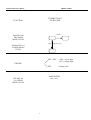
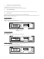
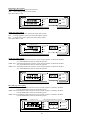
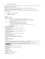
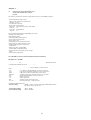
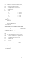
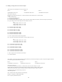
MICROVIP3 PLUS MENU
SHORT FORM
PUSHBUTTONS
TO BE USED
FUNCTION
PAGE
MOVING ON
THE SAME
MENU LEVEL
SEL
PAGE (3 sec.)
PASSAGE TO A
LOWER MENU
LEVEL
SEL + SET = SEL = select digit
SET = change digit
EDITING
SET
= change value
PAGE/ENTER
(for 3 sec.)
ESCAPE TO
AN UPPER
MENU LEVEL
I
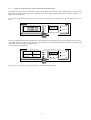
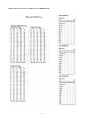
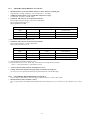
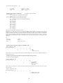
MICROVIP3 PLUS SET UP PAGES
SHORT FORM
PAG
SEt-UP
PAG
MEAS
SEL
PAG
SEL
12 pages of three-phase measurements
7 pages of single-phase measurements
Use SEL and
SET to select
baud rate (1200,
2400,4800,9600,
19200,38400),
data bits (7/8),
stop bits (1/2),
parity (no/e/o).
* Note 1: these 3 pages are present only when LOG off.
k
PAG
COM 9.60
n71
PAG
V
PAG
PAG
PAG
A
000100
P.t. 100
Std1
OPtion
000005
C.t. 1.00
SET
Use SEL and SET
to select PT primary
(from 1 to 999999 V)
and PT secondary
(57.7,63.5,100,110,115,
120,173,190,200,220 V),
CT primary (from 1 to
999999 A) and CT
secondary (from 0.01
to 1.00 V).
SET
m
Int 15
tiME
StAr
inSErt
SET
Std2
OPtion
SET
OPtion
PAG
dELtA
inSErt
SET
PAG
*
thd
50 Hz
SET
Use SET
to select
thd
1,2,5,10
60Hz
15,20,30,
60 minutes. SET
SET
SET
thd
Fnd 50 Hz
SET
Std1: kWh,kvarh
Std2: kWh,kVAh
COG: ±kWh,±kvarh
SET
thd
Fnd 60 Hz
PAG
*
m
LOG 01
rAtE
Std
LOG
SET
thd
OFF
2 PH
inSErt
COG4
PAG
SAMPLE
Use SEL
and SET
to select
from 1 to
99 minutes
of data
recording
rate.
00 = 3"
LOG
LOG no
CLEAr
SET
LOG YES
CLEAr
Press PAG
to clear
internal
memory;
display blinks
for 5"-10".
Std LOG = rms values
Sample LOG = V,I waveforms samples
Changing LOG type and confirming
by PAG., makes the display blinking
for 5" -10".
Fundamental frequency
selection: 50 Hz or 60 Hz;
OFF = no harmonic
measurements and printouts.
Fnd = thd referred to the fundamental
instead of rms value.
II
PAG
*
INDEX
1
1.1
1.2
1.3
1.4
USER SAFETY......................................................................................................................................... 1
INTRODUCTION..................................................................................................................................... 1
SAFETY PRECAUTIONS ...................................................................................................................... 1
SYMBOLS ................................................................................................................................................ 1
PRECAUTIONS IN CASE OF MALFUNCTIONING ........................................................................... 1
2
2.1
2.2
2.3
2.4
2.5
INTRODUCTION TO THE MICROVIP3 PLUS ................................................................................... 2
MAIN FEATURES .................................................................................................................................. 2
GREAT VERSATILITY.......................................................................................................................... 2
PURPOSE AND USE .............................................................................................................................. 2
DESCRIPTION OF THE INSTRUMENT .............................................................................................. 3
HANDLING THE INSTRUMENT ........................................................................................................ 4
3
3.1
3.1.1
3.2
3.2.1
3.2.2
3.2.3
3.3
3.3.1
3.3.2
3.4
3.4.1
3.4.2
INSTALLATION..................................................................................................................................... 6
PRELIMINARY INSPECTION .............................................................................................................. 6
KIT CONTENTS ..................................................................................................................................... 6
SAFETY INSTRUCTIONS ..................................................................................................................... 6
GROUNDING.......................................................................................................................................... 6
POWER REQUIREMENTS .................................................................................................................... 6
MAINS POWER FUSE ........................................................................................................................... 6
INSTRUMENT POWER ......................................................................................................................... 7
MAINS POWER ...................................................................................................................................... 7
BATTERY POWER................................................................................................................................. 7
MEASURING CONNECTIONS ............................................................................................................. 8
VOLTMETER CONNECTIONS............................................................................................................. 8
CURRENT MEASURING CONNECTIONS.......................................................................................... 8
4
4.1.1
4.1.2
4.1.3
4.2
4.3
4.4
4.4.1
4.4.2
4.4.3
OPERATION ........................................................................................................................................... 9
MEASURING THREE PHASE POWER (STAR SYSTEM) ................................................................ 9
MEASURING THREE PHASE POWER (DELTA SYSTEM)............................................................... 10
MEASURING TWO PHASE POWER.................................................................................................... 10
MEASURING SINGLE PHASE POWER (PHASE-NEUTRAL)........................................................... 11
AC/DC MEASUREMENTS .................................................................................................................... 11
SPECIAL CONNECTIONS..................................................................................................................... 12
CTs AND NON STANDARD CLAMP METER GRIPS ........................................................................ 12
THE INTA/1 AND INTA/5 INTERFACES ............................................................................................ 13
PTs............................................................................................................................................................ 14
5
5.1
5.1.1
5.1.2
5.2
5.2.1
5.2.2
5.2.3
5.3
5.3.1
5.3.2
5.4
MICROVIP3 PLUS OPERATING MODES ........................................................................................... 15
SINGLE PHASE MODE ......................................................................................................................... 15
THE PAGE KEY...................................................................................................................................... 15
ENERGY CONSUMPTION AND MAXIMUM DEMAND RESET ..................................................... 17
THREE PHASE MODE........................................................................................................................... 18
THE PAGE KEY...................................................................................................................................... 18
ENERGY CONSUMPTION AND MAXIMUM DEMAND RESET ..................................................... 21
THE SETUP PAGES MENU................................................................................................................... 22
PRINT FUNCTIONS ............................................................................................................................... 24
MANUAL PRINTING............................................................................................................................. 24
TIMED PRINTING.................................................................................................................................. 26
THE CALENDAR CLOCK ..................................................................................................................... 31
6
6.1
THE RS232C PORT ............................................................................................................................... 34
PC SOFTWARE...................................................................................................................................... 34
7
THE ON BOARD MEMORY................................................................................................................. 35
8
8.1
8.2
8.3
TECHNICAL SPECIFICATIONS.......................................................................................................... 35
GENERAL FEATURES ............................................................................................................................ 35
OPERATING CONDITIONS AND TESTING......................................................................................... 36
POWER REQUIREMENTS ...................................................................................................................... 36
III
8.3
8.4.1
8.4.2
8.5
8.5.1
8.6
8.6.1
8.6.2
8.6.3
8.7
8.8
8.9
PRIMARY MEASUREMENTS ................................................................................................................ 37
PRIMARY MEASUREMENTS ACCURACY ......................................................................................... 37
SECONDARY MEASUREMENTS ACCURACY ................................................................................... 38
DISPLAYED (AND PRINTED) VALUES ............................................................................................... 38
ADDITIONAL MEASUREMENTS OF THE PRINTER ......................................................................... 39
FORMULAE .............................................................................................................................................. 39
SINGLE-PHASE FORMULAE ................................................................................................................. 39
THREE-PHASE FORMULAE .................................................................................................................. 40
HARMONIC FORMULAE ....................................................................................................................... 40
PRINTER SPECIFICATIONS................................................................................................................... 40
CLAMP METER SPECIFICATIONS ....................................................................................................... 41
ON BOARD MEMORY SPECIFICATIONS............................................................................................ 41
9
9.1
OPERATION AND MAINTENANCE OF THE INSTRUMENT ............................................................ 41
CAUTIONS AND HINTS ......................................................................................................................... 41
ANNEX A
A.1
A.2
A.3
A.4
CHARACTERISTICS OF THE MICROVIP3 PLUS RS232C SERIAL
COMMUNICATION SOFTWARE PROTOCOL...................................................................................... 42
Q-BASIC EXAMPLE FOR MICROVIP3 PLUS READING .................................................................... 53
READING OF VOLTAGE AND CURRENT WAVEFORM SAMPLES................................................. 56
ON BOARD MEMORY DOWNLOADING .............................................................................................. 58
IV
1
USER SAFETY
− This instrument has been manufactured and tested to the standards laid down in IEC 1010-1 600V with regard to
category III installation and level of protection 2 under IEC 664-664A.
− It has left our factory in perfect working order.
− In order to maintain your instrument in perfect working order and to ensure safe operation, always follow the
instructions and notices given in this manual.
− Before connecting the instrument to the mains, check that the mains power and the instrument’s power requirements
correspond.
− Only connect the instrument to a grounded mains socket. Never use an extension lead without a ground wire.
− Plug in the main power plug before you switch on the measuring and control circuits.
Warning !
− Any breakage in the ground wire inside or outside the instrument, or the disconnection of the ground wire itself can
make the instrument dangerous to use. Do not interfere with the ground wire.
− During opening of covers or the removal of pieces, parts and connection points may also be live.
− Disconnect the instrument from the mains power source before starting any adjustment, maintenance, repair, or
replacement of components, and whenever the instrument has to be opened.
− Remember that capacitors inside the instrument may maintain their charge for a time even after the instrument has
been disconnected from the mains.
− Make sure that any replacement of safety devices are exactly the of right type and rated amperage. Never operate the
instrument with repaired safety devices or bypassed fuse holders.
− If it becomes clear that the instrument cannot be used in complete safety, remove it from service to prevent it being
used inadvertently.
− Safe operation cannot be guaranteed in the following cases :
− if the instrument is visibly damaged;
− if the instrument fails to operate correctly;
− if the instrument has been stored under unsuitable conditions for an extended period of time;
− if the instrument has been damaged during transit.
− Use only 80 mA T 250V fuses with 230VAC +/- 10% mains power.
− Use only 160 mA T 250V fuses with 110VAC +/- 10% mains power.
Read these pages carefully before installing
and using the instrument.
1.1 INTRODUCTION
The instrument described in this manual is intended for use by suitably trained personnel only.
Maintenance and repair operations involving the removal of the instrument cover must be carried out - exclusively - by
qualified and authorised staff.
1.2 SAFETY PRECAUTIONS
All personnel operating, servicing, or repairing the instrument must always follow standard safety procedures.
1.3 SYMBOLS
!
READ THE USER MANUAL !
1.4 PRECAUTIONS IN CASE OF MALFUNCTIONING
If you have reason to believe that the instrument may not be functioning as it should, for example if it has been
damaged in transit or in operation, remove it from service and make sure that no other persons can use it inadvertently.
Consign it immediately to authorised personnel for checking and repair.
1
2
INTRODUCTION TO THE MICROVIP3 PLUS
2.1
MAIN FEATURES
The MICROVIP3 PLUS is a low cost, class 1 (IEC1036) high technology portable analyzer for both single phase and
three phase systems, manufactured by ELCONTROL ENERGY and supplied complete with three 1000A clip-on CTs,
voltage leads and all accessories in strong carry case.
The MICROVIP3 PLUS is capable of performing 189 true effective value measurements on an unbalanced three phase
system starting from three voltage and three current measurements: 33 parameters are displayed on its crisp highcontrast back-lit LCD, 156 only on its built-in printer.
The instrument comes complete with a printer for manually controlled or automatic timed printout of all measurements,
as well as a calendar/clock for the display and printout of time and date.
The instrument can operate from 230 VAC Voltage supply (110VAC model is also available) or from internal
rechargeable batteries with an autonomy of over 7 hours provided no printing is performed and the display back-lit is
switched off.
A non-volatile flash 1 MB on-board memory provides data storage over extended survey periods including waveform
capture for current and voltage.
The MICROVIP3 PLUS is fitted with an RS232 port for connection to a Personal Computer for remote data control and
fast download via high-speed serial link.
The instrument has been designed for portable, mobile use in industrial environments.
2.2
GREAT VERSATILITY
The MICROVIP3 PLUS measures average three-phase and phase-neutral true rms voltage on all three phases, (max 600
Vrms), equivalent three phase current and true rms current per phase, total three phase power and power per phase, total
three-phase power factor and power factor per phase, reactive and apparent three phase system power, frequency, active
and reactive energy consumption/export, voltage and current total harmonic distortion per phase.
MICROVIP3 PLUS memorises energy consumption up to 999999 MWh and MVArh/MVAh and also memorises
active, reactive and apparent power peaks integrated using the technique of mobile averages over 1, 2, 5, 10, 15, 20, 30
or 60 minutes.
The basic model, supplied with three 1000A AC clamp meters, is capable of measuring power level from a minimum of
35W (5V, 7A) single phase to a maximum of 1,80MW (600V 1000A) three phase.
Optional AC clamp meters for up to 3000A and other DC models are also available.
All external CT/PT ratios, star/delta connection and power integration period are fully programmable.
The built-in 42 column graphic printer provides additional 156 parameters against manual print commands, and is
coupled to a calendar-clock to print out date and time along with measurements and to permit the generation of
automatically timed printed printouts at intervals of 1 to 99 minutes (with all measurements related to the printout start
time): data includes V & I harmonics to 24th multiple with both DC component and Displacement factor, and V & I
waveform/harmonic bar chart printout.
2.3
PURPOSE AND USE
The MICROVIP3 PLUS is intended for use by electrical power users who need to obtain an in-depth knowledge of their
plant and systems. It is also extremely useful for plant engineers, installers, maintenance engineers and electricians in
fault diagnosis and in the adjustment and repair of active electrical plant.
The MICROVIP3 PLUS enables you to:
−
−
−
−
−
−
−
−
−
Control loads and consumption;
Reduce overloads and power loss;
Check on the correct sizing of new plant entering service;
Prevent overheating and insulation problems;
Solve power factor correction problems;
Identify and eliminate load peaks and associated power problems;
Check 400 Hz naval plants and 600 Hz aeronautical plant;
Check uninterrupted power supplies with AC inputs and DC outputs;
Measure asymmetrical signal for PWM controllers.
2
2.4
DESCRIPTION OF THE INSTRUMENT
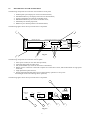
The following components are located on the instrument’s front panel:
1:
2:
3:
4:
5:
6:
backlit liquid crystal display for read-out of measurements;
PAGE/SEL/SET keys for display and control of measurements;;
liquid crystal display for read out of calendar-clock;
PRG/SELC/SETC keys for control of calendar-clock;
PAPER key for manual paper feed;
PRINT key for manual printout of all measurements;
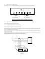
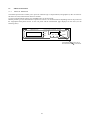
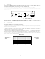
The following figure shows the layout of the above components.
1
3
MICROVIP3 PLUS
3-PHASE ENERGY & HARMONIC ANALYZER
PRINT
PAGE
6
PRG SELC SETC
SEL
PAPER
SET
5
ELCONTROL energy
Fig. 2.1
7
2
4
The following components are located on the rear panel:
1:
2:
3:
4:
mains power socket (for use with cable provided);
removable fuse-holder for safety fuse;
ON (I)/STANDBY (O) switch for activation of instrument;
RS232 port for connection to Personal Computer for remote data control, and fast download via high-speed
serial link;
5: single phase/three phase selector;
6: display backlight ON/OFF button (for use during battery operation to save power:
the backlight can be left on during mains operation).
The following figure shows the layout of the above components.
1
!
DISPLAY
LIGHT
3ø
RS232C
230V ±10%
50/60 Hz 4VA
I
FUSE
O
1ø
5
6
Fig. 2.2
3
80mA T 250V-
4
3
2
The following components are located on the top of the instrument:
1: connectors compartment with voltage and current measurement connectors;
2: printer.
The following figure shows the layout of these components.
1
2
Fig. 2.3
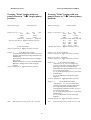
2.5
HANDLING THE INSTRUMENT
Adjustable Handle: the handle can be adjusted as required to support the instrument at the angle for display
readability.
Shoulder Strap Hooks: The shoulder strap provided with the kit can be used for carrying the instrument. The handle
has special holes into which the shoulder strap hooks can be inserted.
Shoulder strap
anchorage points
Printer Access: to open the printer compartment, simply press lightly on the ribbed section of the printer cover as
shown.
Printer compartment
Printer compartment
open
closed
4
Replacing the printer cartridge: open the printer compartment and press down on the area marked PUSH to remove
the old cartridge. Fit the new cartridge and push gently down into position.
PUSH
Replacing the printer roll: open the printer compartment and press down gently on the area marked PUSH to remove
the printer cartridge. Fit the paper toll and shown in the figure. Press the PAPER key repeatedly to feed the paper
through the mechanism. Replace the cartridge and check paper alignment.
Access to the volt and ampere measuring connectors: press on the ribbed area of the connectors compartment cover
on the top of the instrument (as for opening the printer compartment) and open it. The connector are located inside (see
figure). There are four single pole connectors for voltage measurements (N = neutral; L1 = R phase connection; L2 = S
phase connection; L3 = T phase connection) and 3 three pole connectors for the current measurement clamp meters (L1,
L2, L3).
Voltmeter and current
connection compartment
Press at ribbed areas
L1 L2 L3 N L1 L2 L3
5
3
INSTALLATION
3.1
PRELIMINARY INSPECTION
When you receive your MICROVIP3 PLUS, check that the kit is complete and that the instrument has not been
damaged in transit.
Refer to ELCONTROL ENERGY service network for any repair or replacement.
3.1.1
KIT CONTENTS
The instrument comes in a practical impact resistant case and with a number of accessories. The complete kit should
comprise:
1 MICROVIP3 PLUS instrument case
1 MICROVIP3 PLUS
1 power cable
1 set of voltage measuring cables
3 1000A/1Vrms AC clamp meters with cables
2 5X20 T 80 mA fuse (230VAC ± 10% power); T160 mA (110VAC± 10% power)
1 spare printer ribbon cartridge
1 spare printer paper roll
1 shoulder strap
1 instruction manual
1 guarantee certificate
1 calibration certificate
check that the kit is complete before starting to install the instrument.
3.2
SAFETY INSTRUCTIONS
3.2.1
GROUNDING
The MICROVIP3 PLUS instrument can be powered from the mains using the cable provided or from the internal
battery. When using the instrument under mains power, always connect up the power cable before making in measuring
connections, and make sure that the mains cable is plugged in to a grounded power socket.
Only use extension mains cables with suitable ground connections.
Use the internal battery only for shorter periods of operation.
3.2.2
POWER REQUIREMENTS
The instrument can operate from mains power of 230VAC±10% 50/60 Hz (a special version is available for use with
110VAC±10% 50/60 Hz).
3.2.3
MAINS POWER FUSE
With 230 VAC± 10% mains power only use 80 mA 250 V type T fuses of size 5X20.
With 110 VAC ± 10%mains power only use 160 mA 250 V type T fuses of size 5X20.
Always disconnect the instrument from the mains before replacing a fuse.
To replace a fuse, simply unscrew the fuse holder on the rear panel.
Make sure that replacement fuses are of the same type and rating as the one removed.
Do not use the instrument with repaired or short-circuited fuses.
6
3.3
INSTRUMENT POWER
3.3.1
MAINS POWER
The kit includes a power cable for connection to the mains supply.
Make sure that mains power is 230VAC ± 10% 50/60 Hz (or 110VAC ± 10% 50/60 Hz if your version is designed for
this rating).
Simply plug the mains cable into the socket at the rear of the instrument (see Fig. 3.1) and into the mains power outlet.
!
DISPLAY
LIGHT
3ø
RS232C
230V ± 10%
50/60 Hz 4VA
I
FUSE
O
1ø
80mA T 250V-
Fig. 3.1
Set the I/O switch to I to switch the instrument on.
The I/O switch only affects the instrument’s low tension circuits and battery output circuits (practically speaking, with
the switch set to I, the instrument operates normally; with the switch set to O, the instrument control circuits are
switched off but the battery charging circuit remains on).
With the instrument switched on, you can make the measuring connections required.
3.3.2
BATTERY POWER
The MICROVIP3 PLUS can also work by its internal rechargeable battery. The instrument automatically switches to
battery power as soon as the mains cable is disconnected.
The MICROVIP3 PLUS uses a Ni-Cd 6V 940 mAh battery (with five 1,2 V 940 mAh elements in series) giving the
instrument an autonomy of over seven hours providing no printouts are required and the display backlight is switched
off (the display backlight can be activated by pushing the button on the rear panel, and switches off after approximately
15 seconds from the moment the button is released).
Do not use battery power for long measuring operations or when extensive printing is needed.
The instrument warns of low battery level by displaying three flashing dots on the calendar-clock display. When battery
power is low, the instrument automatically disables the print function (see figure).
PRG
SELC
SETC
To restore printer functions, connect the instrument to the mains power at least until the third dot goes out (15 minutes
approx.).
If the battery is completely drained, for example after a long period in storage, the instrument may not switch on at all.
If it happens, simply connect the instrument to the mains to recharge the battery.
Leave the instrument switched off (standby) and connected to the mains for 24 hours to fully charge the battery.
IMPORTANT: no ground connection is needed when the instrument is working by battery:
DO NOT CONNECT THE INSTRUMENT TO GROUND.
7
3.4
MEASURING CONNECTIONS
The connectors for use in voltmeter and ammeter connections are located in the top of the instrument.
!
INPUT CURRENT
L1
L2
L3
N
INPUT VOLTAGE
L1
L2
L3
Connectors for
current measurements
Connectors for
voltage measurements
Follow these instructions carefully to avoid measurement errors.
3.4.1
VOLTMETER CONNECTIONS
Use the cables supplied for the purpose in the kit.
3.4.2
CURRENT MEASURING CONNECTIONS
Use the clamp meters supplied for the purpose in the kit.
When making current measurement make absolutely sure that each clamp meter is connected to the same phase
as the corresponding voltage measurement.
Incorrect connections can give rise to significant measuring errors since a phase angle between current and voltage of
120 degrees can be added.
When connecting the clamp meters with Std1 or Std2 option selected, you do not need to know the direction of flow
since the instrument automatically inverts in case of reversed connections.
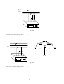
The following diagram (fig. 3.2) shows the correct connection layout.
(R) L1
(S) L2
LOAD
(T) L3
N
Fig. 3.2
8
4
OPERATION
4.1.1
MEASURING THREE PHASE POWER (STAR SYSTEM)
Set the connection type selector on the rear panel to 3 ø (THREE-PHASE) (see Fig. 4.1).
!
DISPLAY
LIGHT
3ø
RS232C
I
O
1ø
230V ± 10%
50/60 Hz 4VA
FUSE
80mA T 250V-
Fig. 4.1
Make all connections as shown Fig. 4.2.
(R) L1
(S) L2
LOAD
(T) L3
N
Fig. 4.2
If the neutral is unavailable it is possible to reconstruct it using the DSC-MT accessory (code 4AAC4) for voltages up
to 120VAC, DSC-400VAC (code 4AANY) for voltages up to 400VAC or DSCD2 (code 4AAHG) for voltages up to
700VAC. Make the necessary connections as shown in fig. 4.3.1
(R) L1
(S) L2
LOAD
(T) L3
DSC-MT
DSC-400VAC
DSCD2
Fig. 4.3.1
9
4.1.2
MEASURING THREE-PHASE POWER (DELTA SYSTEM)
(R) L1
(S) L2
(T) L3
Fig. 4.3.2
Connect L1, L2, L3; then connect the neutral voltage input to L3.
Note: Select Delta in Set-up Pages Menu
4.1.3
MEASURING TWO PHASE POWER
AC
N
ACC
Fig. 4.3.3
Connect L1 and L2; then connect the neutral Voltage input to L3.
Note : Select 2 PH in Set-up Pages Menu.
10
4.2
MEASURING SINGLE PHASE POWER (PHASE-NEUTRAL)
Set the connection type selector on the rear panel to 1ø (SINGLE-PHASE). Use only the instrument’s L1 phase inputs
(current to connector L1 and voltage between connectors L1 and N) as show in fig. 4.4.
(R) L1
LOAD
N
Fig. 4.4
4.3
AC / DC MEASUREMENTS
When taking measurements from DC circuits or networks, or circuits where alternating signals have direct components
superimposed (e.g. inverters, U.P.S., rectifiers), use the Hall effect clamp meters designed for these applications which
are available from the ELCONTROL ENERGY accessories catalogue. Use the ADAPTA-1V/1V adapter (code
4AACQ) for connections to the MICROVIP3 PLUS as shown in fig. 4.5 for the phase L1 inputs and in figs. 4.6 and 4.7
for three phase systems (taking care to ensure that voltage and current inputs correspond).
(R) L1
≅
(S) L2
LOAD
LOAD
(T) L3
ADAPTA-1V/1V
ADAPTA-1V/1V
Fig. 4.5
DSC-MT
DSC-400VAC
DSCD2
Fig. 4.6
When either option Std1 or Std2 is selected, the clamp meters can be connected in either direction since the
MICROVIP3 PLUS automatically inverts current direction if necessary.
11
4.4
SPECIAL CONNECTIONS
4.4.1
CTS AND NON-STANDARD CLAMP METERS
When using current transformers or current measuring clamp meters other than those supplied, use adapter interfaces
INTA/1 (code 4AABB) and INTA/5 (code 4AABD), as listed in the ELCONTROL catalogue.
1) Connect the CT secondary to the INTA/1 or INTA/5 interface.
2) Remove the short circuit from the CT.
3) Connect the interface to the instrument taking care that the voltage and current inputs
correspond.
CAUTION: always use the correct connection layout to avoid serious damage to the instrument (see Fig. 4.7).
(R) L1
(R) L1
(S) L2
(S) L2
(T) L3
LOAD
(R) L1
(S) L2
LOAD
(T) L3
LOAD
(T) L3
N
N
N
INTA/1
INTA/5
INTA/1
INTA/5
INTA/1
INTA/5
Fig. 4.7
When your measuring is finished:
1) Disconnect the interface from the instrument
2) Short circuit the CT secondary
3) Disconnect the CT secondary from the INTA/1 or INTA/5 interface
Fig. 4.8 shows example of CT and non standard clamp meter connections.
Make sure that you program the values of the CT primary as instructed in chapter 5 below.
(R) L1
(S) L2
LOAD
(T) L3
N
INTA/1-INTA/5
Fig. 4.8
12
4.4.2
THE INTA/1 AND INTA/5 INTERFACES
Note: one of the CT terminals is normally connected to a common ground (see fig. 4.9).
When using the INTA/1 and INTA/5 interfaces, bear in mind that there is no galvanic separation so that the
instrument’s ground is actually connected directly to the plant.
You must therefore make sure that there are no spurious voltages between the plant ground and the instrument’s
grounds and that no other conditions which could cause damage to the instrument exist
In these cases, use an insulating transformer (fig. 4.10), or three SEPA 5X1 interfaces (code 4AAER) available in the
ELCONTROL ENERGY accessories catalogue.
L1
L1
L2
L2
L3
L3
Fig. 4.9
L1
(R) L1
TA (uscita 5A)
(S) L2
(T) L3
N
TA 5/1
SEPA 5X1
INTA/1
Fig. 4.10
13
LOAD
4.4.3
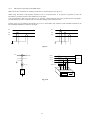
PTs
(R) L1
(S) L2
(T) L3
Connection to 2 voltage transformers
with one phase of the secondary grounded
DELTA
L1
L2
L3
N
Connection to 3 star voltage transformers with
one phase of the secondary grounded
DELTA
(R) L1
(S) L2
T) L3
N
Connection to 3 star voltage transformer
(PTs)
STAR
14
5
MICROVIP3 PLUS OPERATING MODES
The MICROVIP3 PLUS displays measurements on its LCD.
A switch on the rear panel allows you to select one of two operating modes.
5.1
SINGLE PHASE MODE
The instrument display and data control functions are controlled by the keys on the front panel shown in fig. 2.1.
5.1.1
THE PAGE KEY
The PAGE key enables you to switch the display between seven measurement pages.
When you switch the instrument on in single phase mode, the first measurement page is displayed by default. Press the
PAGE key to move on to the next pages.
First page (single-phase)
Volt: Rms phase-to-neutral voltage
Amp: Rms current
Watt: Active power with full scale value of VxA.
CosΦ P.F.: Power Factor with variations from -0,00 a +0,00.
MICROVIP3 Plus
3-PHASE ENERGY & HARMONIC ANALYZER
V
A
CosΦ
P.F.
PAGE
PRINT
SEL
KW
PRG
SELC SETC
PAPER
SET
ELCONTROL energy
Press page key to display
next pages
Second page (single-phase)
kVAr: Reactive power.
kVA: Apparent power.
Hertz: voltage Frequency, range 20 to 600 Hz (AC) and 00 Hz (DC).
MICROVIP3 Plus
VAr
3-PHASE ENERGY & HARMONIC ANALYZER
PRINT
PAGE
KVA
SEL
Hz
PRG
SELC SETC
PAPER
SET
ELCONTROL energy
Third page (single-phase)
kvarh (kVAh) : Reactive energy consumption for the single-phase system
(Apparent energy with STD2 option)
kWh : Active energy consumption for the single-phase system
MICROVIP3 Plus
3-PHASE ENERGY & HARMONICS ANALYZER
PAGE
PRINT
kVArh
SEL
KWh
SET
PRG
SEL
SET
ELCONTROL energy
15
PAPER
Fourth page (single-phase)
kVArh : Reactive energy export for the single phase system (COG4 option)
kWh : Active energy export (COG4 option)
MICROVIP3 Plus
3-PHASE ENERGY & HARMONIC ANALYZER
PAGE
kVArh
PRINT
SEL
PRG
SELC
SETC
PAPER
SET
ELCONTROL energy
Fifth page (single-phase)
kVAr : Average Reactive power peak of the single phase system
kVA : Average Apparent power peak of the single phase system
kW : Average Active power peak of the single phase system (Maximum demand)
Peak values are memorized and displayed only after an integration period of 1, 2, 5, 10, 15, 20, 30 or 60 minutes from
the time the instrument is first switched on. Values are updated every fifth of the integration period.
MICROVIP3 Plus
3-PHASE ENERGY & HARMONIC ANALYZER
PAGE
kVA
kVAr
PRINT
SEL
W
PRG
PEAK MEM
SELC
SETC
PAPER
SET
ELCONTROL energy
Sixth page (single-phase)
THDF V - THDF A : Total Harmonic Distortion Factor of Voltage and Current referenced
to the rms or to the fundamental value for the 50/60 Hz systems
MICROVIP3 Plus
V
3-PHASE ENERGY & HARMONIC ANALYZER
A
PAGE
PRINT
SEL
PRG
SELC
SETC
PAPER
SET
ELCONTROL energy
Seventh page (single-phase)
Data storage control page
Log on (off) : to activate (or de-activate) data storage (using the SET key)
01-99 m (minutes) : Data records rate
(00 = 3 seconds)
00-100 (%) MEM : % of memory used
MICROVIP3 Plus
3-PHASE ENERGY & HARMONIC ANALYZER
m
PAGE
PRINT
SEL
PRG
MEM
SELC
SETC
SET
ELCONTROL energy
16
PAPER
5.1.2
ENERGY CONSUMPTION AND MAXIMUM DEMAND RESET
The SET button resets to zero all electrical energy consumption counts (kVArh, kVAh, kWh) and active, reactive and
apparent power peak values. The button is enabled only when the page displayed reads out one of these values (i.e. in
pages three, four and five).
If you press the SET button while page three or page four is displayed, the energy counts on the display are reset to
zero.
MICROVIP3 Plus
3-PHASE & HARMONIC ANALYZER
PAGE
kVArh
kWh
PRINT
SEL
PRG
SELC SETC
PAPER
SET
ELCONTROL energy
If you press the SET button while the fifth page is displayed, the active and reactive power peak values are reset to zero.
The buffer used to calculate average power is also cleared, and this measurement therefore remains invalid until the
programmed integration time has elapsed again.
A series of dashes is displayed.
MICROVIP3 Plus
VAr
3-PHASE ENERGY & HARMONIC ANALYZER
VA
PAGE
PRINT
SEL
W
PRG
PEAK MEM
SELC SETC
SET
ELCONTROL energy
Once you have reset values, press the PAGE key to return to measuring mode.
17
PAPER
5.2
THREE PHASE MODE
The instrument display and data control functions are controlled by the keys on the front panel. The following keys
control the display of measurements:
5.2.1
THE PAGE KEY
The PAGE key allows you to display each of 12 measurement pages.
When you switch on the instrument on in three phase mode, the first measurement page is displayed by default.
Press the PAGE key repeatedly to move on the other pages.
First page (three-phase)
Volt: Rms phase to phase voltage of three phase system (average of the three-phase system).
Amp.: Rms current equivalent to a symmetrical and balanced three phase system .
P.F. Cosø : Power factor of the three phase system.
kWatt : Active power of the three-phase system.
MICROVIP3 Plus
3-PHASE ENERGY & HARMONIC ANALYZER
V
A
Cosø
P.F.
PAGE
PRINT
SEL
kW
PRG
3ø
SELC
SETC
PAPER
SET
ELCONTROL energy
Second page ( three-phase)
Volt L1: Rms voltage between phase L1 and neutral (STAR)
Rms voltage between L1 and L3 (DELTA)
Volt L2: Rms voltage between phase L2 and neutral (STAR)
Rms voltage between L2 and L3 (DELTA)
Volt L3: Rms voltage between phase L3 and neutral(STAR)
Rms voltage between L1 and L2 (DELTA)
MICROVIP3 Plus
V
3-PHASE ENERGY & HARMONIC ANALYZER
L2
L1
PAGE
PRINT
SEL
L3
PRG
SELC
SETC
PAPER
SET
ELCONTROL energy
Third page (three-phase)
Amp L1: Rms Current of Phase1.
Amp L2 : Rms Current of Phase2.
Amp L3 : Rms Current of Phase3.
MICROVIP3 Plus
L1
3-PHASE ENERGY & HARMONIC ANALYZER
L2 A
PAGE
PRINT
SEL
L3
PRG
SELC
SETC
SET
ELCONTROL energy
18
PAPER
Fourth page (three phase)
kW L1 : Phase L1 active power.
kW L2 : Phase L2 active power.
kW L3 : Phase L3 active power.
(kW L3 only in three-phase, STAR; missing in DELTA)
MICROVIP3 Plus
L1
3-PHASE ENERGY & HARMONIC ANALYZER
L2
L3
PAGE
PRINT
SEL
kW
PRG
SELC
SETC
PAPER
SET
ELCONTROL energy
Fifth page (three-phase)
P.F. Cosø L1 : Phase L1 power factor
P.F. Cosø L2 : Phase L2 power factor
P.F. Cosø L3 : Phase L3 power factor
(only in three-phase, STAR; missing in DELTA)
MICROVIP3 Plus
L1
3-PHASE ENERGY & HARMONIC ANALYZER
L2
PAGE
PRINT
SEL
Cosø L3
P.F.
PRG
SELC
SETC
PAPER
SET
ELCONTROL energy
Sixth page (three-phase)
kVAr : Reactive power of the three phase system
kVA : Apparent power of the three phase system
Hz : Voltage frequency
MICROVIP3 Plus
kVAr
3-PHASE ENERGY & HARMONIC ANALYZER
PAGE
kVA
PRINT
SEL
PRG
Hz
3ø
SELC
SETC
PAPER
SET
ELCONTROL energy
Seventh page (three-phase)
kVArh : Reactive energy consumption for the three phase system (Apparent energy with STD2 option)
kWh : Active energy consumption for the three phase system
Note: Press SET to clear
MICROVIP3 Plus
3-PHASE ENERGY & HARMONIC ANALYZER
PAGE
kVArh
PRINT
SEL
kWh
PRG
3ø
SELC
SETC
SET
ELCONTROL energy
19
PAPER
Eighth page (three-phase)
kVArh : Reactive energy export (COG4 option)
kWh : Active energy export (COG4 option)
Note: Press SET to clear
MICROVIP3 Plus
3-PHASE ENERGY & HARMONIC ANALYZER
PAGE
kVArh
PRINT
SEL
kWh
PRG
3ø
SELC
SETC
PAPER
SET
ELCONTROL energy
Ninth page (three-phase)
kVAr : Average reactive power peak of the three phase system
kVA : Average apparent power peak of the three phase system
kW : Average active power peak of the three phase system
Note: Press SET to clear
MICROVIP3 Plus
3-PHASE ENERGY & HARMONIC ANALYZER
PAGE
kVAr
PRINT
kVA
SEL
kW
PEAK MEM
PRG
3ø
SELC
SETC
PAPER
SET
ELCONTROL energy
Tenth page (three-phase)
THDF VL1 : Total harmonic distortion factor of the voltage of phase 1 referred to the Rms
or to the fundamental value for 50/60 Hz systems
THDF VL2 : Total harmonic distortion factor of the voltage of phase 2 referred to the Rms
or to the fundamental value for 50/60 Hz systems
THDF VL3 : Total harmonic distortion factor of the voltage of phase 3 referred to the Rms
or to the fundamental value for 50/60 Hz systems
MICROVIP3 Plus
V L1
3-PHASE ENERGY & HARMONIC ANALYZER
L2
PAGE
PRINT
SEL
L3
PRG
SELC
SETC
PAPER
SET
ELCONTROL energy
Eleventh page (three-phase)
THDF AL1: Total harmonic distortion factor of the current of phase 1 referred to the Rms
or to the fundamental value for 50/60 Hz systems
THDF AL2: Total harmonic distortion factor of the current of phase 1 referred to the Rms
or to the fundamental value for 50/60 Hz systems
THDF AL3: Total harmonic distortion factor of the current of phase 1 referred to the Rms
or to the fundamental value for 50/60 Hz systems
MICROVIP3 Plus
L1
3-PHASE ENERGY & HARMONIC ANALYZER
L2 A
PAGE
PRINT
SEL
L3
PRG
SELC
SETC
SET
ELCONTROL energy
20
PAPER
Twelfth page (three-phase)
Data storage control page.
LOG on (off) : To activate (or de-activate) storage (using the SET key)
01 - 99 m (minutes) : Data recording rate
(00 = 3 seconds)
00 - 100 (% mem) : % of memory used
MICROVIP3 Plus
3-PHASE ENERGY & HARMONIC ANALYZER
m
PAGE
PRINT
SEL
PRG
MEM
SELC
SETC
PAPER
SET
ELCONTROL energy
5.2.2
ENERGY CONSUMPTION AND MAXIMUM DEMAND RESET
The SET button resets to zero the electrical energy consumption counts (KVArh, KVArh and kWh) and the average
three phase active, reactive and apparent power peak values.
This function of the SET button is enabled only while the seventh, eighth or ninth measurement page is displayed (i.e.
where these values appear).
If you press the SET button while the seventh or eight measurement page is displayed, the energy consumption meters
are reset to zero.
MICROVIP3 Plus
3-PHASE & HARMONIC ANALYZER
PAGE
kVArh
kWh
PRINT
SEL
PRG
3ø
SELC SETC
PAPER
SET
ELCONTROL energy
If you press the SET button while the ninth measurement page is displayed, the peak values for average three-phase
active, reactive and apparent power are reset to zero.
The buffer used for calculating average power is also reset, so that this value remains invalid until the programmed
integration time has lapsed again.
A series of dashes is displayed.
MICROVIP3 Plus
3-PHASE ENERGY & HARMONIC ANALYZER
kVA
kVAr
PAGE
PRINT
SEL
kW
PRG
3ø
SELC SETC
SET
ELCONTROL energy
Once you have reset values, press the PAGE key to return to measuring mode.
21
PAPER
5.2.3
SETUP PAGES MENU
To access this menu, press the SEL key. To exit from this menu,
press the PAGE key for 3 seconds. To change the page, press the
PAGE key.
SEt - UP
First page
V
Use SEL and SET to select PT primary (from 1 to 999999V) and
PT secondary ( 57.7, 63.5, 100, 110, 115, 120, 173, 190, 220V).
Factory default : 100V/100V
000100
P.t. 100
Second page
Use SEL and SET to select CT primary (from 1 to 999999 A) and
CT secondary (from 0.01 to 1.00V).
Factory default : 1000A/1V
A
000005
C.t. 1.00
Third page
Press the SET key to preset the instrument for Standard 1 (kWh,
kVArh), Standard 2 (kWh, kVAh) or COG4 (± kWh, ± kVArh)
energy meters.
Factory default : Std1
Std1
Std2
COG 4
Fourth page
Press the SET key to preset the instrument for three-phase StAr
systems, three-phase DELTA systems or two phase (2 PH) systems.
Note: Delta selection forces COG4 mode and third page is hidden.
StAr
InSErt
dEltA
inSErt
2 PH
inSErt
Fifth page
m
Int 15
time
Use the SET key to select a 1, 2, 5, 10, 15, 20, 30 or 60 minutes
integration time.
Factory default : 15 minutes
22
Sixth page
Use the SET key to select a 50 Hz or a 60 Hz fundamental frequency
OFF = no harmonic measurements and printouts
Fnd = thd referred to the fundamental instead of rms value
Factory default : OFF
thd
50 Hz
thd
60 Hz
thd
OFF
thd
Fnd 50 Hz
Seventh page
thd
Fnd 60 Hz
This page is present only when LOG is OFF
Std
LOG
SAMPLE
LOG
Use the SET key to change the LOG type and confirm using PAGE
key : the display will blink for 5-10 seconds.
Standard LOG = rms values are stored
Sample LOG = V, I waveforms samples are stored
Factory default : Std
NOTE : changing the LOG type clears the on-board memory.
Eighth page
This page is present only when LOG is OFF
LOG
rate
m
01
Use SEL and SET keys to select from 1 to 99 minutes of data
recording rate.
00 = 3 seconds
Factory default : 1 minute
Ninth page
This page is present only when LOG is OFF
LOG
CLEAR
no
Use the SET key to select NO/YES; press the PAGE key to clear
internal memory : the display will blink for 5-10 seconds
Factory default : NO
LOG
YES
CLEAR
Tenth page
COM
k
9,60
n 71
Use SEL and SET keys to select baud rate (1200, 2400, 4800, 9600,
19200 or 38400 baud), data bits (7/8), stop bits (1/2), parity
(no/even/odd)
Factory default : 9600, 7, 1, n
23
5.3
PRINT FUNCTIONS
5.3.1
MANUAL PRINTING
The manual print function enables you to print out numerical (up to 189 parameters) and graphical (V & I waveform or
harmonic bar chart) measurements whenever needed.
To print out measurements simply press the PRINT key on the front panel.
Manual printouts give the date and time of printout as well as a list of measurements depending both on the position of
the single-phase/three-phase selector on the rear panel and the measurement page displayed on the LCD (see the
following table).
MICROVIP3 Plus
3-PHASE ENERGY & HARMONIC ANALYZER
PAGE
SEL
PRINT
PRG SELC SETC
SET
PAPER
ELCONTROL Energy
Press PRINT key to print out all
measurements taken by instrument
24
MICROVIP3 PLUS
MANUAL PRINTOUT FORMAT
Pressing "Print" button with rear
panel selector in "1-Φ
Φ" (single-phase)
position:
Pressing "Print" button with rear
panel selector in "3-Φ
Φ" (three-phase)
position:
Measurement page
Measurement page
Printout format
In Pg.1,2,3,4,5,7 → V
A
P.F.
kW
kVA
kVAr
Hz
+ kWh
+ kvarh
- kWh
- kvarh
Peak kVAr
Peak kVA
Peak kW
(Format equivalent to Type 0 automatic printout)
Printout format
In Pg.1,4,5,6,7,8,9,12 → V
A
P.F.
kW
kVA kVAr
Hz
+ kWh
+ kvarh
- kWh
- kvarh
Peak kVAr Peak kVA Peak kW
VL1
VL2
VL3
AL1
AL2
AL3
kW1
kW2
kW3
P.F.1
P.F.2
P.F.3
(Format equivalent to Type 0 automatic printout)
plus
V and I waveforms
(Format equivalent to Type 1 automatic printout)
In Pg.6 →
1-24th Harmonics and DC
component of Voltage and Current expressed as
absolute value and in percentage referred to the
fundamental;
Total Harmonic Distortion Factors of Voltage
and Current;
Displacement Factor (Cosø of the fundamental);
Harmonics Voltage and Current bar-graph
diagram
(Format equivalent to Type 2 automatic printout)
In Pg.2 → V1,V2,V3 waveforms
(Format equivalent to Type 1 automatic printout)
In Pg.3 → I1, I2, I3 waveforms
(Format equivalent to Type 3 automatic printout)
In Pg.10 →
1-24 th Harmonics and DC
component of L1, L2, L3 Voltages and
Currents expressed as absolute value and in
percentage referred to the fundamental;
Total Harmonics Distortion Factors of L1, L2,
L3 Voltages and Currents ;
L1, L2, L3 Displacement Factors (Cosø of the
fundamental) ;
L1, L2, L3 Harmonic Voltages bar-graph
diagrams
(Format equivalent to Type 2 automatic printout)
In Pg.11 →
1-24 th Harmonics and DC
component of L1, L2, L3 Voltages and
Currents expressed as absolute value and in
percentage referred to the fundamental;
Total Harmonic Distortion Factors of L1, L2,
L3 Voltages and Currents;
L1, L2, L3 Displacement Factors (Cosø of the
fundamental);
L1, L2, L3 Harmonic Currents bar-graph
diagrams
(Format equivalent to Type 4 automatic printout)
Note:
Stop Printout pressing "Print" for 5 seconds.
Note:
25
Stop Printout pressing "Print" for 5 seconds.
5.3.2
TIMED PRINTING
This function enables you to specify a time interval at which the instrument automatically prints out up-to-date
measurements and graphs.
The timed printout interval and the Automatic Printout type are programmed using the calendar-clock (see 5.4 ).
Timed printouts formats are the same than in manual printing but without the indication " Manual "
in the first row.
26
MICROVIP3 PLUS MANUAL PRINTOUTS: SINGLE-PHASE
TYPE 2 (1-ø ) corrsponding to :
see Manual Printout Format pg. 25
TYPE 0 (1-ø ) corresponding to :
see Manual Printout Format pg. 25
TYPE 1 (1-ø ) corresponding to :
see Manual Printout Format pg. 25
27
MICROVIP3 PLUS MANUAL PRINTOUTS: THREE-PHASE
TYPE 1 (3-ø) corresponding to :
see Manual Printout Format pg. 25
TYPE 0 (3-ø) corresponding to :
see Manual Printout Format pg. 25
28
TYPE 3 (3-ø) corresponding to :
see Manual Printout Format pg. 25
MICROVIP3 PLUS MANUAL PRINTOUTS: THREE-PHASE
TYPE 2 (3-ø) corresponding to :
see Manual Printout Format pg. 25
29
MICROVIP3 PLUS MANUAL PRINTOUTS: THREE-PHASE
TYPE 4 (3-ø) corresponding to :
see Manual Printout Format pg. 25
30
5.4
THE CALENDAR CLOCK
The instrument's calendar clock displays TIME, DAY, MONTH, and YEAR on an LCD on the front panel. The clock
also allows to program the type and the intervals for timed (automatic) printouts. You can use the PRG, SELC and
SETC buttons underneath the clock display to control clock funtions.
• Normal clock mode:
When the instrument is switched on, the clock displays the HOUR and MINUTES.
Press the SELC button to display DAY and MONTH, and press again to display the YEAR. (The clock automatically
returns to the hour and minutes display after 20 seconds.)
HOUR
12
PRG
MINUTES
:
SELC
DAY
35
MONTH
25
SETC
PRG
YEAR
11
SELC
SETC
99
PRG
SELC
SETC
• Programming Timed Printouts:
The MICROVIP3 PLUS allows you to program the type of automatic printout and the interval at which automatic
printouts are generated. (Any interval from 1 to 99 minutes can be set).
Press the PRG button to enter clock programming mode (see figure).
t
PRG
0
SELC
SETC
A "t" (type) and a zero are displayed initially. Using SETC button, select the type of automatic printout, depending on
the position of the single-phase/three-phase selector on the rear panel (see the following table).
31
MICROVIP3 PLUS
TIMED PRINTOUT FORMAT
Rear panel selector in
"1-Φ" (single-phase) position.
Rear panel selector in
"3-Φ" (three-phase) position.
type
type
Automatic Printout type
0=
V
A
P.F.
kW
kVA
kVAr
Hz
+ kWh
+ kvarh
- kWh
- kvarh
Peak kVAr
Peak kVA
Peak kW
0=
(Typical printing time = 1 minute)
Automatic Printout type
V
kVA
+ kWh
- kWh
Peak kVAr
VL1
AL1
kW1
P.F.1
A
kVAr
P.F.
kW
Hz
+ kvarh
- kvarh
Peak kVA Peak kW
VL2
VL3
AL2
AL3
kW2
kW3
P.F.2
P.F.3
(Typical printing time = 1 minute)
1
=
V, I waveforms
(Typical printing time = 3 minutes )
1=
V1, V2, V3 waveforms
(Typical printing time = 3 minutes )
3=
I 1, I2, I3 waveforms
(Typical printing time = 3 minutes )
2=
1-24th Harmonics and DC component
of Voltage and Current expressed as absolute
value and in percentage referred to the
fundamental;
Total Harmonic Distortion Factors of Voltage
and Current;
Displacement Factor (Cosø of the fundamental);
Harmonics Voltage and Current bar-graph
diagram ;
2=
1-24 th Harmonics and DC component of
L1, L2, L3 Voltages and Currents expressed as
absolute value and in percentage referred to the
fundamental;
Total Harmonics Distortion Factors of L1, L2,
L3 Voltages and Currents ;
L1, L2, L3 Displacement Factors (Cosø of the
fundamental) ;
L1, L2, L3 Harmonic Voltages bar-graph
diagrams ;
(Typical printing time = 5 minutes)
(Typical printing time = 5 minutes)
4=
Note: printing time depends on battery charge
.
1-24 th Harmonics and DC component of
L1, L2, L3 Voltages and Currents expressed as
absolute value and in percentage referred to the
fundamental;
Total Harmonic Distortion Factors of L1, L2,
L3 Voltages and Currents;
L1, L2, L3 Displacement Factors (Cosø of the
fundamental);
L1, L2, L3 Harmonic Currents bar-graph
diagrams ;
(Typical printing time = 5 minutes)
32
Press the PRG button to enter Printing Interval selection page.
A "P" and two zeros are displayed initially. These represent the tens and units of the printing interval.
Simply set the number of minutes you require for the interval between one printout and the next.
P
0 0
PRG
SELC
SETC
Press the SELC button to switch between the tens and the units. The digit currently programmable flashes.
Press the SETC button repeatedly to set the value you require for each digit. Once you have set the require value, press
the PRG button again to enter clock set up page.
P
4 1
PRG
SELC
SETC
To disable automatic timed printouts, set the print interval to 00.
• CLOCK SET UP:
The initial display shows two zeroes. This is for the YEAR value.
y
0 0
PRG
SELC
SETC
Press PRG button twice
Use the SELC button to select the tens and units and press the SETC button to set the required value, and set the current
YEAR value
When a new year is set, the month and day values are automatically reset to 1.
Press the PRG button to move on the next display in which you can set DAY and MONTH.
Use the SELC button to select the month or day value, and the SETC button to set the correct date.
0 1
PRG
0 1
SELC
SETC
If you set a new month, the day value is automatically reset to 1.
The calendar clock performs a check on the values input to check for incongruities.
Press the PRG button to move on the next setup page in which you can set the HOUR and MINUTES.
Proceed as before to set the hour and minutes. On completion of the clock setup, press the PRG button again to return
normal clock mode.
33
6
RS232 PORT
The rear panel the MICROVIP3 PLUS is fitted with a mini-Canon 9 pin connector for use with a RS232C cable in the
transmission of measurement data or V & I waveforms from the instrument to a PC.
This enables measurement data and instrument setup to be controlled from a remote personal computer.
1200, 2400, 4800, 9600, 19200, 38400 baud, 7/8 data bits, 1/2 stop bits, no/even/odd parity are selectable. (For data
format see Annex A)
!
DISPLAY
LIGHT
3ø
RS232C
230V ∼± 10%
50/60 Hz 4VA
I
FUSE
O.F.
O
1ø
80mA T 250V-
RS232C CONNECTOR
Note : By means of a PC-485-BOX (code 4AAK4)/PC-485-BOARD (code 4AAK1) it is possible to connect a
MICROVIP3 PLUS to a RS485 monitoring network: its address is fixed to 1.
6.1
PC SOFTWARE
ELCONTROL ENERGY PC softwares for data acquisition are :
- VIPVIEW (code 4AAGW) - Win95/98 general purpose software for supervision, control and energy data acquisition
for RS485 serial networks VIPNET-485
- VIPLINK (code 4AAL3) - VIPLOAD (code 4AAO3) - Simple DOS software for reading, storage and printout of
energy measurements for RS485 serial networks VIPNET-485
- MicroWin - Win95/98 and NT4.0 powerful software for stand-alone instruments. It provides features like manual &
automatic measurements campaign, downloading of 1MB on board memory via high-speed serial link (38400 baud), V
& I harmonic analysis to 24th multiple with both DC component and displacement factor, V & I waveforms display and
printout, harmonic bar-chart display and printout.
RS232 CABLE
MICROVIP3 PLUS
9 PIN CANON
MALE
PIN
1
2
3
4
5
6
7
8
9
FUNZIONE
N.C.
RX
TX
TX
RX
N.C.
GND
GND
N.C.
N.C.
N.C.
N.C.
34
PIN
N.C.
3
2
N.C.
5
N.C.
N.C.
N.C.
N.C.
PC
9 PIN CANON
FEMALE
7
THE ON BOARD MEMORY
The on board memory is a 1 Mbyte non-volatile flash memory for data storage over extended surveys periods including
waveform capture for current and voltage.
Two different LOG types are selectable:
- In Standard LOG, Max 7840 records of all the measurements are available after a memory reset.
- In Sample LOG, Max 677 records of all Voltages and Currents waveforms are available after a memory reset.
Data recording rate is selectable from 1 to 99 minutes.
Fast data downloading to PC is provided via a high-speed RS232C serial link and based on WIN 95/98 and NT 4.0
software MicroWin.
8
TECHNICAL SPECIFICATIONS
8.1
GENERAL FEATURES
• Inputs:
L1, L2, L3, N, I1, I2, I3.
• Input specifications:
Voltage:
(L1-N, L2-N, L3-N) direct inputs max 600 Vrms (STAR);
(L1-L3, L2-L3, L1-L2) direct inputs max 600 Vrms (DELTA) from 0 to 600 Hz;
up to 999999 V (with external PTs whose primary and secondary are selectable).
Input impedance: 4 MΩ
Current:
(I1, I2, I3) direct inputs 1 Vrms up to 600 Hz, or 1 VDC;
1000A from 30 to 600 Hz (with standard AC clamp meters);
from 0 to 600 Hz (with optional AC/DC clamp meters);
up to 999999 A (with external CTs whose primary and secondary are selectable).
Input impedance: 10 kΩ
• Voltmeter input overload:
maximum acceptable voltage 625 Vrms, peak voltage 825V.
• Current input overload:
5 times full scale value (with protection trip at threshold value).
• Units of measurement:
m, k, M, W, V, A, VA, Var, Hz, Wh, VArh, VAh, P.F. Cosø, THDF.
• Measurement frequency:
1,2 seconds without harmonics - 2,5 seconds with harmonics.
• Number of scales:
3 voltage scales; 3 current scales with automatic scale change.
• Automatic scale change:
Scale change response time: 1,2 secs
Change to higher scale takes place at 105% active scale.
Change to lower scale takes place at 20% of active scale.
• Clock:
Quartz, output to LCD
Printed date and time output.
• Batteries:
One Ni-Cd 6V 940mAh battery of five 1,2V 940mAh elements in series, giving autonomy of approximately 7 hours
without printing and display backlight. Battery recharge time: 24 hours (from mains).
One 3,5V 280mAh lithium battery as memory buffer (guaranteeing memory backup for approximately 7 years).
IMPORTANT: when the lithium back-up battery is changed, date and time are lost.
Battery replacement must be carried out by qualified, authorized staff at ELCONTROL ENERGY service centres.
• Measurement display:
Backlight LCD with temperature range of -30°C to +80°C.
• Clock display:
4 digit LCD with temperature range of -10°C to +60°C.
• Dimensions:
251 x 239 x 104 mm.
• Instrument weight:
2,9 Kg.
• Weight of MICROVIP3 PLUS KIT:
6,3 Kg.
• Degree of protection : IP 40
35
8.2
OPERATING CONDITIONS AND TESTING
• Environmental operating conditions:
Environmental temperature range: from -10°C to +50°C.
Relative humidity (R.H.): from 20% to 80%.
• Storage temperature:
from -20°C to +60°C.
• Condensation:
non-condensing environment.
• Insulation resistance:
≥ 500 MΩ between voltmeter input connectors short-circuited between each other and instrument frame, between
power socket and instrument frame.
≥ 2 MΩ between voltage and current inputs.
• Insulation voltage:
Tested to 2000 Vrms at 50 Hz for 60 seconds between voltmeter input connections (including neutral).
Tested to 3000 Vrms for 60 seconds between each connector and the instrument frame.
• Construction standards:
Safety : IEC 1010-1, EN 61010-1, 600V cat. III
EMC : EN 50081-1, EN 50082-1, EN55022.
IEC 801-2, ENV50140 IEC 801-3, IEC 801-4
Conformity : CEE 89/336 (EMC)
CEE 73/23 - CEE 93/68 (Low Voltage Directive)
8.3
POWER REQUIREMENTS
• External mains power:
230V ∼ ± 10% 50/60 Hz or 110V ∼ ± 10% 50/60 Hz
• Consumption:
4 VA.
• Internal battery power:
6V 940mAh N1-Cd battery with five 1,2V 940mAh elements in series.
8.4
PRIMARY MEASUREMENTS
• Measuring method:
fixed sampling, A/D conversion.
• Sampling frequency:
2,5 KHz.
• Number of samples per phase:
250 (100 msec).
• Measuring frequency:
~ 1,2 sec.
• Automatic zero regulation:
every 1 minute.
36
8.4.1
PRIMARY MEASUREMENT ACCURACY
• Measurement error in environment of 18°°C to 25°°C (after 10’ warming up):
expressed as ± % Rdg. (reading) + % F.S. (Full Scale) – see tables.
• Additional measurement error outside this temperature range:
± 0,02% F.S. for each °C outside range.
• Sensitivity and accuracy of voltage measurements:
Direct input with max voltage = 750 Vrms at Full Scale.
Input voltage peak factor ≥ 1,6.
Input impedance ≥ 4 MΩ.
Rated
range
37 Vrms
174 Vrms
750 Vrms
Sensitivity, Full Scale and voltage accuracy
Sensitivity
Full Scale
24 mV*
111 mV
480 mV
37,0 V
174 V
750 V
ε between 20% F.S.
and 100% F.S.
0,5%F.S.+ 0,5%Rdg.
0,3%F.S.+ 0,3%Rdg.
0,3%F.S.+ 0,3%Rdg.
(*) the minimum measurable signal is 1 V.
• Sensitivity and accuracy of current measurement:
Direct input with max. 1 Vrms at Full Scale.
Input current peak factor ≥ 1,6
Rated
range
50 mV
232 mV
1V
Sensitivity, Full Scale and current accuracy
Sensitivity
Full
ε between 20%F.S
Scale**
and 100%F.S.
*
50 mV
0,5%F.S.+ 0,5%Rdg.
32 µV
232 mV
0,3%F.S.+ 0,3%Rdg.
140 µV
1V
0,3%F.S.+ 0,3%Rdg.
640 µV
(*) the minimum measurable signal is 2 mV.
(**) Full Scales for 50,0 - 232 - 1000 Amp. with 1000 A/1V clamp meters provided
(Error = sum of instrument + clamp meter errors).
• Accuracy does not take account of clamp meter error.
• Voltage and current measurement precision as a function of frequency:
no error over errors specified in tables for signal frequencies in 20-90 Hz range.
8.4.2
SECONDARY MEASUREMENTS ACCURACY:
Power (single or three phase), Active Energy (and Power Factor) : class 1 (IEC 1036)
• Measurement of other secondary values:
error is expressed by the formula which defines the value (sections 8.6.1, 8.6.2 and 8.6.3), as a function of V, I and
W.
37
L1
L2
L3
38
Cosø fnd
VH24, AH24
VH23, AH23
VH22, AH22
VH21, AH21
VH20, AH20
VH19, AH19
VH18, AH18
VH17, AH17
VH16, AH16
VH15, AH15
VH14, AH14
VH13, AH13
VH12, AH12
VH11, AH11
VH10,AH10
VH9, AH9
VH8, AH8
VH7, AH7
VH6, AH6
VH5, AH5
VH4, AH4
VH0, AH3
VH2, AH2
8.5.1
VH1, AH1
VH0, AH0
Time
Date
±kvarh
±kWh
kvarh
kVAh
kWh
Hz
THDFI
THDFV
kW Peak
(MD)
kVA Peak
kvar Peak
P.F.
Var
VA
Watt
Ampere
Volt
8.5
DISPLAYED AND PRINTED VALUES
L1
L2
L3
3ø
ADDITIONAL MEASUREMENTS OF THE PRINTER
8. 6
FORMULAE
8.6.1
SINGLE PHASE FORMULAE
n
V1N =
True rms voltage
W1 =
Active power
1
∑(
n
1
1
n
n
∑ (v1N)
1
i
Power factor
P. F. = W1 / VA1
True rms current
A1 =
Apparent power
VA1 = V1N . A1
Reactive power
VAr =
where
(v1N)i
1
n
1 n
∑
n 1
v1N)²
i
. (a1)
i
n
∑ (a1)²
1
i
(v1n ). (a1)
i
i+ j
(a1)i : samples of voltage and current
j : number of samples corresponding to 90° electrical degrees
8.6.2
THREE PHASE FORMULAE
Equivalent three phase voltage
V∑ = (V1N + V2N + V3N) / 3
(Star)
V∑ = (V12 + V23 + V31) / 3
(Delta)
2
2
where V12 = V23 + V31 − V23 • V31
Three phase reactive power
V∑ = (V1N + V2N )
(Two-Phase)
VAr∑ = (VAr1 + VAr2 + VAr3)
(Star)
VAr = (VAr1 + VAr2 )
∑
(Delta)
A∑ = (VA∑)/( 3 . V∑)
Equivalent three phase current
Three phase active power
A∑ = VA∑ / V∑
(Two-phase)
W∑ = W1 + W2 + W3
(Star)
W∑ = (W1 + W2 )
39
(Delta)
8.6.3
W∑2 + VAr∑2
Three phase apparent power
VA∑ =
Equivalent three phase
power factor
CosΦ∑ = W∑ / VA∑
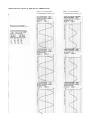
HARMONIC FORMULAE
24
Total Harmonic Distortion
Factor of Voltage
THDF V =
Total Harmonic Distortion
Factor of Current
THDF A =
∑V
2
k
or
24
2
2
k
∑A
2
k
2
V1
Vrms
Arms
where
24
∑V
2
or
24
2
2
k
∑A
A1
Vk, Ak = V, I harmonic of 50/60 Hz fundamental
k = 2, 3,..., 24th harmonic computed by means of a DFT
Cos∅ fnd = Cosinus of the phase angle between V1 and A1
8.7
PRINTER SPECIFICATIONS
• Number of columns:
42.
• Characters:
5x7 matrix
• Print speed:
1 line per second.
• Paper:
55g/m2 pure cellulose smooth.
• Paper width:
57 mm.
• Paper length:
16 m.
• Print functions:
Manual (PRINT key on instrument’s front panel prints out all measurements taken).
Automatic (printouts generated automatically at time intervals of 1 to 99 minutes as programmed on calendarclock). Congruity of printed measurements ensured by reference to start of printout time.
8.8
CLAMP METER SPECIFICATIONS
• Measurement range:
from 0,1 A to 1200 A.
• Frequency range:
from 30 Hz to 10 kHz.
• Ratio:
1000A/1Vrms.
• Accuracy:
200... 1000A ≤ 0,5% ≤ 0,5° phase angle
50... 200A ≤ 0,75% ≤ 0,75° phase angle
10...
50A ≤ 1,5% ≤ 1,5°
phase angle
0,1... 10A ≤ 3% + 0,1 mV
40
• Construction standards:
(LVD) IEC 1010-1, IEC 1010-2-032 600V CAT III, pollution degree 2
(EMC) EN50081-1 class B
EN50082-2
• Overload protection:
Max. 1200 A for 40'
• Output impedance:
1Ω.
8.9
ON BOARD MEMORY SPECIFICATIONS
• Size:
1 Megabyte (7840 records in Standard LOG, 677 records in Sample LOG)
• Type:
Non-volatile serial flash-memory
• Number of writings:
10.000 write-cycles min.
9
OPERATION AND MAINTENANCE OF INSTRUMENT
9.1
CAUTION AND HINTS
Always remember the following points in order to get the best from your instrument:
− The instrument is designed to operate under mains power. It should be used on the power of the internal
rechargeable Ni-Cd battery only for short intervals.
− The battery recharges automatically when the instrument is connected to the mains.
− The I/O switch does not disconnet the instrument from the mains, but merely switches off the instrument's low
voltage circuits.
− The backlight should be switched off when the instrument is running off the battery. The backlight can be turned on
temporarily by means of a button on the rear panel.
− Regularly check for the amount of paper left and for printer cartridge wear. Do not allow the printer to operate
without paper as this causes rapid wear.
− If the printer does not work, an internal fuse may have blown. Refer the instrument to an authorised assistance
centre.
41
ANNEX A
A.1
Characteristics of the MICROVIP3 PLUS
Rs232 serial communication software
protocol
The software communication protocol complies with the ASCII (7 bits) MODBUS protocol.
- Selected transmission mode: ASCII
- Coding system: HEX (uses printable ASCII
characters: 0-9, A-F).
- Error detection mode: LRC
- Serial protocol characteristics:
- Baud rate: 1200, 2400, 4800, 9600, 19200, 38400
- Data bits: 7/8
- Parity bits: None/Odd/Even
- Stop bits: 1/2
The commands implemented by the MODBUS protocol are:
• Reading of all measurements
• Date and time reading
• Disabling/enabling of the keyboard
• Power peaks and averages reset
• Energy meters reset
• Programming of current transformer ratios
• Programming of voltage transformer ratios
• Selection of the three-phase system type:
STAR/DELTA
• Selection of option: STANDARD1,
STANDARD2, COGENERATION4
• Programming of the integration time for average
values
• Data and time programming
List of MODBUS protocol commands implemented and their limitations
READING OF N. WORDS
P.C.
MICROVIP3 PLUS
:,AA,03H,SSSS,WWWW,LRC,CR,LF
- - - - - - ->
<- - - - - - -:,AA,03H ,BB,D1,..,Dn,LRC,CR,LF
where:
- AA
- 03H
- SSSS
- WWWW
- LRC
- CR
- LF
- BB
- D1,..,Dn
= 01 = address of the MICROVIP3 PLUS (2 bytes ASCII)
= Code of the command for reading of N words (2 bytes ascii)
= Address from which the reading starts (4 bytes ascii)
= Number of words to be read (4 bytes ascii): max. 70 words
= Longitudinal Redundancy Check (2 bytes ascii)
= 0DH (1 byte ascii)
= 0AH (1 byte ascii)
= Number of bytes read (2 bytes ascii)
= Bytes of data read (2 * Num.ascii bytes)
COMMANDS IMPLEMENTED:
- Eeprom reading
(0000H <= SSSS <= 00FEH; Valid range: 0000H-00FFH NOTE::
The address must always be even)
- Internal RAM reading
- External RAM reading
(SSSS = 0810H)
(SSSS = 0FE00H)
42
WRITING OF 1 BIT
P.C.
MICROVIP3 PLUS
:,AA,05H,NNNN,bbbb,LRC,CR,LF
- - - - - - ->
<- - - - - - -:,AA,05H,NNNN,bbbb,LRC,CR,LF
where:
- AA
- 05H
- NNNN
= 01 = address of the MICROVIP3 PLUS (2 bytes ASCII)
= Code of the command for writing of 1 bit (2 bytes ascii)
= Number of the bit to be written (4 bytes ascii):
0000H <= Number of the bit <= 0003H or number of the bit = FFFEH
= FF00H: bit = 1; 0000H: bit = 0 (4 bytes ascii).
= Longitudinal Redundancy Check (2 bytes ascii)
= 0DH (1 byte ascii)
= 0AH (1 byte ascii)
- bbbb
- LRC
- CR
- LF
COMMANDS IMPLEMENTED:
- Keyboard disabling
- Keyboard enabling
- Peaks and averages reset
- Meters reset
(NNNN = 0000H; bbbb = FF00H)
(NNNN = 0000H; bbbb = 0000H)
(NNNN = 0001H; bbbb = FF00H)
(NNNN = 0002H; bbbb = FF00H)
WRITING OF 1 WORD
P.C.
MICROVIP3 PLUS
:,AA,06H,SSSS,D1,D2,LRC,CR,LF
- - - - - - ->
<- - - - - - -:,AA,06H,SSSS,D1,D2,LRC,CR,LF
where:
- AA
- 06H
- SSSS
- D1
- D2
- LRC
- CR
- LF
= 01 = address of the MICROVIP3 PLUS (2 bytes ASCII)
= Code of the command for writing of 1 word (2 bytes ascii)
= Address from which writing starts (4 bytes ascii)
= 1st datum to be written (2 bytes ascii)
= 2nd datum to be written (2 bytes ascii)
= Longitudinal Redundancy Check (2 bytes ascii)
= 0DH (1 byte ascii)
= 0AH (1 byte ascii)
COMMANDS IMPLEMENTED:
- Writing in eeprom of the CT coefficient K
(4 consecutive writing commands)
-1) SSSS = 003AH:
- D1 = CT primary (LSB decimal mantissa)
- D2 = CT primary (MSB decimal mantissa )
-2) SSSS = 003CH:
- D1 = CT primary exponent
- D2 = not significant
-3) SSSS = 003EH:
- D1 = CT secondary (LSB decimal mantissa)
- D2 = CT secondary (MSB decimal mantissa)
-4) SSSS = 00040H:
- D1 = CT secondary exponent
- D2 = not significant
Example writing CT :
Set TA = 1000/1
Set primary
:01 06 00 3A E8 03 Check CR LF
:01 06 00 3C 00 00 Check CR LF
Eco
Eco
Set secondary
:01 06 00 3E E8 03 Check CR LF
Eco
43
:01 06 00 40 FD 00 Check CR LF
.
Eco
- CT primary
- CT secondary
- CT K
= 1000 exp 0 = 1000 A
= 1000 exp –3 = 1.000 V
= 1000 / 1 = 1000 A. / 1 V
- Writing in eeprom of the PT coefficient K
(2 consecutive writing commands)
-1) SSSS = 0030H:
- D1 = PT primary in volts (in BCD) (middle 2 digits)
- D2 = PT primary in volts (in BCD) (first 2 digits)
-2) SSSS = 002FH:
- D1 = PT primary in volts (in BCD) (last 2 digits)
- D2 = PT secondary (in binary) (actually written in 0035H)
- 00H = 57,7 volts
- 10H = 63,5 volts
- 20H = 100 volts
- 30H = 110 volts
- 40H = 115 volts
- 50H = 120 volts
- 60H = 173 volts
- 70H = 190 volts
- 80H = 200 volts
- 90H = 220 volts
NOTE: Only the high nibble of datum D2 is written.
NOTE: If for any reason only one of the two writing commands is written (because of a break in the line, etc.) the
malfunction must be recorded (on P.C.) since after each command the PT primary and secondary are immediately
updated. This might lead to a lack of synchronization between the primary/secondary values set and the PT coefficient K
implemented (not updated until after the second command). Also remember that whenever the PT primary is greater than
9999 V the value is rounded up or down for calculation of the K, since the internal precision is of 4 digits (the most
significant).
E.g.
- PT primary
- PT secondary
- PT K
= 100050 V
= 100 V
= 100100 / 100 = 1001 V.
- Writing in eeprom of the flag for selection of Start/Delta system
(SSSS = 0001H; D2 = 09H):
Structure of datum "D1":
7
6
5
4
3
2
1
0
bit
0
0
==> Star
0
1
==> Delta
(any others not used)
NOTE: Only bits 3 and 0 of datum D1 are written at the address indicated; D2 is processed as a template of the bits to be
written but is not written.
- Writing in eeprom of the flag for selection of Standard 1/Standard 2/Cogeneration 4
(2 consecutive writing commands)
-1) SSSS = 0001H; D2 = 02H:
Structure of datum "D1":
7
6
5
4
-
3
-
2
-
1
0
0
-
-
-
-
1
-
-
-
-
bit
==> no cogeneration
(standard 1/2)
==> cog. 4 (Wh, VArh,
-Wh, -VArh).
NOTE: Only bit 1 of datum D1 is written at the address indicated; D2 is processed as a template of the bit to be written
but is not written.
-2) SSSS = 00CDH; D2 = 80H:
Structure of datum "D1":
7
6
5
4
0
1
-
3
-
2
-
1
-
0
-
bit
==> Standard 1 (Wh, VArh)
==> Standard 2 (Wh, VAh).
44
NOTE: Only bit 7 of datum D1 is written at the address indicated; D2 is processed as a template of the bit to be written
but is not written.
NOTE: If for any reason only one of the two writing commands is written (because of a break in the line, etc.) the
malfunction must be recorded (on P.C.) since after each command the selection bit is immediately updated. This might
lead to a selection error since the 2 selection bits are paired as follows:
- D1 (1st command) = 00H and
- D1 (1st command) = 00H and
- D1 (1st command) = 02H and
- D1 (1st command) = 02H and
D1 (2nd command) = 00H <===> Standard 1
D1 (2nd command) = 80H <===> Standard 2
D1 (2nd command) = 00H <===> Cogener. 4
D1 (2nd command) = 80H <===> Cogener. 4
(possible not used)
NOTE: For the COG4 selection only the 1st control is needed (2nd one is powerless).
- Writing in eeprom of the integration time for average value (SSSS = 0001H; D2 = 0C4H):
7
0
0
1
1
0
0
1
1
6
0
1
0
1
0
1
0
1
5
-
4
-
3
-
2
0
0
0
0
1
1
1
1
1
-
0
-
bit
==> 10 minutes
==> 15 minutes
==> 20 minutes
==> 30 minutes
==> 60 minutes
==> 1 minute
==> 2 minutes
==> 5 minutes
NOTE: Only bits 7, 6 and 2 of datum D1 are written at the address indicated; D2 is processed as a template of the bit to
be written but is not written.
- Writing in RAM/eeprom of the date and time (3 consecutive writing commands):
-1) SSSS = 0DFCH:
- D1 = minutes in BCD
- D2 = hours in BCD
-2) SSSS = 0DFEH:
- D1 = day in BCD
- D2 = month in BCD
-3) SSSS = 0C4BH:
- D1 = year in BCD
- D2 = 00H
NOTE: Only datum D1 is written at the address indicated; D2 is ignored.
- Reading in eeprom of the CT coefficient K
P.C.
:,AA,03H,003A,0004, LRC, CR,LF
MICROVIP3 PLUS
------>
<------
:,AA,03H,04,D1,D2,D3,D4,D5,D6,D7,D8,LRC,CR,LF
where:
-AA
-03H
-003A
-0004
-LRC
-CR
-LF
-08
-D1
-D2
-D3
-D4
-D5
-D6
-D7
-D8
= 01 = address of the MICROVIP3 PLUS selected(2 bytes ascii)
= Code of the command for reading of N words(2 bytes ascii)
= address from which the reading starts (8 bytes ascii)
= Number of words to be read (8 bytes ascii)
= Longitudinal Redundancy Check (2 bytes ascii)
= 0DH (1 byte ascii)
= 0AH (1 byte ascii)
= Number of bytes read
= CT primary in amps(LSB decimal mantissa)
= CT primary in amps(MSB decimal mantissa)
= CT primary exponent
= not significant
= CT secondary (LSB decimal mantissa)
= CT secondary (MSB decimal mantissa)
= CT secondary exponent
= not significant
E.g.
- CT primary = 1000A
- CT secondary = 1.0V
- CT K = 1000/1
45
Reading string :
: 01 03 003A 0004 BE CR LF
Response from MICROVIP3 PLUS :
: 01 03 08 E8030000E8 03 FD 00 21 CR LF
- Reading in eeprom of the PT coefficient K
P.C.
MICROVIP3 PLUS
:,AA,03H,002E,0004, LRC, CR,LF
------>
<------ :,AA,03H,08,D1,D2,D3,D4,D5,D6,D7,D8,LRC,CR,LF
where:
-AA
-03H(04H)
-002E
-0004
-LRC
-CR
-LF
-08
-D1
-D2
-D3
-D4
-D5
-D6
-D7
-D8
= 01 = address of the MICROVIP3 PLUS selected(2 bytes ascii)
= Code of the command for reading of N words(2 bytes ascii)
= address from which the reading starts (4 bytes ascii)
= Number of words to be read (4 bytes ascii)
= Longitudinal Redundancy Check (2 bytes ascii)
= 0DH (1 byte ascii)
= 0AH (1 byte ascii)
= Number of bytes read
= not used
= PT primary in volts(in BCD, last 2 digits)
= PT primary in volts(in BCD middle 2 digits)
= PT primary in volts(in BCD first 2 digits)
= not used
= not used
= not used
= PT secondary (in binary)
-0XH = 57,7 Volts
-1XH = 63,5 Volts
-2XH = 100 Volts
-3XH = 110 Volts
-4XH = 115 Volts
-5XH = 120 Volts
-6XH = 173 Volts
-7XH = 190 Volts
-8XH = 200 Volts
-9XH = 220 Volts
Note:
X means don’t care in order to read only the high nibble of datum D8 .
E.g. :
-PT primary
= 200400 Volts
-PT secondary = 100 Volts
-PT K
= 200400/100 = 2004
Reading string :
: 0103 002E 0004 CA cr lf
Response from MICROVIP3 PLUS :
: 01 03 08 FC00042050001023 51 cr lf
- Reading in eeprom of the integration time for average values
P.C.
:,AA,03H,0000,0001, LRC, CR,LF
<------
MICROVIP3 PLUS
------>
:,AA,03H,02,D1,D2,LRC,CR,LF
where:
46
-AA
-03H
-0000
-0001
-LRC
-CR
-LF
-02
-D1
-D2
= 01= address of the MICROVIP3 PLUS selected (2 bytes ascii)
= Code of the command for reading of N words (2 bytes ascii)
= address from which the reading starts (4 bytes ascii)
= Number of words to be read (2 bytes ascii)
= Longitudinal Redundancy Check (2 bytes ascii)
= 0DH (1 byte ascii)
= 0AH (1 byte ascii)
= Number of bytes read
= not used
= b7 b6 b5 b4 b3 b2 b1 b0
bit
0 0 - - - 0 - ==> 10 minutes
0 1 - - - 0 - ==> 15 minutes
1 0 - - - 0 - ==> 20 minutes
1 1 - - - 0 - ==> 30 minutes
0 0 - - - 1 - ==> 60 minutes
0 1 - - - 1 - ==> 1 minutes
1 0 - - - 1 - ==> 2 minutes
1 1 - - - 1 - ==> 5 minutes
E.g. :
-Integration Time = 15’
Reading string :
: 01 03 0000 0001 FB cr lf
Response from MICROVIP3 PLUS :
: 01 03 02 01 40 B9 cr lf
- Reading in eeprom of the flags for selection of the Star/Delta switching
P.C.
:,AA,03H,0000,0001, LRC, CR,LF
<------
MICROVIP3 PLUS
------>
:,AA,03H,02,D1,D2,LRC,CR,LF
where:
-AA
-03H
-0000
-0001
-LRC
-CR
-LF
-02
-D1
-D2
= 01 = address of the MICROVIP3 PLUS selected(2 bytes ascii)
= Code of the command for reading of N words(2 bytes ascii)
= address from which the reading starts (4 bytes ascii)
= Number of words to be read (2 bytes ascii)
= Longitudinal Redundancy Check (2 bytes ascii)
= 0DH (1 byte ascii)
= 0AH (1 byte ascii)
= Number of bytes read
= not used
= b7 b6 b5 b4 b3 b2 b1 b0
bit
- - - - 0 - - 0
==> Star
- - - - 0 - - 1
==> Delta
E.g. :
-Insertion "Delta"
Reading string :
: 01 03 0000 0001 FB cr lf
Response from MICROVIP3 PLUS :
: 01 03 02 01 51 A8 cr lf
47
- Reading in eeprom of the flag for selection of Standard /Cogeneration 4
P.C.
:,AA,03H,0000,0001, LRC, CR,LF
<------
MICROVIP3 PLUS
------>
:,AA,03H,02,D1,D2,LRC,CR,LF
where:
-AA
-03H
-0000
-0001
-LRC
-CR
-LF
-02
-D1
-D2
= 01 = address of the MICROVIP3 PLUS selected(2 bytes ascii)
= Code of the command for reading of N words(2 bytes ascii)
= address from which the reading starts (4 bytes ascii)
= Number of words to be read (2 bytes ascii)
= Longitudinal Redundancy Check (2 bytes ascii)
= 0DH (1 byte ascii)
= 0AH (1 byte ascii)
= Number of bytes read
= not used
= b7 b6 b5 b4 b3 b2 b1 b0
bit
- - - - 0 ==> no cogen eration (S tandard 1 /2)
- - - - 1 ==> cog. 4 (W h, V A rh, -W h , -V A rh).
E.g. :
-Selection Cogeneration 4
Reading string :
: 01 03 0000 0001 FB cr lf
Response from MICROVIP3 PLUS :
: 01 03 02 01 52 A7 cr lf
- Reading in eeprom of the flag for selection of Standard 1/Standard 2
P.C.
MICROVIP3 PLUS
:,AA,03H,00CC,0001, LRC, CR,LF
<------
------>
:,AA,03H,02,D1,D2,LRC,CR,LF
where:
-AA
-03H
-00CC
-0001
-LRC
-CR
-LF
-02
-D1
-D2
= 01 = address of the MICROVIP3 PLUS selected(2 bytes ascii)
= Code of the command for reading of N words(2 bytes ascii)
= address from which the reading starts (4 bytes ascii)
= Number of words to be read (2 bytes ascii)
= Longitudinal Redundancy Check (2 bytes ascii)
= 0DH (1 byte ascii)
= 0AH (1 byte ascii)
= Number of bytes read
= not used
= b7 b6 b5 b4 b3 b2 b1 b0
bit
0 - - ==> Standard 1 (Wh, VArh)
1 - - ==> Standard 2 (Wh, VAh)
Note: this reading has meaning only if no cogeneration is selected
E.g. :
-Standard 2
Reading string :
: 01 03 00CC 0001 2F cr lf
Response from MICROVIP3 PLUS :
: 01 03 02 02 82 76 cr lf
48
LIST OF THE ERROR STRINGS IMPLEMENTED AND THEIR MEANING
ILLEGAL FUNCTION.
Error generated by reception of an unknown function code.
P.C.
MICROVIP3 PLUS
<- - - - - - - :,AA,FF,01H,LRC,CR,LF
where:
- AA
- FF
- LRC
- CR
- LF
= 01 = address of the MICROVIP3 PLUS (2 bytes ASCII)
= Code of the command received with bit 7 forced to 1 (2 bytes ascii);
e.g. 81H: code of the command for reading 1 bit (not recognized)
= Longitudinal Redundancy Check (2 bytes ascii)
= 0DH (1 byte ascii)
= 0AH (1 byte ascii)
ILLEGAL DATA ADDRESS.
Error generated by reception of an address relating to the data which is outside the valid range established for that type of
command.
E.g.
In a reading command of N words, if "SSSS > 0FDE" this type of error is generated.
P.C.
MICROVIP3 PLUS
<- - - - - - - :,AA,FF,02H,LRC,CR,LF
where:
- AA
- FF
- LRC
- CR
- LF
= 01 = address of the MICROVIP3 PLUS s(2 bytes ascii)
= Code of the command received with bit 7 forced to 1 (2 bytes ascii);
e.g. 83H: code of the command for reading N words
= Longitudinal Redundancy Check (2 bytes ascii)
= 0DH (1 byte ascii)
= 0AH (1 byte ascii)
ILLEGAL DATA VALUE.
Error generated by reception of a datum which is outside the valid range established for that type of command.
E.g.
In a reading command of N words, if "WWWW > 0046 (70)" this type of error is generated.
P.C.
MICROVIP3 PLUS
<- - - - - - - :,AA,FF,03H,LRC,CR,LF
where:
- AA
- FF
- LRC
- CR
- LF
= 01 = address of the MICROVIP3 PLUS (2 bytes ascii)
= Code of the command received with bit forced to 1 (2 bytes ascii);
e.g. 83H: code of the command for reading N words
= Longitudinal Redundancy Check (2 bytes ascii)
= 0DH (1 byte ascii)
= 0AH (1 byte ascii)
FAILURE IN ASSOCIATED DEVICE.
Error generated by reception of a non hexadecimal (ascii) character.
The valid Hex characters are: 0-9, A-F.
P.C.
MICROVIP3 PLUS
<- - - - - - - :,AA,FF,04H,LRC,CR,LF
where:
- AA
- FF
- LRC
- CR
- LF
= 01 = address of the MICROVIP3 PLUS (2 bytes ascii)
= Code of the command received with bit 7 forced to 1 (2 bytes ascii);
e.g. 83H: code of the command for reading N words
= Longitudinal Redundancy Check (2 bytes ascii)
= 0DH (1 byte ascii)
= 0AH (1 byte ascii)
NO RESPONSE.
Communications error generated by:
- Overrun or framing error
49
- Initial character error (":")
- Address selected not valid
- LRC error
- CR error
- LF error
- Any type of error detected on a "radio broadcasting" command (address = 00H).
HOW THE LRC IS CALCULATED
The LRC is calculated as follows.
- all the bytes to be transmitted before the LCR are added together, except for the string start
character (:).
- the value calculated is then divided by 256 and the remainder is noted
- the remainder is then subtracted from 256 to obtain the desired LRC.
Example:
01H,03H,FE00H,0021H,LRC,CR,LF
The LRC will be calculated as follows:
- 01H + 03H + FEH + 00H + 00H + 21H = 123H (291)
- 123H / 100H (256) = 01H RESTO = 23H (35)
- 100H (256)- 23H = DDH
therefore:
- LRC = DDH.
50
Description of the operational reading functions implemented
READING OF ALL MEASUREMENTS
This is carried out by reading 65 words starting from the address 0810H or 0FE00H.
The meaning of the 130 bytes received is as follows:
- Type of instrument (TIPVIP = 0DH = 13 (Vip Energy))
- Instrument options (OPTION) (1st byte):
bit 7 = 0 (not used)
7
-
6
0
5
1
4
1
3
-
2
-
1
-
0
1
bit
==> Microvip3 Plus
1
-
0
-
bit
==> 10 minutes
==> 15 minutes
==> 20 minutes
==> 30 minutes
==> 60 minutes
==> 1 minute
==> 2 minutes
==> 5 minutes
bit 3 = 0 (not used)
bit 2 = 0 (not used)
bit 1 = 0 (not used)
bit 0 = 1 = serial option present
- Instrument options (OPTIO2) (2nd byte):
bit 7, 6, 5, 4, 3, 2, 1, 0 = 0 (not used)
- Instrument setup (CONFIG) (1st byte):
bit 7, 6, 2 = Integration time for averages:
7
6
5
4
3
2
0
0
0
0
1
0
1
0
0
1
1
0
0
0
1
0
1
1
1
0
1
1
1
1
bit 5, 4, 3 = 0 (not used)
7
-
Bit 1 = Selection of cogeneration / no cogeneration:
6
5
4
3
2
1
0
0
1
-
bit
==> no Cog. 4 (Standard1 / 2)
==> Cogeneration 4 active
7
-
Bit 0 = Selection of switching type:
6
5
4
3
2
-
1
-
0
0
1
bit
==> Star
==> Delta
bit
==> Standard 1 (Wh, varh) active
(with bit 1 of CONFIG = 0)
==> Standard 2 (Wh,VAh) active
(with bit 1 of CONFIG = 0)
- Instrument setup (CONFI2) (2nd byte):
bit 7 = selection of Standard 1/2:
7
6
5
4
3
0
-
2
-
1
-
0
-
1
-
-
-
-
-
-
-
Note :
7
-
bit 0 = keyboard Enabling/Disabling
6
5
4
3
-
2
-
1
-
- Three-phase voltage (V)
- Three-phase current (I)
- Three-phase active power (W)
- Three-phase cosphi
- Phase L1 voltage (V)
- Phase L2 voltage (V)
- Phase L3 voltage (V)
- Phase L1 current (I)
- Phase L2 current (I)
- Phase L3 current (I)
- Phase L1 active power (W)
- Phase L2 active power (W)
51
0
0
1
bit
==> keyboard enabled
==> keyboard disabled
- Phase L3 active power (W)
- Phase L1 cosø
- Phase L2 cosø
- Phase L3 cosø
- Phase L1 reactive power (VAr)
- Phase L2 reactive power (VAr)
- Phase L3 reactive power (VAr)
- Phase L1 apparent power (VA)
- Phase L2 apparent power (VA)
- Phase L3 apparent power (VA)
- 6 ASCII characters = 30 Hex
- 6 ASCII characters = 30 Hex
- 6 ASCII characters = 30 Hex
- Three-phase apparent power (VA)
- Three-phase reactive power (VAr)
- Frequency (Hz)
- Positive three-phase kWatthours (single-phase if single-phase is set) (kWh)
- Positive three-phase kVArhours (single-phase if single-phase is set) (kVArh)
- Three-phase average reactive power (single-phase if single-phase is set) (VAr)
- Three-phase average apparent power (single-phase if single-phase is set) (VA)
- Three-phase average active power (single-phase if single-phase is set) (W)
- Three-phase apparent power peaks (single-phase if single-phase is set) (VA)
- Three-phase active power peaks (single-phase if single-phase is set) (W)
- Negative three-phase kWatthours (single-phase if single-phase is set) (kWh) (if Delta system
is selected, or Star system or single-phase switching with the Cogeneration 4 option
- Negative three-phase kVArhours (single-phase if single-phase is set) (kVArh) (if Delta system
is selected, or Star system or single-phase switching with the Cogeneration 4 option
5 ASCII charcters = 30 Hex
1 ASCII character = 30 Hex
- WITH SINGLE-PHASE OPTION SELECTED:
the string is always 65 words long. The three-phase measurement and that of phase L1 coincide.
The measurements of phases L2 and L3 are not calculated.
DATA AND HOUR READING
This is carried out by reading 3 words starting from address 0DFCH.
The meaning of the 6 bytes received is as follows:
- Minutes
- Hours
- Day
- Month
- Year
- Datum to be rejected (1 byte)
NOTE: All the data received are in BCD.
52
A.2 Q-Basic example for MICROVIP3 PLUS reading
'
'
'
'
'
EXAMPLE OF MICROVIP3 PLUS READING
INSTRUMENT TYPE
: MICROVIP3 PLUS
PHISICAL ADDRESS
: 01
TRANSMISSION PARAMETERS : 9600 baud, NO par, 1 Stop BIT
DECLARE SUB Pause (n!)
DECLARE SUB SetArrayMeasures ()
DECLARE FUNCTION CheckLrc! (EnergyReply$)
DECLARE SUB ShowData (EnergyReply$)
DECLARE FUNCTION AsciiToFloat! (Data$)
DECLARE FUNCTION AsciiHexToDec! (A$)
DECLARE FUNCTION LRC$ (strng$)
CONST TRUE = -1: CONST FALSE = 0
TYPE Measure
Nome AS STRING * 6
NCh AS INTEGER
OutRow AS INTEGER
OutCol AS INTEGER
END TYPE
DIM SHARED Measures(40) AS Measure '
CR$ = CHR$(13)
LF$ = CHR$(10)
'Name,OutRow,OutCol
DATA V,1,1,A,1,2,W,1,3,PF,2,1,V1,3,1,V2,3,2,V3,3,3,I1,4,1,I2,4,2,I3,4,3
DATA W1,5,1,W2,5,2,W3,5,3,PF1,6,1,PF2,6,2,PF3,6,3
DATA VAr1,7,1,VAr2,7,2,VAr3,7,3
DATA VA1,8,1,VA2,8,2,VA3,8,3,CF1,9,1,CF2,9,2,CF3,9,3
DATA VA,10,1,VAr,10,2,Hz,10,3
DATA kWh,11,1,kVArh,11,2,AvgVAr,12,1,AvgVA,12,2,AvgW,12,3
DATA PeakVA,13,1, PeakW,13,2,kWh1,14,1,kWh2,14,2,kWh3,14,3
SetArrayMeasures
DO
OPEN "COM1: 9600,N,7,1" FOR RANDOM AS #1
' Standard request of 65 words (41H) starting from addr. FE00
' Instrument's address=01 , Reading Command=03
Request$ = "0103FE000041"
Request$ = ":" + Request$ + LRC(Request$) + CR$ + LF$
PRINT #1, Request$
INPUT #1, EnergyReply$
Pause (5) 'pause between two requests
' Read clock
Request$ = "01030DFC0003"
Request$ = ":" + Request$ + LRC(Request$) + CR$ + LF$
PRINT #1, Request$
INPUT #1, Tim$
CLOSE #1
CLS : LOCATE 1, 1
PRINT EnergyReply$
IF CheckLrc(EnergyReply$) THEN
ShowData (EnergyReply$)
END IF
Min$ = MID$(Tim$, 8, 2): HH$ = MID$(Tim$, 10, 2)
DD$ = MID$(Tim$, 12, 2): MM$ = MID$(Tim$, 14, 2)
YY$ = MID$(Tim$, 16, 2)
LOCATE 23, 1: PRINT "Energy Time = "; HH$; ":"; Min$;
PRINT " - "; DD$; "/"; MM$; "/"; YY$
Pause (5)
LOOP WHILE INKEY$ = ""
END
FUNCTION AsciiHexToDec (A$)
'Converts a hexadecimal numbers, written as two ascii char., into a decimal
MSC$ = LEFT$(A$, 1) ' first char
LSC$ = RIGHT$(A$, 1) ' second char
IF MSC$ >= "A" THEN
TEMP = (ASC(MSC$) - ASC("A") + 10) * 16
ELSE
TEMP = VAL(MSC$) * 16
END IF
IF LSC$ >= "A" THEN
TEMP = TEMP + (ASC(LSC$) - ASC("A") + 10)
ELSE
TEMP = TEMP + VAL(LSC$)
END IF
AsciiHexToDec = TEMP
END FUNCTION
FUNCTION AsciiToFloat (Data$)
'Convert a number from the Energy reply's format to a float
Exponent = AsciiHexToDec(RIGHT$(Data$, 2))
IF Exponent > 200 THEN Exponent = Exponent - 256 ' FF=-1, FE=-2 ect...
53
Num$ = ""
FOR k = 1 TO LEN(Data$) - 3 STEP 2
'Rewrites the whole number from the most significant couple of digits
' to the last significant
Num$ = MID$(Data$, k, 2) + Num$
NEXT k
IF LEFT$(Num$, 1) = "8" THEN
'Negative number
Num$ = "-" + RIGHT$(Num$, LEN(Num$) - 1)' Cut char. "8" and add "-"
END IF
AsciiToFloat = VAL(Num$) * 10 ^ Exponent
END FUNCTION
FUNCTION CheckLrc (EnergyReply$)
'Compares the Received and the Calculated LRC
EnergyReply$ = MID$(EnergyReply$, 2, LEN(EnergyReply$)) ' Cut char. ":"
RxLrc$ = RIGHT$(EnergyReply$, 2)
EnergyReply$ = LEFT$(EnergyReply$, LEN(EnergyReply$) - 2)' Cut LRC
CalcLrc$ = LRC(EnergyReply$)
LOCATE 4, 35
IF RxLrc$ <> CalcLrc$ THEN
PRINT "Communication Error !"
CheckLrc = FALSE
ELSE
PRINT "Communication OK ! "
CheckLrc = TRUE
END IF
END FUNCTION
FUNCTION LRC$ (strng$)
'Longitudinal Redundancy Check calculation
TEMP = 0
FOR i = 1 TO LEN(strng$) STEP 2
A$ = MID$(strng$, i, 2)
DECVALUE = AsciiHexToDec(A$)
TEMP = TEMP + DECVALUE ' sum of all character
NEXT i
TEMP = TEMP MOD 256
TEMP = 256 - TEMP
LRC$ = HEX$(TEMP)
END FUNCTION
SUB Pause (n)
FOR i = 1 TO n: PLAY "P64": NEXT i
END SUB
SUB SetArrayMeasures
'Reads the label and the required screen position
SHARED Measures AS Measure
FOR i = 1 TO 38:
READ Measures(i).Nome, Measures(i).OutRow, Measures(i).OutCol
Measures(i).NCh = 6
NEXT i
'Counters Lenght = 10 characters
Measures(29).NCh = 10: Measures(30).NCh = 10 'kWh kVArh
Measures(36).NCh = 10: Measures(37).NCh = 10 'kWh1 kWh2
Measures(38).NCh = 10
'kWh3
END SUB
SUB ShowData (EnergyReply$)
' Shows the measures on the screen
SHARED Measures AS Measure
Stepp = 26: PRINT STRING$(80, "Õ")
Pointer = 17
FOR i = 1 TO 38
LOCATE 7 + Measures(i).OutRow, (Measures(i).OutCol - 1) * Stepp + 1
PRINT RTRIM$(Measures(i).Nome); " = ";
Meas$ = MID$(EnergyReply$, Pointer, Measures(i).NCh)
PRINT AsciiToFloat(Meas$)
Pointer = Pointer + Measures(i).NCh
NEXT i
END SUB
54
EXAMPLE OF MODBUS PROTOCOL
REQUEST to the instrument with address 01:
":010308100041A3"+CR+LF
oppure
":0103FE0041BD"+CR+LF
Start Transmission
:
Instrument Address
01
Command
03
memory Address
0810 oppure FE00
#words to read
0041
LRC
A3 oppure BD
End Transmission
0D0A
RESPONSE from instrum. 01 to all measurements request
":0103820D310040001204004301FE0101019980FE3802003802003802004301FE4301FE4301FE3703003703003703009980FE9980F
E
9980FE8084FF2484FF4784FF4103004003004003000000000000000000000201013581000005FF41010000FE61020000FE510200570
2002504FF10030154010100000000000000000000000000000000BF"+CR+LF
Start Transmission
:
Address Command Echo
01
03
# of bytes
82
Type of instrument
Option1 Option2 Config1
0D (MICROVIP3 PLUS)
00
31
40
Config2
00
Volt(412) I (1.43)
120400 4301FE
W (1010) PF(-.99)
V1(238)
010101
9980FE
380200
I1(1.43)
4301FE
I2(1.43)
4301FE
W1(337)
370300
PF3(-.99)
9980FE
000000
Var1(-48)
8084FF
000000
I3(1.43)
4301FE
Var2(-42.4)
2484FF
VA(1020)
020101
000000
AvgVAr(251)
510200
AvgVA(257)
570200
kWh- (.46)
46000000FE
kvarh- (.47)
47000000FE
Data to be discarded
00
W2(337)
370300
VAr3(-44.7)
4784FF
V2(238)
V3(238)
380200
380200
W3(337)
370300
PF1(-.99) PF2(-.99)
9980FE
9980FE
VA1(341)
VA2(340) VA3(340)
410300
400300
400300
Var(-135) Hz(50)
kWh+(1.41)
kVArh+(2.61)
358100 0005FF
41010000FE 61020000FE
AvgW(4.5)
2504FF
PeakVA(3100)
100301
PeakW(1540)
540101
0000000000
LRC
BF
End Transmission
CR+LF (0Dh+0Ah)
55
A.3 Reading of Voltage and Current waveforms samples
-
-
The PC Requests for 200 samples of V and I waveforms are:
Phase 1:
Phase 2:
Phase 3:
0103040000202 Check CR LF
:010305000202 Check CR LF
:010306000202 Check CR LF
Microvip3 Plus Response:
:01 03 D1 D2 D3 D4 D5 D6 D7 D8 D9 V1..V200 D10 D11D12 D13D14 D15 D16 D17 I1..I200 CS CRLF
Where:
: = start of Modbus string
01 = Microvip3 Plus default address
03 = command for data reading
D1 = number of frames inside the data buffer; "frame" means 200 voltage samples (first frame) or 200 current samples (second frame)
D2 = type of the first frame of 200 samples (the lowest nibble is the scale)
E.g.:
Voltage samples, scale 1: D2 = A1 hex
Voltage samples, scale 2: D2 = A2 hex
Voltage samples, scale 3: D2 = A3 hex
D3 = first frame samples number (LSB)
D4 = first frame samples number (MSB)
D5 = first frame samples zero (LSB)
D6 = first frame samples zero (MSB)
D7 = first frame calibration factor (LSB)
D8 = first frame calibration factor (MSB)
D9 = first frame calibration factor (EXP)
V1...V200 = samples of the first frame (voltage buffer)
D10 = type of the second frame of 200 samples ( the lowest nibble is the scale )
E.g.:
Current samples, scale 3: D10 = C3 hex
Current samples, scale 4: D10 = C4 hex
Current samples, scale 6: D10 = C6 hex
D11 = second frame samples number (LSB)
D12 = second frame samples number (MSB)
D13 = second frame samples zero (LSB)
D14 = second frame samples zero (MSB)
D15 = second frame calibration factor (LSB)
D16 = second frame calibration factor (MSB)
D17 = second frame calibration factor (EXP)
I1...I200 = samples of the second frame (current buffer)
CS = checksum Modbus
-
The "snapshot" of 200 voltage and 200 current samples, followed by the values of the frequency of phase 1 and positive/negative kWh and
kvarh can be requested to the instrument as follows:
Phase 1:
Phase 2:
Phase 3:
:010304000021A Check CR LF
:01030500021A Check CR LF
:01030600021A Check CR LF
Microvip3 Plus Response
:01 03 D1 D2 D3 D4 D5 D6 D7 D8 D9 V1..V200 D10 D11 D12 D13 D14 D15 D16 D17 I1..I200
DF0,DF1,DF2,DF3,CWP0,CWP1,CWP2,CWP3,CWP4,CVARP0,CVARP1,CVARP2,CVARP3,CVARP4,
CWN0,CWN1,CWN2,CWN3,CWN4, CVARN0,CVARN1,CVARN2,CVARN3,CVARN4, CS CRLF
Up to I200 the string is the same than the previous one.
The remaining data are:
DF0 = third data frame starting identifier (E0 hexadecimal)
DF1,DF2 = Frequency Hz (BCD) (LSB, MSB)
DF3 = Frequency (hexadecimal) (EXP)
56
CWP0,CWP1,CWP2,CWP3,CWP4 = three-phase positive kWh (BCD)
where CWP4 is the exponent (hexadecimal)
CVARP0,CVARP1,CVARP2,CVARP3,CVARP4 = three-phase positive kvarh (BCD)
where CVARP4 is the exponent (hexadecimal)
CWN0,CWN1,CWN2,CWN3,CWN4 = three-phase negative kWh (BCD)
where CWN4 is the exponent (hexadecimal)
CVARN0,CVARN1,CVARN2,CVARN3,CVARN4 = three-phase negative kvarh (BCD)
where CVARN4 is the exponent (hexadecimal)
Example:
:01 03 D1 D2 D3 D4 D5 D6 D7 D8 D9 V1..V200 D10 D11 D12 D13 D14 D15 D16 D17 I1..I200
E0 (third frame starting )
0005FF (Frequency 50.0 Hz)
41010000FE (kWh 1.41)
61020000FE (kvarh 2.61)
32080080FE (-kWh 8.32)
79040080FE (-kvarh 4.79)
57
A.4
On-board Memory downloading via serial line
Use the following command sequence:
1. 8 bit UART Setting
In order to have a correct download of data stored, UART has to be set to 8 bits.
N.B.
This setup is necessary because the data stored inside the internal memory are in decimal format.
PC Request:
:01 05 0006 0000 LRC crlf
2.
Microvip3Plus Response:
Eco
Request for the Number of stored records:
PC Request:
:01 03 4000 0001 3B crlf
Microvip3Plus Response:
:01 03 02 nnnn LRC crlf
where nnnn = number of stored records
3.
Request for n stored records:
PC Request:
:01 03 xxxx yyyy LRC crlf
Microvip3Plus Response:
:0103 nn rrr...rrr rrr...rrr LRC CR LF
xxxx = Address of the starting record (8000h..9EA0h)
where nn = number of WORDS transmitted ( in the standard Modbus nn
should be the number of bytes !)
yyyy = Number of records to be transmitted
(0001, 0002, 0003 o 0004)
rrr...rrr = it is the record of 113 bytes stored and transmitted in binary
format ( therefore it is necessary an 8 bit transmission ).
Example 1:
PC Request:
:0103 8000 0001 7A CR LF
(request for 1 record of 113 bytes starting from the first address 8000h)
Microvip3 Plus Response (hexadecimal) in case of a campaign of rms meas. in Three-phase, Standard1 mode, Star insertion:
:010339
where
01 = address
03 = reading command
39 = number of transmitted words
D1= 20 (Configuration)
The first byte of each record is that one included in the configuration of the instrument at the moment of the measurement storing inside
the internal memory . Its format is as follows:
Bit 7, 6
Bit 5
Bit 4, 3
Bit 2
Bit 1, 0
= type of campaign
= single-phase/three-phase
= instrument configuration
= type of insertion
= phase number
( 00 = rms meas. 01 = samples )
( 0 = single-phase, 1= three-phase )
( 00 = Standard 1, 01 = Standard 2, 10 = Cog 4 )
( 0 = Star,
1 = Delta )
( 00 = phase 1,
01 = phase 2,
10 = phase 3 )
D2 = 01 (day) D3 = 06 (month) D4 = 63 (year hex )
D5 = 00 (seconds) D6 = 08 (minutes) D7 = 09 (hours)
D8 D9 D10
8C 0F FF ( V = 398 three-phase voltage,
log date: 1 June 1999
log hour: 09:08:00
expressed
as
LSB,
MSB,
EXP )
D11 D12 D13
94 11 FF ( I = 450 A three-phase current,
"
"
"
"
")
D14 D15 D16
40 1F FC ( PF= 0.80,
"
"
"
"
")
D17 D18 D19
C8 05 FF ( W= 148 kW,
"
"
"
"
" )
D20 D21 D22
1C 0C 02 (VA = 310 kVA,
"
"
"
"
")
D23 D24 D25
A0 0A 02 ( var = 272 kvar,
"
"
"
"
")
D26 D27 D28
88 13 FE ( Hz = 50.0,
"
"
"
"
")
58
D29 D30 D31 D32 D33 D34
21 03 45 67 89 56 ( positive Wh equal to 210345.678956 MWh )
where
byte 21 = 2 Wh * 10 exp 11 + 1 Wh * 10 exp 10
byte 03 = 0 Wh * 10 exp 9 + 3 Wh * 10 exp 8
byte 45 = 4 Wh * 10 exp 7 + 5 Wh * 10 exp 6
byte 67 = 6 Wh * 10 exp 5 + 7 Wh * 10 exp 4
byte 89 = 8 Wh * 10 exp 3 + 9 Wh * 10 exp 2
byte 56 = 5 Wh * 10 exp 1 + 6 Wh * 10 exp 0
D35 D36 D37 D38 D39 D40
12 34 56 00 00 00 ( Positive varh equal to 123456.000000 Mvarh )
D41 D42 D43 D44 D45 D46
00 00 12 34 00 00 ( Negative Wh equal to 000012.340000 MWh )
D47 D48 D49 D50 D51 D52
00 34 56 00 00 00 ( Negative varh equal to 003456.000000 Mvarh )
D53 D54 D55
B8 0B 02 ( Average Reactive power peaks = 300 kvar , expressed
as
D56 D57 D58
AC 0D 02 ( Average Apparent power peaks = 350 kVA,
"
"
"
"
")
D59 D60 D61
8C 0A 02 ( Average Active power peaks = 270 kW,
"
"
"
"
")
D62 D63 D64
FC 08 FF (V phase 1 = 230 V,
expressed
as
LSB,
MSB,
EXP )
D65 D66 D67
FC 08 FF (V phase 2 = 230 V,
"
"
"
"
")
D68 D69 D70
FC 08 FF (V phase 3 = 230 V,
"
"
"
"
")
D71 D72 D73
94 11 FF ( I phase 1 = 450 A,
"
"
"
"
")
D74 D75 D76
94 11 FF ( I phase 2 = 450 A,
"
"
"
"
")
D77 D78 D79
94 11 FF ( I phase 3 = 450 A,
"
"
"
"
")
D80 D81 D82
58 20 01 ( W phase 1 = 82.8 kW,
"
"
"
"
")
D83 D84 D85
58 20 01 ( W phase 2 = 82.8 kW,
"
"
"
"
")
D86 D87 D88
58 20 01 ( W phase 3 = 82.8 kW,
"
"
"
"
")
D89 D90 D91
40 1F FC ( PF phase 1 = 0.80,
"
"
"
"
")
D92 D93 D94
40 1F FC ( PF phase 2 = 0.80,
"
"
"
"
")
D95 D96 D97
40 1F FC ( PF phase 3 = 0.80,
"
"
"
"
")
LSB,
MSB,
EXP )
D98 D99 D100 D101 D102 D103 D104 D105 D106 D107 D108 D109 D110 D111 D112 D113
0
0
0
0
0
0
0
0
0
0
0
0
0
0
0
0
D114 = Checksum calculated starting from D1 up to D113 in the following way:
All the bytes from D1 to D113 are summed;
The calculated value is divided by 256 and the remainder is saved;
The remainder is subtracted from 256 to obtain the value stored in D114.
LRC (checksum calculated on the whole string starting from the address up to D114 in the same mode as D114 is calculated )
CR
LF
#*************************************************************************************#
59
Example 2:
PC Request:
:010380000004 77 CR LF
(request for 4 records of 113 bytes each, starting from the first address 8000h)
Microvip3 Plus Response (hexadecimal value) in case of a campaign of samples in Three-phase, Standard 1 mode (i.e. kWh e kvarh energy meters ),
Star insertion.
:0103E2
01 = address
03 = reading command
E2 = number of transmitted words
D1= 40 (configuration)
The first byte of each record is that one included in the configuration of the instrument at the moment of the measurement storing inside
the internal memory . Its format is:
Bit 7, 6 = campaign type
Bit 5 = single-phase / three-phase
Bit 4, 3 = instrument configuration
Bit 2 = insertion type
Bit 1, 0 = phase number
( 00 = rms measure,
( 0 = single-phase,
( 00 = Standard 1,
( 0 = Star,
( 00 = phase 1,
10 = Cog 4)
10 = phase 3)
D2 = 02 (day)
D5 = 00 (seconds)
D3 = 06 (month)
D6 = 03 (minutes)
D8 =
voltage frame starting identifier (the lowest nibble is the scale)
( A1 hex = voltage scale 1, A2 hex = voltage scale 2, A3 hex = voltage scale 3)
first frame number of samples ( C8, 00) (LSB, MSB)
voltage zero (E8, 08) (LSB, MSB)
voltage calibration factor (LSB, MSB, EXP)
200 voltage samples: the phase is indicated by bit 0 and bit 1 of D1
D9, D10 =
D11, D12 =
D13, D14, D15 =
D16..D215 =
D4 = 63 (hex year)
D7 = 09 (hours)
01 = samples)
1 = three-phase)
01 = Standard 2,
1 = Delta)
01 = phase 2,
log date: 2 June 1999
log hour : 09:03:00
D216 =
current frame starting identifier (the lowest nibble is the scale)
(C1 hex = current scale 1, C2 hex = current scale 2, C3 hex = current scale 3)
D217, D218 =
second frame number of samples (C8, 00) (LSB, MSB)
D219, D220 =
current zero (E2, 08) (LSB, MSB)
D221, D222, D223 = voltage calibration factor (LSB, MSB, EXP)
D224..D423 =
200 current samples: the phase is indicated by bit 0 and bit 1 of D1
D424 =
measurement tag identifier (E0)
D425, D426, D427 = Frequency ( 8813 FC = 50.0 Hz) (LSB, MSB, EXP)
D428, D429, D430, D431, D432, D433
21
03
45
67
89 56 (Positive Wh counter equal to 210345.678956 MWh )
where
byte 21 = 2 Wh * 10 exp 11 + 1 Wh * 10 exp 10
byte 03 = 0 Wh * 10 exp 9 + 3 Wh * 10 exp 8
byte 45 = 4 Wh * 10 exp 7 + 5 Wh * 10 exp 6
byte 67 = 6 Wh * 10 exp 5 + 7 Wh * 10 exp 4
byte 89 = 8 Wh * 10 exp 3 + 9 Wh * 10 exp 2
byte 56 = 5 Wh * 10 exp 1 + 6 Wh * 10 exp 0
D434 D435 D436 D437 D438 D439
12 34 56 00 00 00 (Positive varh equal to 123456.000000 Mvarh )
D440 D441 D442 D443 D444 D445
00 00 12 34 00 00 (Negative Wh equal to 000012.340000 MWh )
D446 D447 D448 D449 D450 D451
00 34 56 00 00 00 (Negative varh equal to 003456.000000 Mvarh )
D452 = Checksum calculated from D1 up to D451in the following way:
all the bytes from D1 to D451 are summed;
the calculated value is divided into 256 and the remainder is saved;
the remainder is subtracted from 256 to obtain the value stored in D452.
LRC (checksum calculated on the whole string starting from the address up to D452 in the same mode as D452 is calculated)
CR
LF
4. UART Reset
The UART is reset to the programming value previously set on Microvip3 Plus.
PC Request:
:01 05 0007 0000 LRC crlf
Microvip3Plus Response:
Eco
60