1
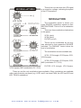
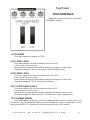
Leipzig
-r / -k
analogue solutions Leipzig
e&oe (c)
1-11-08
1
analogue solutions Leipzig
e&oe (c)
1-11-08
2
SPECIFICATION
Brief Overview:
Leipzig is a self contained TRUE analogue synthesiser. The voice circuitry is entirely
analogue, using all discrete and op-amp components. There is no voice DSP.
Leipzig has a similar sound and specification to the classic Moog Prodigy / Rogue
synthesisers, but with many improvements such as MIDI and more modulation paths.
VCO1
Tune, Glide, PW , PWM, Mod Source & Amount controls, Saw out, Pulse out
VCO2
Tune, Glide , Sync, PWM, Mod Source & Amount controls, Saw out, Pulse out
VCF
Low pass filter: Cut-off, Emphasis, Key Track, ENV1 Mod, Mod Source & Amount
controls
Mixer
Audio source mixer, including external audio inputs
VCA
Mode switch, Output volume
ENV1
ASR envelope with trigger LED
ENV2
ASR envelope with trigger LED
LFO
Square & Triangle waves
Noise Generator
White noise
SUB oscillators
-1 from VCO1
-2 from VCO2
MIDI to CV Converter
16 bit high resolution with auxiliary controller CV2 output (modulation CV)
Many modulation possibilities.
Rotary controls:
25
Rotary switches:
6
analogue solutions Leipzig
e&oe (c)
1-11-08
3
Push button:
1
LEDs:
6
Jack sockets (6.35mm, mono);
3
MIDI Sockets;
2
Rugged steel contruction
Dimensions:
Height: x 5U
Weight:
xKg
Power:
x
Accessories:
Manual
Mains adaptor (230v)
Leipzig-k has the addition of;
Headphone output socket.
CV1, CV2, Gate input and output sockets.
2nd LFO (and VCA) used for modulation, via 4 rotary controls.
Additional rear panel MIDI LED.
LFO2 LED.
Mod wheel.
Pitch Bend Wheel.
LCD, backlit display.
8 eidting buttons.
37 velocity sensative keys.
MIDI Out
analogue solutions Leipzig
e&oe (c)
1-11-08
4
INTRODUCTION
Congratulations on buying the Leipzig synthesiser. Leipzig is part of the Analogue
Solutions range of analogue music equipment. Leipzig is a precision electronic musical
instrument. It combines all the often needed music electronic circuitry to make a music
synthesiser in one compact module.
No compromise has been made with the construction of Leipzig. Cheaper options in
parts have not been used;
Full rugged steel case - no plastic mouldings
Good quality smooth potentiometers, fully sealed against dust
Good quality knobs with spun aluminium caps
High grade double sided lead free circuit board
All power and signal input/outputs have EM filters to remove external noise and improve immunity
High Quality DAC for MIDI to CV conversion - 16bit!
Very stable MIDI to CV conversion
Very stable analogue oscillators
Expensive blue LEDs
Hand built by humans
Lasting quality and appeal with a life far longer than any software plug-in or DSP
synth
APPLICATIONS
MONOSYNTHESISER
Leipzig is for use any time you need analogue sound effects, fat basses, screaming
leads, beeps, tones, zaps, and all the other crazy sounds associated with analogue synthesis. Use in place of your boring digital synths and DSP soft synths.
EFFECTS PROCESSOR
Leipzig has an audio input socket, so you can feed external sounds into the onboard
analogue filters for analogue processing.
analogue solutions Leipzig
e&oe (c)
1-11-08
5
SAFETY INSTRUCTIONS
Please read carefully before using:
• Only use the correct power adaptor - 230V (or 115V whatever your country
needs)
• Never handle the adaptor with wet hands
• Never excessivly bend the adaptor cable or get it trapped or place heavy objects
on it. If the adaptor cable becomes damaged, replace the adaptor.
• Ensure the unit is disconnected from the mains before moving or cleaning.
• Always disconnect the unit from the mains if there is lightning in your area.
• Ensure the unit is on a stable surface, and never place heavy objects on top of it.
• Never allow young children or animals to operate the unit or adaptor.
• Do not use excessive force when using the controls or inserting cables to the connectors.
• The unit should not be operated in the rain or near water and should not be exposed
to moisture. If the unit is brought from a cold environment to a warm one, the unit should
be left to reach the ambient temperature.
• Keep unit away from heat sources, such as radiators, ovens, heaters etc.
• Never allow the unit to get wet. Do not operate it near water, like pools, sinks, bathrooms etc. Do not place beverages on or near it.
• Never open the case or attempt to make repairs. Refer any servicing to a qualified
service personnel.
Preventing damage to other connected devices;
Leipzig has a very high dynamic range. It is capable of produce loud signals of very
high and sub-sonic frequencies that could blow inadequate speakers if played too loud. It
is recommended that input levels to external equipement (mixers, amp's etc.) is kept low
when first connected, and then sowly increased to a userable level.
Maintenance Instructions
Any cleaning of the the case should be done with a clean lint-free cloth. DO NOT
USE SOLVENTS OR CLEANERS, as this will deteriorate the exterior appearance of the
equipment.
Mounting
Mounting does not mean 'place on the wall' or 'to make love to' in this instance. Place
the unit soundly on any stable surface so he cannot fall off or over, causing it or yourself
injury.
analogue solutions Leipzig
e&oe (c)
1-11-08
6
CIRCUITS IN DETAILS
Here follows details on all the sockets and controls, with brief simplified explanations
of what the circuits do. We have not gone into technical details on how and exactly what
each circuit does but tried to explain each control's function and effect.
Anyone who has used synthesisers before should be familiar with the terms used and
therefore be able to predict their behaviour and how they affect the sound. The best way
to learn how to use Leipzig is to go straight ahead and play with it. Reading of this manual
may only be neccessary for finer operational detail.
VCO 1 & 2
The voltage controlled oscillators
(VCOs 1 and 2) produce the raw audio
waveform usually used as the initial source
for sound creation. They provide cyclic audio
waveforms that can be pitched. VCOs usually receive treatment from the VCF to turn
their basic tones into pleasant sounds.
TUNE
Left TUNE is a master tune affecting BOTH
oscillators.
Right TUNE is a detune affecting only oscillator 2.
The detune TUNE control can be used for
playing VCO2 at intervals, like, say, a 3rd
up from VCO1.
GLIDE
Two independent GLIDE controls (portamento) for the oscillators. Each time you
play a new note, the pitch will glide from
the last note to the new note. The GLIDE
control alters the speed. At minimum there
is no glide.
Pulse Width
(Just below VCO1 GLIDE control). For
VCO1 only. This alters the pulse width for
VCO1's square wave (alters the 'duty cycle').
If you do not understand this, don't worry
about it! Just turn it and hear how the tone changes.
analogue solutions Leipzig
e&oe (c)
1-11-08
7
SYNC
VCO2 only. This switch routes a sync signal to VCO2. Oscillator sync is where a
master signal (selected by the switch) will reset the waveform of a slave signal (VCO2 in
this case) each time the master waveform starts a new cycle.
Try the different settings and listen to the effect. You may have to modulate the pitch
of either VCO1 or VCO2 to enhance the effect. There is a balancing act between the pitch
of the two sound sources (usually the 2 VCOs) to get a good effect.
Sync source choices are;
VCO1 square wave
LFO square wave
EXTernal signal
Off (flat line symbol)
PWM
Two independent pulse width modulation controls (PWM), one for each VCO. This
allows modulation of the square wave 'duty cycle'. Once again, don't worry about this
technically, just enjoy the effect!.
Turn to the left for LFO triangle wave modulation.
Turn to the right for Envelope 2 modulation.
Centre is zero (no modulation).
For VCO1, it is best to first put the Pulse Width control to the centre before using
PWM, otherwise the sound might cut (unless that is the effect you want!)
NOISE GENERATOR
The noise generator produces white noise. This is like the hiss you hear between radio
stations. The signal is available for filtering via the EXT/NOISE mixer control.
Noise would be used for sound effects such as breath, wind, percussion, etc.
analogue solutions Leipzig
e&oe (c)
1-11-08
8
MIXER
The mixer is used to bring various audio source signals together
for filtering. There are four mixer controls. In all cases, centre is
zero volume, or turn to the left or right to select either of two sound
sources.
NOISE/EXT1 level
Turning the control anti-clockwise in increasing amounts sends
the signal (if any) coming in off the rear panel EXT1 socket to the
mixer.
Turning the control clockwise in increasing amounts sends
white Noise to the mixer.
In a central position no signal is sent to the mixer.
-1/-2 SUB level
SUB is a duplication of the VCO square wave output, but at a
lower octave. Use to beef up the sound.
Turning the control clockwise in increasing amounts sends a -2 octave VCO2 square
wave signal to the mixer.
Turning the control anti-clockwise in increasing amounts sends a -1 octave VCO2
square wave signal to the mixer.
In a central position no signal is sent to the mixer.
Saw/Pulse VCO1 level
Turning the control clockwise in increasing amounts sends VCO1s pulse signal to
the mixer.
Turning the control anti-clockwise in increasing amounts sends VCO1s sawtooth
wave signal to the mixer.
In a central position no signal is sent to the mixer.
Saw/Pulse VCO2 level
Turning the control clockwise in increasing amounts sends VCO2s pulse wave signal
to the mixer.
Turning the control anti-clockwise in increasing amounts sends VCO2s sawtooth
analogue solutions Leipzig e&oe (c) 1-11-08
9
wave signal to the mixer.
In a central position no signal is sent to the mixer.
LED indicators
Each oscillator has it's own 'frequency' LED. This is taken from the VCO's pitch, but
of course divided down enough octaves so you can see it flash!
VCF
The voltage controlled filter low pass filter (VC LPF) is used to
alter the tone of the signal coming from the mixer output (VCOs/
Noise ) and is the heart of what gives an analogue synth its character.
CUT OFF
This sets the cut-off frequency, the point at which the LPF will
start to filter-out harmonics.
EMPHASIS
Emphasis (Resonance, Q or Feedback) is a feature of adding
feedback to the filter circuit. The output of the filter is fed back into
the filter input. Emphasis sets the level of feedback. As the control
is increased to higher levels the filter will self-oscillate. The oscillation frequency is set by the cut-off control.
Use Emphasis to alter the tone of the filter effect. It can be
used to create 'squiggy' sounds and 'pulse hits'.
KEY TRACK
The pitch CV (CV1) also controls the filter-cut off. The KEYTRACL control alters how much this happens. Key Track is sometimes also known as Key Follow. This is used when you want a
brighter sound as you play a higher pitch, since an increasing pitch
means higher CV1, which in turn increases the cut-off frequency
(assuming the KEY TRACK control is up). This brightening of
sound is how real sound behaves. 'Real' instruments usually sound
brighter in their higher registers.
KEY TRACK can also be used to 'play' the resonance, but setting EMPHASIS to
self-oscillate.
ENV1 MOD
This control alters how much the cut-off is modulated by envelope generator 1. Balance this control with the CUT OFF control.
Filtering External Sound Sources
External sound sources, such as vocals, guitars, mixer sends, samplers, etc. can be
sent through the filter for extra treatment. Note, mic's and guitars may need pre-amp'ing;
use if the signal is too quiet.
analogue solutions Leipzig e&oe (c) 1-11-08
10
Simply plug the sound source into the rear panel EXT1 socket.
Turn the mixer control EXT/NOISE to EXT, and up to a suitable level.
You may wish to return the VCO1 and VCO2 mixer controls to their centre positions
so the VCOs cannot be heard.
Turn the VCA mode switch to THRU (ON). This will leave the VCA open so a constant
signal can be heard.
Finally, play around with the filter and modulation settings as neccessary.
The VCO signals can also be introduced, and use the various VCA modes and envelopes if you wish to contour the sound level and add additional effects.
ENVELOPE GENERATORS
LED indicators
These will turn on each time the EGs
are triggered.
EG1/2 ASR
EG1 and EG2 are identical. They are
ASR (attack / sustain / release) envelope
generators. Use to modulate various parameters of the synthesiser.
ATTACK
Controls the Attack time. This is the rate
at which the envelope signal will take to reach
full level when the MIDI note/key pressed.
DECAY / REL
Controls the Decay or the Release time
- the time it take the envelope signal to return
to zero when the key is released.
SUSTAIN
If this switch is on, then the DECAY /
REL control becomes Release. If a key is
held down, the EG is sustained at full level.
If this switch is off, then the DECAY /
REL control becomes Decay. There will be
no sustain.
Note: this switch has 4 positions. The left 2 positions turn SUSTAIN off, and the right
2 on. We are unable to get 2 way switches for the series of potentiometers/switches that
we use.
analogue solutions Leipzig
e&oe (c) 1-11-08
11
VCA
The Voltage Controlled Amplifier (VCA) is the circuit that is
used to change the output volume. Normally an envelope signal
would be used to do this, so the sound starts loud then gradually
fades away. The filter audio output is hard-wired to the VCA signal
input.
Mode rotary switch control
The VCA can be controlled in 4 modes;
EG1
When EG1 is selected, the envelope signal of EG1 is used to
modulate the VCA level. Use it if you require the VCA level to change over time.
EG2
When EG2 is selected, the envelope signal of EG2 is used to modulate the VCA level.
Use it if you require the VCA level to change over time.
GATE
When GATE is selected, the MIDI converter's Gate signal is used to modulate the
VCA. With this, the VCA level is either off or full on. The audio envelope would be like an
organ's, with no attack or decay time.
THRU
When THRU (on or bypass) is selected, the VCA is left permanently on at full level.
Use this setting if you wish to use the Filter as an effects processor, to process external
audio fed into Semblance.
VOLUME
This sets the output volume of synth, i.e. the output level from the VCA that is output
from the SIGNAL output socket.
LFO
This is in the MODULATION panel (see later). The Low Frequency Oscillator (LFO)
is basically identical to a VCO; it is another oscillator, except that it produces periodic
wave forms of low frequency, typically sub-audio. These slow cyclic waveforms are used
for modulating other circuit parameters, for example, for sweeping the filter cut-off up and
down, either slowly for a nice sweep, or faster for a 'wah-wah' type effect. It could be used
to modulate the VCO pitch for vibrato.
The LFO is found in the MODULATION panel (see diagram).
LFO RATE
This sets the frequency (speed) of the LFO.
LFO SPEED LED indicator
analogue solutions Leipzig
e&oe (c) 1-11-08
12
This wil turn on each time the LFO signal
is at a positive voltage, indicating the speed
of the LFO waveform.
MODULATION
The modulation panel is where you
route SOURCE modulation signals to their
DESTINATIONS. Think of it as a modulation
matrix.
There are three modulation destinations
in this panel;
VCO1 (pitch)
VCO2 (pitch)
FILTER (cut-off)
These can be modulated by the signals selected by their respective SOURCE
switched. The AMOUNT control alters the
level of modulation.
The modulation sources available are;
VCO1: LFO triangle, LFO Square, EG1,
VCO2 square
VCO2: LFO triangle, LFO Square, EG2,
MIDI (modulation CV / CV2)
FILTER: LFO triangle, LFO Square,
VCO2 square, MIDI (modulation CV / CV2)
These are not the only modulation types available. Other modulations are available
within each feature's own panel (e.g. VCO1 and 2 can have PWM, the LPF has EG1 and
KEY TRACK modulation).
analogue solutions Leipzig
e&oe (c) 1-11-08
13
MIDI to CV CONVERTER
Note; for Leipzig-k, see separate dedicated MIDI section towards the end of the manual.
The MIDI to CV converter (MCV) is a device that converts some
MIDI signals into analogue voltages. It allows analogue synthesiser
circuits to be integrated and used with your MIDI set-up.
MIDI messages responded to are Note on/off, Velocity, Mod
Wheel, All notes off. Note messages provide analogue outputs for
pitch CV, auxiliary CV and Gate.
Note; The PROGRAM button is absent from the K version since all MIDI set-up editing
is done via the LCD and 8 edit buttons. For details on MIDI set-up of the CV converter for
the K version see the section later in the manual for Leipzig-k.
LED
The Activity LED will briefly light whenever it receives a MIDI message that itself will
respond to, i.e. a message on the correct channel, and of correct type, note on/off and
mod wheel (if CC/VEL source is set to mod wheel). It remains on when Red Square is in
Program mode.
The MIDI to CV converter produces three kinds of signal;
CV1
CV2
Gate
This is a pitch CV and is hard wired to control both VCO pitches.
This is a modulation CV that is wired into the modulation panel
This is a note on/off signal wired into the VCA and EG triggers.
To Set MIDI Receive Channel
Press and hold the Program button. Then do either;
Press a MIDI key. This will set and store the receive channel to the channel received
in the note data.
CV2 will set itself to Velocity.
Release the Program button.
Or
Move a Continuous Controller. This will set and store the receive channel to the channel received in the CC data.
analogue solutions Leipzig e&oe (c) 1-11-08
14
REAR PANEL
analogue solutions Leipzig
e&oe (c) 1-11-08
15
REAR PANEL DETAILS
The rear panel is shown above and detailed below;
POWER IN
This unit features a standard IEC power socket. Check the correct mains voltage is
selected on the switch on the bottom panel - 115V or 230V AC. Disconnect the unit from
the mains supply before switching to the correct voltage for your mains supply.
MIDI IN
Plug your MIDI cable in here. Connect this to the MIDI out or thru of your MIDI controller.
MIDI THRU
The MIDI data coming into the In socket is copied to the Thru socket. This is so you
can control additional devices from your MIDI controller without the need of a MIDI thru
box. The Thru socket will not function when in Poly mode.
EXT1 signal input socket
This is the input socket to feed audio signals into the synth. The signal is routed to
the EXT audio input of the mixer.
EXT2 signal input socket
This a second input socket to feed audio signals into the synth. The signal is routed
to the EXT audio input of the mixer.
SIGNAL output socket
This is the main audio output Leipzig It is the signal output from the VCA, post-Volume
control.
All jack sockets are 6.35mm mono.
Try to keep your leads under 3M to keep the signal quality as clean as possible.
analogue solutions Leipzig
e&oe (c) 1-11-08
16
REAR PANEL AUDIO CONNECTIONS
The main signal output is on the rear panel and is oddly labelled VCO OUT. Connect
this socket to a spare mixing desk input channel. If you want to feed external signals into
Leipzig, use the rear panel EXT1 or EXT2 sockets. Maybe hardwire it from your desk's
effect send.
It is recommended to keep your MIDI and CV/audio cables as short as possible to
keep the signal quality as high as possible. We recommend no more than 3 metre cable
lengths.
analogue solutions Leipzig
e&oe (c) 1-11-08
17
Leipzig Keyboard (Leipzig-k)
Details subject to change.
The K versions is essentially identical to the R version. The 'key' differences are outlined below, and explained in more detail later;
No MIDI button since all editing done via 8 edit keys and LCD.
Performance section: a 2nd LFO whose depth is controlled with the Mod wheel.
Rear panel CV1/CV2/Gate input and output sockets.
Rear panel headphone socket.
LCD and edit buttons to enable MIDI set-up to be edited.
37 note velocity sensative keyboard.
Pitch and Mod Wheels.
Rear Panel
HEADPHONE socket
This is a 6.35mm socket. The signal is mono. Level is controlled together with the Main
Out (labelled VCA OUT) socket level using the VOLUME control on the front panel.
CV1 out socket
This is a 6.35mm socket. The pitch CV signal is fed out here from the MIDI-CV converter.
CV2 out socket
This is a 6.35mm socket. The aux/controller CV signal is fed out here from the MIDI
to CV converter.
GATE out socket
This is a 6.35mm socket. The Gate signal is fed out here from the MIDI to CV converter.
analogue solutions Leipzig
e&oe (c) 1-11-08
18
CV1 in socket
This is a 6.35mm socket. This is a pitch CV input socket if you want to control Leipzigk's pitch from an external synth. Scaling is 1v/Oct.
CV2 in socket
This is a 6.35mm socket. This is a CV input socket if you want to control Leipzig-k's
the 'CV2' patch points (selected via the rotary switches) using an external synth.
GATE in socket
This is a 6.35mm socket. This is a Gate input socket if you want to trigger the 2 envelope generators via an external synth. Triggering is positive 5v or more signal.
CV/GATE JACKS
If you insert a jack plug into the CV in or out sockets then in internal connection will
be broken.
E.g., if you connect an external CV sequencer or MIDI to CV converter to the CV1,
CV2, Gate In sockets, you will disconnect the Leipzig's internal MIDI-CV converter from the
voice circuits. This way you can directly control the voice circuits from an external devied.
The internal MIDI-CV converter will still work, and its signals still available from the CV1,
CV2, Gate Out sockets.
Likewise, if you connect the CV1, CV2, Gate Out sockets to an external analogue synth,
the internal MIDI-CV converter will be disconnected from the internal voice circuits.
In summary, the signal flow is such;
Internal MIDI-CV converter -> CV/Gate Out Sockets -> CV/Gate In Sockets -> Internal
Voice circuits.
By inserting jacks into either the In or Out sockets, you will disconnect the internal
MIDI-CV converter from the voice circuits.
analogue solutions Leipzig
e&oe (c) 1-11-08
19
Top Panel PERFORMANCE
Additional controls as found in the PERFORMANCE section;
LFO2 SPEED
This control alters the speed of LFO2.
VCO1 MOD LEVEL
This control affects the pitch modulation level of VCO1.
In the centre the level is zero.
Anticlockwise assigns the Mod Wheel analogue voltage to control pitch.
Clockwise assigns LFO2 to control pitch (vibrato/triangle wave).
VCO2 MOD LEVEL
This control affects the pitch modulation level of VCO2.
In the centre the level is zero.
Anticlockwise assigns the Mod Wheel analogue voltage to control pitch.
Clockwise assigns LFO2 to control pitch (vibrato).
VCF CUTOFF MOD LEVEL
This control affects the cut off modulation level of VCF.
In the centre the level is zero.
Anticlockwise assigns the Mod Wheel analogue voltage to control cut off.
Clockwise assigns LFO2 to control cut off (wah wah - great vintage term).
PITCH BEND WHEEL
Pitch Bend range can be set via the LCD display. Default value is usually set to +/-2
semitones. The Pitch Bend MIDI data is sent to the MIDI OUT socket and will also control
the onboard MIDI to CV converter to affect the pitch of both VCOs equally.
analogue solutions Leipzig
e&oe (c) 1-11-08
20
MOD WHEEL
The mod wheel will send MIDI controller one data to the MIDI Out socket. CV2 can
be set to be modulated my any controller, therefore can be set to one to be controlled by
the mod wheel.
The actual analogue voltage (not the digital MIDI data) can also be used as a Mod
source to control the pitch of VCO1 and VCO2, or the cut-off level of the filter, via the
LEVEL controls in the PERFORMANCE section.
MISC. DETAILS
Top and rear panel MIDI LEDs show condition of Gate (note on/off).
As with computers, and other CPU controlled devices, when turning the unit off then
on again, always ensure you leave switched off for a second or two to ensure the CPU
will boot up correctly.
There will no doubt be a sofware update at some point. Any update will be made
known on the Leipzig web page.
Hopefully the software is bug free, but if you spot anything let us know. But first ensure
it is not user error!
If you require any updates, then there is only a small charge to cover the cost of the
CPU and postage. This will be £5, including worldwide postage and instructions.
analogue solutions Leipzig
e&oe (c) 1-11-08
21
MIDI DATA EDITING
The keyboard / MIID setup can be edited using the butttons and LCD. All the parameters are self-explanatory, but details are here.
PAGE, PARAM -10, -U, +10, +U
There are six pages of parameters. Each page contains two sets of parameters.
To scroll through the 6 pages, and also enter the STORE page, press the PAGE button. Think of this as a Y setting in an X/Y data table.
To move the cursor between the 2 sets of data in each page, press the PARAM button
(paramater). Think of this as an X setting in an X/Y data table.
So using the PAGE and PARAM buttons you can easily step through the parameters.
To alter a parameter's value, furst select the parameter, ensuring the cursor is under
the appropriate parameter, then use the +/- buttons to edit the value.
There are four +/- buttons;
-U decreases data by 1
+U increases data by 1
-10 decreases data by 10
+10 increases data by 10
The U inplies Units; to edit the units +/-.
OCT-, OCT+
You can quickly alter the keyboard octave setting +/- four values. Octave setting can
also be edited via the LCD. The octave paramter/buttons are used to transpose the keyboard in whole octaves.
Transpose and Octave parameters only affect the keyboard data. That is the note
information sent to the voice circuits and the data sent to the MIDI Out socket. These parameters will not affect MIDI information received at the MIDI In socket.
STORING PARAMETERS
The new value of any parameter you edit will be lost if you switch off the machine. So
ensure you store the setup before switching off.
Press the PAGE button until you get to the store page. Then Press OCT+ to store the
setup. Then the LCD will revert back to PAGE0.
If you do not wish to store, then just press PAGE again to return to PAGE0
analogue solutions Leipzig
e&oe (c) 1-11-08
22
RESTORING FACTORY DEFAULTS
Hold down button 8 (OCT+) whilst turning on the machine to restore factory default
settings.
PARAMETERS AND PAGES IN MORE DETAIL
Page number (0-5) is displayed on the far left as a single digit. The top line shows
parameter names, bottom line show parameter value.
PAGE0
(1)RX.CHAN
1-16
(2)TX.CHAN
1-16
Details:
1; Sets the MIDI receive channel for the internal MIDI-CV converter
2; Sets the MIDI transmit channel of the keyboard.
PAGE1
(3)TRANSPOSE
000-015
(4)OCTAVE
000-003
Details:
3; Transposes the keyboard in semitones upwards.
4; Transposes the keyboard in 12 semitone increments (i.e. whole octaves).
PAGE2
(5)AUX.CC#
000-127
(6)PB.RNAGE
000-007
Details:
5; changes the MIDI controller number for CV2 (aux.CV). 127 is used to set velocity
as the source. This setting will affect which MIDI contrller the keyboard or external MIDI
will be the source for modulating CV2 (aux.CV). The controller you set can then be used to
control whatever synth setting is set to MIDI on the front panel, for example filter cut-off.
6; Pitch bend range. +/- 0-7 semitone range.
analogue solutions Leipzig
e&oe (c) 1-11-08
23
PAGE3
(7)F.TUNE
0000-255
(8)P.SCALET
000-255
Details:
7; A very fine tune setting. This is used to trim the internal MIDI-CV DAC. Normally
there would be no need to alter this.
8;This alters the octave spacing for the MIDI-CV converter. This affects the pitch/scaling of the VCOs. Normally there would be no need to alter this.
PAGE4
(9)LOCAL
0-1
(10)
not used
Details:
11; This turns on/off Local.
0= off. This means the keyboard will not play the internal voice. The voice can only be
controlled via the CV/Gate sockets or an external MIDI device such as a sequencer.
1= on. This means the keyboard will play the internal voice.
Eitherway, the note date you play on the keyboard will be sent to the MIDI Out
socket.
12; This setting is not used. However, it will display the last note played!
PAGE5
This is the page used to store set-up, as described earlier.
analogue solutions Leipzig
e&oe (c) 1-11-08
24
Specification subject to change without notice.
Warranty
This unit comes with a 1 year (from purchase date) back to base warranty, (i.e. customer must arrange and pay for carriage to and from Analogue Solutions or the dealer
from which purchased).
This warranty shall not apply where the product has been subject to alteration, misuse,
accident, neglect (such as extremes of temperature and/or moistur) or to wear resulting
from normal use.
At the sole discretion of Analogue Solutions, the warranty is deemed to be void should
the unit be or considered to have been opened or any other modifications or tampering be
carried out by unauthorised parties.
CE Compliance
This unit complies with Complies with EU Directives 73/23/EEC and 89/336/EEC.
Standards: EN55103-1, EN55103-2, EN60065
Leipzig ‘user manual’
Analogue Solutions
web: www.analoguesolutions.com
web: www.analoguesolutions.co.uk
email: [email protected]
tel/fax: +44 (0) 1384 35 36 94
post: 56 kingsley road, kingswinford, dy6 9rx, uk
analogue solutions Leipzig
e&oe (c) 1-11-08
25