1
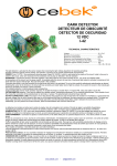
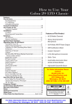
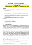
SPBS
REVERSING OBSTACLE SENSOR
ACHTERUIT RIJ SENSOR
DETECTEUR D’OBSTACLES EN
MARCHE ARRIERE
MANUAL
HANDLEIDING
MANUEL D’UTILISATION
BACK SONAR
REVERSING OBSTACLE SENSOR
BACK SONAR
Wiring instruction and user manual
1. Features
♦ You can feel safe and have peace of mind and convenience as you reverse your
vehicle.
♦ Easy parking in city area, especially for bumper to bumper situation (= reduce
parking time)
♦ Avoid accidentally hitting animals, people or damaging your vehicle due to
obstacles.
♦ Super wide detecting angle that prevent side impacting, convenient for parking in
garage.
♦ Modern design and compact size, using latest technology.
♦ Easy to upgrade your vehicle. No drilling required.
♦ Simple wiring and easy installation, result in a DIY (Do it yourself) product.
♦ The acoustic sensor adopted close, water and dust proof type to ensure reliable
detection.
TO OBTAIN THE BEST FUNCTIONAL RESULT OF THIS DEVICE,
PLEASE READ THIS MANUAL CAREFULLY
SPBS
3
BACK SONAR
2. Packing contents (refer to figure 1)
Item Description
1
Electronic Control Unit (ECU)
2
Sensor with 2 meter shielding
cable
3
Sensor with 3 meter shielding
cable
4
Buzzer with 1 meter PVC wires
5
Power line with 2 meter PVC
wires
Quantity Remark
1
With double-sided sticker
1
Attached 2 pin connector
1
Attached 2 pin connector
Attached 2 pin connector
Attached 4 pin connector (to
ECU) and 2 pin connector (to
Buzzer)
6
Parts bag
1 set
Including following Sub-items
6-1 Rubber pad
2
For sensor mounting buffer
6-2 Wire Pincers (gauge #18-22)
2
For connection between power
line provided and reversing
light wires
6-3 Wire band (black)
3
For wiring fix up
6-4 Wire band (clip type white)
3
For wiring fix up
6-5 Bracket
2
For sensor mounting (screwed
type)
6-6 Wire band (small white)
2
For sensor cable fix to bracket
6-7 Self-tapping screw 3 x 8mm
4
Screw on bracket to fix sensor
6-8 Self-tapping screw 4 x 10mm
8
Screw on bracket to bumper
6-9 Double side tape sticker
4
For sensors mounting (glued
type)
7
Wiring instruction & User manual
1
This manual
NOTE : for gluing type mounting, the items 6-5 to 6-8 are not necessary.
SPBS
1
1
4
BACK SONAR
SPBS
5
BACK SONAR
3. Installation and wiring
IMPORTANT : The mounting position of the sensors is very critical and directly
affects the performance of the system operation.
Mounting method 1 (Fix sensor with double-sided sticker)
Step 1 : Find out the place for mounting sensors, for a general vehicle the most
suitable mounting position is between the top of the bumper near the
reverse lights. Or mount the sensors on the bottom right and bottom
left of the boot cover (see Fig. 2A). Don’t mount the sensors in front of
the bumper. Determine the space between two sensors and the height
from the road surface.
Step 2 : Clean the place where the sensors will be mounted, slip the rubber pad
(part item 6-1) onto the sensor’s bottom then fix the sensors with strong
adhesive tape. Insert the lead cables through the gap between the car
body and boot cover into the vehicle (see Fig. 2B)
Step 3 : Determine the mounting position of the control unit and buzzer, taking
into account the cable length and space available, ensure you can hear
the buzzer from the driving compartment. Fix the control unit and
buzzer with strong adhesive tape.
NOTE : 1. We recommend this mounting type because it’s easier.
2. Glue the sensor on the boot cover at least 65cm above the road surface. If
the mounting surface is slant or not flat, please cut the extra adhesive
stickers and use them to flatten the mounting angle, keep the angle
strictly vertical and horizontal.
SPBS
6
BACK SONAR
Installation diagram 1 :
SPBS
7
BACK SONAR
Mounting method 2 (Fix sensor with bracket)
Step 1 : Assemble the sensor and bracket with self-tapping screw (part item 67) then tie up the cable on small holes on the bracket with wire band
(part item 6-6) (see Fig. 2E).
Determine the place for mounting sensors bracket, for a general vehicle
the most suitable mounting position for the sensor bracket is beneath
the bumper. Determine the space between the two sensors will be
mounted and the height from road surface (see Fig. 2F)
Step 2 : Clean the place where the sensor’s bracket / fix the sensor’s bracket
with self-tapping screw provided (part item 6-8). Insert the lead cables
through the gap between the car body and bumper to the drain hole
under the chassis or gap between the car body and boot into the
vehicle.
Step 3 : Determine the mounting position of the control unit and buzzer, takin g
into account the cable length and space available, ensure you can hear
the buzzer from the driving compartment. Fix them with strong
adhesive tape.
NOTE : 1. Do not apply great force to the sensor.
2. Do not mount the control unit and buzzer outside the car.
3. Mount the sensor and bracket on the bumper at least 30cm, above ground,
(the mounting bracket is bent upwards 45 degrees). If necessary, you can
bend the bracket to adjust the detection angle. (Prevent picking up the
road surface)
SPBS
8
BACK SONAR
Installation diagram 2 :
SPBS
9
BACK SONAR
Wiring guide (see wiring diagram (See Fig. 2I)
1. There are 3 female sockets on the control unit, the wiring between the power,
buzzer, sensors and control unit is as follows.
#1 Power & buzzer line connector (4pin)
Insert the 4-pin plug (part item 5) into the 4-pin socket on the electronic
control unit (ECU), and plug the 2-pin connector that is attached on another
side together with the buzzer’s 2-pin female housing ; the remaining "Red" and
"Black" wires must be wired as follows :
(Red)
"+" Terminal of power supply, connect to "Positive" wire of
reverse lights with wire pincer (part item 6-2)
(Black) "-" Terminal of power supply, connect to "Negative" wire of
reverse lights with wire pincer (part item 6-2)
#2 Sensor male connector (2-pin)
Plug 2-pin male connector of longer sensor cable (part item 3) into the one 2pin female socket on ECU.
#3 Sensor male connector (2 pin)
Plug 2-pin male connector of shorter sensor cable (part item 2) into the other
2-pin female socket on ECU.
NOTE : #2 and #3 connectors are interchangeable.
2. After the "Operation and Testing" procedures stated below, clean the entire wiring
loom and attach it with wire band.
SPBS
10
BACK SONAR
4. Operating and Testing
Step 1 :
(Ensure the electronic buzzer works)
After installation, move the vehicle to an area where there are no obstacles
within the range of the sensor. Start the vehicle’s engine and place the
transmission gear in "reverse" position. This means "switch ON the
system", the buzzer will beep once for approximately one second to
indicate that operation is normal. (The buzzer is mounted inside the boot)
NOTE :
1. To avoid discharging the car battery, do not turn the unit ON unless the
engine is running.
Step 2 :
(Verifying the system can produce different specific sounds when in the
proximity of an obstacle)
When the vehicle is within 90cm of an obstacle, the electronic buzzer will
beep slowly intermittently to indicate an obstacle is nearby. When an
obstacle is within 60cm, the buzzer will change to beeping quickly
intermittently and if it is within 40cm, the buzzer will beep continuously.
(See Fig.-4A)
NOTE :
1. Maintain a slow speed of less than 5 km/hour when close to an
obstacle.
2. When you hear the buzzer change from a quick beep to a continuous
beep, please step on the brake immediately to stop the vehicle.
3. When reversing, as soon as the vehicle comes to obstacle within 40cm,
the buzzer will start to "beep" continuously, this continuous beep will
remain even if the vehicle moves further away keeping within a rnage
of 90cm. This hysteresis function provides more safety than actually
required
4. Reversing the vehicle up or down a slope may cause a false alarm, but
it will also remind you to be careful in this situation. (See Fig. 3B &
Fig. 3C)
5. If you encounter problems during operation and testing, please refer to
the "Trouble shooting" table below.
6. When you have completed the above procedure, installation is
complete and the system is ready for use.
SPBS
11
BACK SONAR
N.B. :
This system is designed to assist drivers to judge situations behind their vehicle
when reversing. It is very important to note that the system is not intended to
replace the driver’s attention, and therefore can not be relied on to an excessive
degree. Please remember that ultimately, driving safety remains the sole
responsibility of the driver.
The system may not operate accurately and the sensing range may be narrowed in the
following situations :
(1) Very thin and small object such as pins and rope.
(2) Conical objects.
(3) Angular reflective objects.
(4) Cotton, snow and other obstacles that readily absorb sound waves.
(5) If the sensor element is covered by snow, ice, mud or other objects.
(6) When the sensor receives interference from other ultrasonic transmission.
(7) On irregular road surfaces, cobblestones, sloping streets and driving area
with weeds.
SPBS
12
BACK SONAR
5. Trouble shooting
Problem
The system works even
when the transmission
gear is not in "Reverse"
position
There is no buzzer sound
as the vehicle reverses
(The reverse light in ON)
Two short "beep" sounds
instead of the normal onesecond long "beep"
prompt sound as soon as
you change into reverse.
Three short "beep" sounds
instead of the normal onesecond long "beep"
prompt sound as soon as
you reverse the vehicle.
SPBS
Caused by
There are some mistakes
in the power line wiring
Solve the problem
Ensure the Red and Black
wire of the 4-pin power
line is connected to the
reverse light. That means
the system will be
switched ON only when
the vehicle is reversing.
1.Check the Red and
1. No power supply to
Black wire of the 4-pin
control unit.
plug with a multimeter
2. Bad connection between 2.Ensure good
conductivity between
buzzer and control unit
buzzer and control unit.
3.Replace the control unit
3. The control unit is
with a new one.
damaged.
1. Bad connection between 1.Pull out both sensor
plugs and insert each
one side sensor and
sensor separately to find
control unit.
out which side caused
the problem.
2.Ensure good
2. One side of sensor is
conductivity between
damaged.
plug and socket or if a
sensor is damaged,
replace it with a new
one.
1. Bad connection between 1.Inspect the wire harness
to check if wire is open.
sensors and control unit.
Plug out and plug in the
sensors socket on the
control unit to make sure
conductivity is good.
2.If one sensor or both are
2. Both sensors are
damaged then replace
damaged.
with a new one.
13
BACK SONAR
Problem
There are obstacles behind
the vehicle when
reversing, but the buzzer
sounds unstable.
The buzzer sound falsely
during vehicle reversing
when there is no obstacle.
The system always works
abnormally in certain
places, but OK in other
place.
Caused by
Solve the problem
1.Check the power, buzzer
1. Some of the wiring
and sensor conductivity
conductivity is not good.
with ECU.
2.Confirm the system is
2. Certain situations will
working in certain
cause this phenomenon.
situations stated in this
manual "6. Operation
N.B. item".
1. The sensor picks up the 1.Bend the bracket
upwards a little and try
road surface.
again, if possible move
the sensors higher.
2.Re-install the sensors
2. The sensors are not
securely.
installed securely.
3.Move the sensors to
3. As the sensors are
another location and try
installed on plastic, the
again.
cover causes resonance.
In this case, the system is
The sensor receives
OK, the interference
interference from other
source must be eliminated.
ultrasonic transmissions.
6. General specifications
* Working voltage range
* Power consumption
* Additional function
* System configuration
SPBS
:
:
:
:
9.6V - 16V
Less than 0.5W
Sensor Malfunction and system short indication
Double Sensor type
One control unit with two sensors
Detecting range : 90 ± 5 cm, 90°
90° spread for vertical and horizontal
14
BACK SONAR