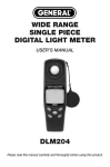
1
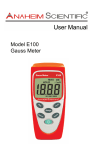
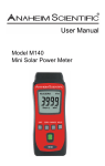
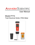
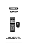
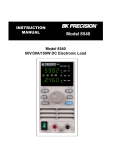
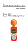
Models H115, H116, H117 Light, UVA, Solar Power Meters H117 Light, UVA, Solar Power Meter 1 Table of Contents 1 2 3 4 5 INTRODUCTION ................................................................................... 2 SAFETY SUMMARY............................................................................. 2 COMPLIANCE STATEMENTS ............................................................. 3 PRODUCT CONTENTS AND INSPECTION ........................................ 3 DEVICE DESCRIPTION ....................................................................... 5 5.1 DIAGRAM ........................................................................................... 5 5.2 LCD DESCRIPTION ............................................................................. 6 6 OPERATING PROCEDURES............................................................... 7 6.1 STARTING UP ...................................................................................... 7 6.2 ZERO ADJUSTMENT ............................................................................. 8 6.3 VIEWING AND SETTING THE CLOCK ........................................................ 8 6.1 AUTO RECORDING TIME SETUP........................................................... 9 6.2 VIEWING RECORDS .......................................................................... 10 6.3 MAX/MIN/AVG RECORD: ................................................................... 11 6.4 SINGLE DATA RECORD ..................................................................... 11 6.5 AUTO POWER OFF ........................................................................... 12 6.6 RELATIVE DEDUCTION VALUE(%) ...................................................... 12 6.7 BATTERY REPLACEMENT .................................................................. 13 7 TECHNICAL SPECIFICATIONS ........................................................ 14 7.1 GENERAL SPECIFICATIONS ............................................................... 14 7.2 SOLAR POWER SENSOR ................................................................... 14 7.3 UVA SENSOR .................................................................................. 15 7.4 LIGHT SENSOR ................................................................................ 15 7.5 RELATIVE SPECTRAL (SENSITIVITY) ................................................... 16 7.6 EXTERNAL DC POWER ..................................................................... 16 7.7 SYSTEM REQUIREMENTS .................................................................. 17 8 SOFTWARE INSTALLATION ............................................................ 17 9 MAINTENANCE .................................................................................. 19 10 SERVICE INFORMATION .................................................................. 19 10.1 SERVICE, REPAIR, OR CALIBRATIONS ................................................ 19 10.2 LIMITED TWO-YEAR WARRANTY ........................................................ 21 anaheimscientific.com Technical data subject to change without notice. ©Anaheim Scientific 2013, v20130726 2 1 Introduction Thank you for purchasing an H110 Series meter from Anaheim Scientific. With this meter you will have highly accurate results for Illumination (H117), Solar (H115,H117), or UVA (H116,H117) light measurements. Light and durable, the H110 Series meters will provide years of reliable service. The H110 Series applications include : Lighting for warehouses, factories, office buildings, restaurants, schools, library, and hospitals. Also photography, videography, building security, UV curing, suntan lighting, etc. The H100 Series features: 2 Convenient easy to read data displayed on the LCD screen Real time data Data hold function The H110 Series of light meters offers 3 Auto ranging models with different light sensors Back light Auto power off and disable auto power Model # Sensor off H115 Solar Power USB PC interface H116 UVA Data logging capacity up to 45,000 H117 Solar Power, UVA, and Light readings Low battery indicator Over load indicator Maximum/Minimum/Average record and elapse time Auto zero adjustment Safety Summary CAUTION Adhere to the following conditions for safe and effective usage of this meter • Operating altitude: Below 2,000m. • Do not store this device in direct sunlight or where it is hot and/or damp. anaheimscientific.com Technical data subject to change without notice. ©Anaheim Scientific 2013, v20130726 3 • Remember to turn OFF the power after use. For long storage, remove the battery to prevent the battery from leaking to cause damage to the parts inside. • Clean the device with a dry soft cloth. Wet cloths, liquid and water are prohibited. 3 Compliance Statements Caution: This symbol indicates that the equipment and its accessories are subject to special collection and disposal procedures • This tester was designed in accordance with EMC Standards in force and its compatibility has been tested in accordance with EN61326-1 (2006) • Meets JISC1609:1993 and CNS 5119 General Class A Specifications 4 Product Contents and Inspection This unit is tested prior to shipment. It is therefore ready for immediate use upon receipt. An initial physical inspection should be made to ensure that no damage has been sustained during shipment. Inspect the packing box on receipt for any external damage. If any external damage is evident, remove the instrument and visually inspect its case and parts for any damage. If damage to the instrument is evident, a description of the damage should be noted on the carrier’s receipt and signed by the driver or carrier agent. Save all shipping packaging for inspection. Forward a report of any damage to the agent through which the unit is procured. anaheimscientific.com Technical data subject to change without notice. ©Anaheim Scientific 2013, v20130726 4 Retain the original packing in case subsequent repackaging for return is required. Use of the original packing is essential. After the mechanical inspection, verify the contents of the shipment. The items included in this package are: • • • • • • • • H11X Meter Carrying case User’s Manual 9V Battery Mini USB 4P (Male) to USB A Type Cable Installation CD AC to DC 9v (300mA) power supply Solar sensor (H115); UVA Sensor (H116); Solar, UVA, Illumination Sensors (H117) anaheimscientific.com Technical data subject to change without notice. ©Anaheim Scientific 2013, v20130726 5 5 Device Description 5.1 Diagram 1. Sensor Input connector 2. LCD 3. Power Button 4. Backlight/Down Button 5. Hold/Up Button 6. ADJ/SET Button 7. MAX/AVG/Min Button 8. Time/MEM button 9. Record/ UNIT switch Button 10. External power DC 9V 11. USB interface 12. Sensor Probe input(+) 13. UVA Sensor 14. Illumination sensor 15. Solar Sensor anaheimscientific.com Technical data subject to change without notice. ©Anaheim Scientific 2013, v20130726 6 5.2 LCD description 1. Numeral reading value 2. Time unit (hour: minute: month: second) 3. Memory reading symbol 4. AVG symbol 5. W/m2, mW/cm2, µW/cm2 unit 6. [Btu/(h*ft2)] unit 7. Lux unit 8. % unit 9. FC unit 10. Adjustment symbol 11. Low battery symbol 12. Auto power-off symbol 13. Memory symbol 14. Set symbol anaheimscientific.com Technical data subject to change without notice. ©Anaheim Scientific 2013, v20130726 7 6 Operating Procedures 6.1 Starting Up • If changing the sensor, make sure the meter is off while changing. • Push “ ” button turn on the meter. Push “ ” button again to turn off the meter. • Hold “ ” button and push “ ” button to change the measuring unit. W/m2>> Btu (ft2*h)>> W/m2 or Lux>> Fc >>Lux W/m2: Btu/(ft2*h): Lux: Fc: Push “ ” button to lock display data on the LCD. Push “ to unlock. ” button again HOLD: anaheimscientific.com Technical data subject to change without notice. ©Anaheim Scientific 2013, v20130726 8 6.2 Zero Adjustment • Push “ ” button and attach the cap on the sensor. “0.00” will appear on the LCD. Make sure that the cap is attached on the sensor. • If the zero adjustment has not been made correctly, some digits will appear on the LCD instead of “0.00”, and the word “CAP” will also appear on the LCD to inform you that the cap is not completely covering the sensor. ADJ/CAP: 6.3 Viewing and Setting the Clock • Press button to see the Year, Month, Date, hour and Second. Press it again to keep changing through these values. • This meter’s clock uses 24-hour time setting. • Hold “ ” button and Push “ ” button to setup the clock. • Push “ ” or “ ” button to change digit • Push “ ” or “ ” to select the setting to adjust • And press “ • Hour: anaheimscientific.com ” button to skip from hour to day, and day to month, etc. day: Month: Technical data subject to change without notice. ©Anaheim Scientific 2013, v20130726 9 • Year: Sec: Minute: • Push “ ” button to store the setting. • Years allowable: 2000~2099. Display will show: 00 ~ 99 6.1 • Hold “ Push “ Auto Recording Time Setup ” button and push “ ” button to go into the setup mode. ” button again to go into Auto Recording Time Setup. Min: • Push “ ” or “ ” button to change digit • Push “ ” or “ ” to select the setting to adjust • Press “ ” button to skip from minute to hour and press“ ” button one more time, it will skip to second, etc. (Min→Hour →Sec). . • Hour: • Push “ anaheimscientific.com Sec: ” button to store the setting. Technical data subject to change without notice. ©Anaheim Scientific 2013, v20130726 10 • If you do not want to use auto power off, you can set auto power off time to be 00:00 00. • Maximum auto recording time: 23 hours 59 minutes 59 seconds. • Minimum auto recording time: 1 second. 6.2 Viewing Records • Hold “ ” button and Push “ ” button to view records. • • Push“ ” or “ ” button to scroll through the records. • Push“ ” to change between [Btu (ft2*h) >> W/m2 >>Btu (ft2*h)] Or [FC >> LUX >> FC) units. W/m2: Btu/(ft2*h): Lux: Fc: anaheimscientific.com Technical data subject to change without notice. ©Anaheim Scientific 2013, v20130726 11 • Push “ ” button to view the time data (H:M, M:D, year, sec). • H:M • Hold“ mode. 6.3 M:D ”button and push“ year sec ”button again to exit viewing records Max/Min/Avg Record: • Press “ ” key to show the current MAX, MIN, and AVG values. • Press “ ” key to switch to the next display. The display switches from MAX to MIN, MIN to AVG, and AVG to MIN. Follow the figure circles. • Press and hold “ ”key to disable this function. • The maximum storage is up to 99 minutes and 99 seconds. • Press and hold “ 6.4 ” button for more than 2 seconds to exit this mode. Single Data Record • Push “ ” button. The meter will save the current measured result, and REC will also appear on the LCD. anaheimscientific.com Technical data subject to change without notice. ©Anaheim Scientific 2013, v20130726 12 6.5 Auto Power Off • If you want disable auto power off, please hold “ ” button and push “ ” button, the auto power off symbol will not display on the LCD. • If you want enable auto power off please hold “ ” button and push “ ” button again. The auto power off symbol will display on the LCD. • Auto power off time is 30 minutes. 6.6 Relative Deduction Value(%) • Hold “ ” button and push “ ” button to save the current measured result. “100” will show at first. Then future measured results will be divided by the saved result and given as a percentage on the LCD. %: • The transmission percent = (second measured value/first measured value)x100 • Hold “ ” button and push “ anaheimscientific.com ” button again to exit REL mode. Technical data subject to change without notice. ©Anaheim Scientific 2013, v20130726 13 6.7 Battery Replacement WARNING If the symbol ” ” appears on the LCD, please replace the battery immediately • • • • Turn off the instrument. Open the battery cover and remove the battery Replace with a 9V battery Install the battery cover. anaheimscientific.com Technical data subject to change without notice. ©Anaheim Scientific 2013, v20130726 14 7 Technical Specifications 7.1 General Specifications General Specifications (H115, H116, H117) Battery Life Display Sampling Power Off Data Output Datalogging Capacity Power Dimensions Weight Current Consumption Sensor Length 7.2 Approximately 100 hours 3 ¾ LCD 4 times/second Manual by push button or auto shut off after approx. 30 minutes USB PC serial interface Up to 45,000 reading 9v battery or AC to DC Adaptor (9v/300mA) 130(L) x 56(W) x 38(H) mm 250g ≤10mA 1 meter Solar Power Sensor Solar Power Sensor (H115, H117) Measuring Range Resolution Accuracy Spectral Response Auto Measurement & Ranges anaheimscientific.com 40.00 W/m2, 400.0 W/m2, 2000 W/m2 [13 Btu/(h*ft2), 127 Btu/(h*ft2), 634 Btu/(h*ft2)] 0.01 W/m2, 0.1 W/m2, 1W/m2 [0.01 Btu/(h*ft2), 0.1 Btu(h*ft2), 1 Btu(h*ft2)] Typically within ± 10 W/m2 [ ±3 Btu/(h*ft2) ] or ±5%, whichever is greater in sunlight. Additional temperature induced error ±0.38 W/m2 / °C [ ±0.12 Btu/(h*ft2)/ °C] from 25°C 400 – 1100 nm 0.01 W/m2 ~ 2000 W/m2 [0.01 Btu/(h*ft2) ~ 634 Btu/(h*ft2)] Technical data subject to change without notice. ©Anaheim Scientific 2013, v20130726 15 7.3 UVA Sensor UVA Sensor (H116, H117) Range Resolution Accuracy Spectral Response Peak Sensitivity Wavelength Sensor 7.4 40.0 µW/cm2, 400 µW/cm2, 20 mW/cm2 0.1 µW/cm2, 1 µW/cm2, 0.01 mW/cm2 ± (4%.F.S + 2dgt) 320 – 400 nm 365 nm Photo diode & UVA color correction filter Light Sensor Light Sensor (H117) Sensor Measuring Range Resolution Accuracy Angle Deviation from Cosine Characteristics Spectral Response Peak Sensitivity Wavelength Auto Measurement & Ranges anaheimscientific.com Silicon photodiode and filter 40.00, 400.0, 4000, 40000, 400000 Lux 40, 400, 4000, 40000 Foot-candles 0.01, 0.1, 1, 10, 100 Lux ±3% (Calibrated to standard incandescent lamp 2856° K) 6% other visible light source 30° ±2% 60° ±6% 80° ±25% 400 – 1100 nm 550 nm 0.01 W/m2 ~ 2000 W/m2 [0.01 Btu/(h*ft2) ~ 634 Btu/(h*ft2)] Technical data subject to change without notice. ©Anaheim Scientific 2013, v20130726 16 7.5 Relative Spectral (Sensitivity) The deviation from the comparative standards for luminosity is determined by JIS standard C 1609-1993. Peak sensitivity wavelength: 550 nm . Typ. Ta=23°C 100 90 RELATIVE SENSITIVITY (%) 80 70 V(λ)* 60 50 40 30 M110 20 10 0 380 440 500 560 620 680 740 WAVELENGTH (nm) *CIE Luminosity Function 7.6 External DC Power • External AC to DC adapter: Voltage 9VDC (8~14 VDC Max) • Socket pin Positive, Ground Casing • External Diameter 5.5mm, internal Diameter 2.1 mm. anaheimscientific.com Technical data subject to change without notice. ©Anaheim Scientific 2013, v20130726 17 7.7 • • • • • 8 System Requirements CPU Pentium 1000MHZ. RAM SDRAM 256MB. Hard Disk 200MB. OS: Windows 2000, Windows XP. Display: 800×600, 256 colors. Software installation Please insert the CD into your PC to install the software. Please select PL-2032 Driver folder. Click twice on the PL-2303 Driver Installer to install the USB driver. anaheimscientific.com Technical data subject to change without notice. ©Anaheim Scientific 2013, v20130726 18 Now select the H117 Windows software folder to install the Light Meter program on your computer. Double-click on the Setup file. If you see the “unknown publisher” window, select yes. Take out the CD from PC after completing the installation of the desktop icon. Use the USB cable to connect the meter and computer according to the drawing. Select the desktop icon (Light Meter) and click twice on left key of the mouse to run the program. You should now see the LCD from your light anaheimscientific.com Technical data subject to change without notice. ©Anaheim Scientific 2013, v20130726 19 meter showing on the computer screen. If no digits appear on the light meter LCD (the one showing on the computer) then right click to Tools/Connect. You may also want to try manually turning on the light meter and/or reconnecting the USB. Once the LCD on the computer screen reflects what is showing on the actual meter, your program is running properly. Right click on the mouse to see your options. Select Tools/Download to access the data recorded on your meter. 9 Maintenance This is a precision instrument. To guarantee its performances be sure to use it or keep it stored within the suitable environmental conditions given in the Safety Summary and Technical Specifications. Be sure to turn it off after use. To store the instrument for an extended period of time, remove the batteries to avoid any damage to its inner components. 10 10.1 Service Information Service, Repair, or Calibrations • The following are instructions regarding policies for servicing, repairing or calibrating Anaheim Scientific products. Turnaround time is usually less than ten (10) working days unless expedited service is requested and pre-arranged. anaheimscientific.com Technical data subject to change without notice. ©Anaheim Scientific 2013, v20130726 20 • Send an email to [email protected] requesting an RMA number specifying your request for either service/repair and/or calibration with your product’s model number. • Once you receive a reply from [email protected], you will be asked to ship prepaid to the address below. Package the unit carefully using filler or bubble wrap, and if possible, ship in the original box. Ship each unit separately. (Anaheim Scientific is not responsible for any shipping damage that may occur.) • Include a packing list with each unit shipped stating what type of service is required and include the return shipping information: name, address and telephone number. • If the unit is in warranty, please provide the following: proof of purchase or copy of the original invoice. • If the unit is out of warranty, prepayment is required by Check, Money Order or Credit Card. • Return all merchandise to Anaheim Scientific with pre-paid shipping. The flat-rate repair charge for Non-Warranty Service does not include return shipping. Return shipping to locations in North American is included for Warranty Service. • For overnight shipments and non-North American shipping fees please contact Anaheim Scientific Anaheim Scientific ATTN: Service/Repair 22820 Savi Ranch Parkway Yorba Linda, CA 92887 www.anaheimscientific.com anaheimscientific.com Technical data subject to change without notice. ©Anaheim Scientific 2013, v20130726 21 10.2 Limited Two-Year Warranty • Scientific warrants to the original purchaser that its products and the component parts thereof, will be free from defects in workmanship and materials for a period of two years from date of purchase. • Anaheim Scientific will, without charge, repair or replace, at its option, defective product or component parts. Returned product must be accompanied by proof of the purchase date in the form of a sales receipt. • To help us better serve you, please complete the warranty registration for your new instrument via our website www.anaheimscientific.com • Exclusions: This warranty does not apply in the event of misuse or abuse of the product or as a result of unauthorized alterations or repairs. The warranty is void if the serial number is altered, defaced or removed. • Anaheim Scientific shall not be liable for any consequential damages, including without limitation damages resulting from loss of use. Some states do not allow limitations of incidental or consequential damages. So the above limitation or exclusion may not apply to you. • This warranty gives you specific rights and you may have other rights, which vary from state-to-state. anaheimscientific.com Technical data subject to change without notice. ©Anaheim Scientific 2013, v20130726 22 22820 Savi Ranch Parkway Yorba Linda, CA 92887 www.anaheimscientific.com © 2013 Anaheim Scientific anaheimscientific.com Technical data subject to change without notice. ©Anaheim Scientific 2013, v20130726