1
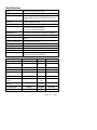
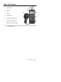
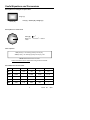
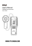
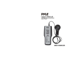
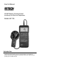
User's Manual
CFM Thermo Anemometer
Air Velocity, Air Flow, and Temperature
Model 407114
Introduction
Congratulations on your purchase of the Extech CFM Thermo Anemometer. This
meter measures Air Velocity, Air Flow and Temperature. An RS-232 PC
interface provides data acquisition functionality. Proper use of this meter will
provide years of reliable service.
Specifications
Circuit
Custom LSI microprocessor circuit
Display
Dual function 0.5" (13 mm) 4-digit (9999 count) LCD
Measurement units
Air Velocity: m/s, km/h, ft/min, knots, mph;
Air Flow: CMM (m3/min) and CFM (ft3/min);Temp: °C
and °F
Data hold
Freezes displayed reading
Sampling rate
1 second approx.
Sensors
Air velocity/flow sensor: Conventional angled vane
arms with low-friction ball bearing.
Temp. sensor: Precision thermistor
MAX/MIN Memory
Record and view Maximum and Minimum readings
Automatic Power off
Auto shut off after 15 minutes to preserve battery life
Data Output
RS 232 PC serial interface with 16-bit data stream
output
Operating Temperature
32°F to 122°F (0°C to 50°C)
Operating Humidity
Max. 80% RH
Power Supply
9V battery (Heavy duty alkaline)
Power Current
Approx. DC 8.3 mA
Weight
0.84 lbs. (381 g) including battery & probe
Dimensions
Main instrument: 7.1 x 2.8 x1.3" (180 x 72 x 32mm)
Sensor Head: 2.8” (72mm) diameter
Air Velocity
Range
Resolution Accuracy (%rdg)
m/s (meters per sec)
0.4 to 25.00 m/s
0.01 m/s
± (2% + 0.2 m/s)
km/h (kilometers per
hour)
1.4 to 90.0 km/h
0.1 km/h
±(2% + 0.2 km/hr)
ft/min (feet per minute)
80 – 4921 ft/min
1 ft/min
±(2% + 20 ft/min)
mph (miles per hour)
knots (nautical miles per
hour )
Air Flow/ Volume
0.9 – 55.9 mph
0.1 mph
± (2% + 0.2 mph)
0.8 to 48.6 knots
0.1 knots
± (2% + 0.2 knots)
Range
Resolution
Area
CMM (cubic meters per
minute)
0-999,900 m /min
0.001 to
100
0 to 9,999m2
CFM (cubic feet per
minute)
0-999,900 ft3/min
0.001 to
100
0 to 9,999ft2
Range
Resolution
Accuracy
o
1.5 oF (0.8 oC)
Air Temperature
3
o
o
32 - 122 F (0 - 50 C)
2
0.1 F/C
407114 V1.7
04/03
Meter Description
1.
LCD Display
2.
Keypad
3.
Sensor
4.
Sensor Input
5.
RS-232 PC Interface jack
6.
Protective rubber holster
7.
Battery compartment (rear)
Note: To access the rear battery compartment first remove the meter's rubber
protective holster.
3
407114 V1.7
04/03
Operation
Air Velocity Measurements
1.
Connect the sensor to the sensor input jack on top of the meter.
2.
Turn on the meter using the Power button.
3.
Select the VELOCITY function using the VEL/FLOW button. The LCD will
display “VEL” when the velocity mode is selected.
4.
Select the desired temperature units using the C/F select button. The LCD
will reflect the current unit selection.
5.
Select the desired air velocity units using the UNIT button. The LCD will
reflect the current unit selection.
6.
For maximum accuracy, the airflow must enter
the vane on the side without the yellow dot
(see diagram).
7.
View the air velocity and temperature readings
on the LCD Display. The large main LCD
display shows the Air Velocity reading. The
lower LCD sub-display shows the temperature
reading.
Side view of Vane
yellow
dot
airflow
Data Hold Feature
1.
While taking measurements, press the HOLD button to freeze the LCD
reading for later viewing.
2.
The “DH” indicator will appear on the LCD when the display is in Data Hold
mode.
3.
Press HOLD again to return to normal operation.
Maximum and Minimum Recording
The 407114 allows the user to record and view the highest (MAX) and lowest
(MIN) readings.
1.
Press the RECORD/RECALL button once. The “REC” indicator will appear
on the display and the meter will begin keeping track of the MAX and MIN
values.
2.
To view the MAX reading, press RECORD/RECALL again. The “MAX”
indicator along with the maximum reading will appear on the LCD display.
3.
Press RECORD/RECALL again to view the minimum value, the “MIN”
indicator along with the minimum reading will appear on the LCD display.
4.
To return to normal operation, press and hold the “RECORD/RECALL”
button for approx. 3 seconds. The display indicators REC, MAX, and MIN
will disappear.
4
407114 V1.7
04/03
Air Flow Measurements (CMM / CFM)
1. Connect the sensor to the sensor input jack on top of the meter.
2. Turn on the meter using the Power button.
3. Select the FLOW mode using the FLOW/VELOCITY button. The LCD will
display “FLOW” when the flow function has been properly selected.
4. Select the desired air flow units: CMM (cubic meters per minute) or CFM
(cubic feet per minute) using the UNIT button. The LCD will reflect the
selection.
2
2
5. Press the AREA button to begin entering the area in m or ft . Use the
button to increment the flashing digit, use the button to decrement the
flashing digit, use the button to select the next digit, and use the
RECORD/RECALL button to set the decimal point. Press the
ENTER/RESET button when the area has been entered. The bottom display
(normally used for the temperature display) will indicate the area entered in
2
2
ft or m . The main LCD displays the air flow in CFM (cubic feet per minute)
or CMM (cubic meters per minute). Refer to the Area Equations in the back of
this manual.
6. For air flow measurements, three modes apply: The normal, default mode,
where the actual flow is indicated, and the two modes described below: Press
the FLOW/MODE button to select one of the two modes listed below:
2/3V MAX MODE: LCD displays 2/3 the measured value.
AVG MODE: Up to 20 readings can be taken separately and averaged.
Select the AVG mode via the FLOW/MODE button and then press the
AVG/START button to take a reading. Up to 20 readings can be taken
and averaged. The lower LCD display provides a 1 to 20 counter and
each time a reading is taken the counter is incremented. The main LCD
displays the averaged air flow.
7. Note that the temperature function is not active in the AIR FLOW mode.
5
407114 V1.7
04/03
Battery Replacement
When the “LBT” icon appears on the LCD, the 9V battery must be replaced.
1. Remove the rubber holster that surrounds the entire meter
2. Slide off the rear battery compartment
3. Replace the 9V battery
4. Affix the battery compartment cover and the meter holster
RS-232 PC Interface
The 407114 is equipped with a 3.5mm phone jack (meter top) for connection to a
TM
PC for data acquisition purposes. To obtain PC interface cabling and Windows
data acquisition software, contact Extech Instruments. Instructions for use are
provided with the data acquisition software/hardware kits.
6
407114 V1.7
04/03
Warranty
EXTECH INSTRUMENTS CORPORATION warrants this instrument to be free of defects in parts and
workmanship for one year from date of shipment (a six month limited warranty applies on sensors and
cables). If it should become necessary to return the instrument for service during or beyond the warranty
period, contact the Customer Service Department at (781) 890-7440 ext. 210 for authorization or visit our
website at www.extech.com (click on ‘Contact Extech’ and go to ‘Service Department’ to request an RA
number). A Return Authorization (RA) number must be issued before any product is returned to Extech. The
sender is responsible for shipping charges, freight, insurance and proper packaging to prevent damage in
transit. This warranty does not apply to defects resulting from action of the user such as misuse, improper
wiring, operation outside of specification, improper maintenance or repair, or unauthorized modification.
Extech specifically disclaims any implied warranties or merchantability or fitness for a specific purpose and
will not be liable for any direct, indirect, incidental or consequential damages. Extech's total liability is limited
to repair or replacement of the product. The warranty set forth above is inclusive and no other warranty,
whether written or oral, is expressed or implied.
Calibration and Repair Services
Extech offers repair and calibration services for the products we sell. Extech also
provides NIST certification for most products. Call the Customer Service
Department for information on calibration services available for this product.
Extech recommends that annual calibrations be performed to verify meter
performance and accuracy.
Support Hotline (781) 890-7440
Tech support: Ext. 200; Email: [email protected]
Repair/Returns: Ext. 210; Email: [email protected]
Website: www.extech.com
Copyright © 2003 Extech Instruments Corporation
All rights reserved including the right of reproduction in whole or in part in any form.
7
407114 V1.7
04/03
Useful Equations and Conversions
Area equation for rectangular or square ducts
Height (H)
Area (A) = Width (W) x Height (H)
Width (W)
Area equation for circular ducts
Area (A) = 6 x r2
Where 6 = 3.14 and r2 = radius x
radius
Radius
Cubic equations
CFM (ft3/min) = Air Velocity (ft/min) x Area (ft2)
CMM (m3/min) = Air Velocity (m/sec) x Area (m2) x 60
NOTE: Measurements made in inches
must be converted to feet or meters before using the above formulae.
Unit of Measure Conversion Table
m/s
ft/min
knots
km/h
MPH
1
196.87
1.944
3.6
2.24
1 ft/min
0.00508
1
0.00987
0.01829
0.01138
1 knot
0.5144
101.27
1
1.8519
1.1523
1 km/h
0.2778
54.69
0.54
1
0.6222
1 MPH
0.4464
87.89
0.8679
1.6071
1
1 m/s
8
407114 V1.7
04/03