1
Internal CPU Board
Impact-E 40/41/50
User Manual
Preface
Copyright
This publication, including all photographs, illustrations and software, is protected under international
copyright laws, with all rights reserved. No part of this manual maybe reproduced, copied, translated or
transmitted in any form or by any means without the prior written consent from Amplicon Liveline Ltd.
Disclaimer
This Instruction Manual is supplied to provide the user with sufficient information to utilise the purchased
product in a proper and efficient manner. The information contained has been reviewed and is believed to be
accurate and reliable, however Amplicon Liveline Limited accepts no responsibility for any problems caused
by errors and omissions. Specifications and instructions are subject to change without notice.
Regulatory Compliance Statements
This section provides the FCC compliance statement for Class A devices and describes how to keep the
system CE compliant.
Federal Communications Commission (FCC) for Class A Device
This equipment has been tested and verified to comply with the limits for a Class A digital device, pursuant
to Part 15 of FCC Rules. These limits are designed to provide reasonable protection against harmful
interference when the equipment is operated in a commercial environment. This equipment generates, uses,
and can radiate radio frequency energy, and if not installed and used in accordance with the instructions,
may cause harmful interference to radio communications. Operation of this equipment in a residential area
(domestic environment) is likely to cause harmful interference, in which case the user will be required to
Impact-E 40 / 41 / 50 user manual
1
Preface
correct the interference (take adequate measures) at their own expense.
CE Certification
The product(s) described in this manual complies with all applicable European Union (CE) directives if it
has a CE marking. For computer systems to remain CE compliant, only CE-compliant parts may be used.
Maintaining CE compliance also requires proper cable and cabling techniques.
WARNINGS
Read and adhere to all warnings, cautions, and notices in this guide and
the documentation supplied with the chassis, power supply, and accessory
modules. If the instructions for the chassis and power supply are inconsistent
with these instructions or the instructions for accessory modules, contact
the supplier to find out how you can ensure that your computer meets
safety and regulatory requirements.
CAUTION
Electrostatic discharge (ESD) can damage NSA components. Do the
described procedures only at an ESD workstation. If no such station is
available, you can provide some ESD protection by wearing an antistatic
wrist strap and attaching it to a metal part of the computer chassis.
Safety Information
Before installing and using the CPU board, note the following precautions:
Read all instructions carefully.
Do not place the unit on an unstable surface, cart or stand.
Follow all warnings and cautions in this manual.
When replacing parts, ensure that your service technician uses parts specified by the manufacturer.
Avoid using the system near water, in direct sunlight or near a hearing device.
Impact-E 40 / 41 / 50 user manual
2
Preface
Table of Contents
Preface……………...……………..……………………………………….………….…………………..1
Copyright………………..……………………………………….…………………………………….... 1
Disclaimer………………………..………………………………..…………………………………….. 1
Acknowledgements……………………………………………..………………………………..…… 1
Regulatory Compliance Statements……………………..…………………………………………1
Federal Communications Commission (FCC) For Class A Device…………………..….....1
CE Certification……………………………………………………………………………………. 2
Safety Information…………………………………………………………………………………. 2
Table of Content……………………………………………………………………………………. 3
Chapter 1 General Information
1.1 Main Feature……………………………………………………………………………………….. 7
1.2 Specifications………………………………………………………………………………………. 7
1.3 Power Consumption Measurement……………………………………………………………… 10
1.4 Board Layout………………………………………………………………………………………11
1.5 Board Dimensions…………………………………………………………………………………12
Chapter 2 Jumper Setting
2.1 Before You Begin…………………………………………….……………………………………15
2.2 Precautions………………………………………………………………………………………... 15
2.3 Setting Jumpers…………………………………………………………………………………… 16
2.4 Location of Jumpers……………………………………………………………………………….17
2.5 Function of Jumper……………………………………………………………………………...... 18
2.6 Pin Definition……………………………………...………………………………………………15
Chapter 3 Expansion
3.1 System Memory…………………………………………………………………………………... 36
3.1 System Memory…………………………………………………………………………………... 37
3.2 Installing DIMM………………………………………………………………………………….. 38
3.3 Installing Compact Flash…………………………………………………………………………. 40
3.4 Installing Intel Pentium-M CPU and Fan Heatsink………………………………………………. 41
Chapter 4 Award BIOS Setup
4.1 About the BIOS…………………………………………………………………………………… 45
4.2 When to Run BIOS……………………………………………………………………………….. 45
4.3 Entering Setup……………………………………………………………………………………..46
4.4 The Main Menu……………………………………………………………………………………46
4.5 Getting Help………………………………………………………………………………………. 47
4.6 Control Keys……………………………………………………………………………………… 48
4.7 Standard CMOS Features………………………………………………………………………….49
Impact-E 40 / 41 / 50 user manual
3
Table Contents
4.8 Advanced BIOS Features…………………………………………………………………………. 51
4.9 Advanced Chipset Features……………………………………………………………………….. 53
4.10 Integrated Peripherals…………………………………………………………………………… 55
4.11 Power Management Setup………………………………………………………………………..57
4.12 PnP/PCI Configurations…………………………………………………………………………. 59
4.13 PC Health Status………………………………………………………………………………… 60
4.14 Load Fail-Safe Defaults…………………………………………………………………………. 60
4.15 Load Optimized Defaults………………………………………………………………………... 60
4.16 Set Password…………………………………………………………………………………….. 61
4.17 Save & Exit Setup……………………………………………………………………………….. 61
4.18 Exit Without Saving……………………………………………………………………………... 61
Appendix A Watchdog Timer
A.1 Watchdog Timer Working Procedure…………………………………………………………….. 63
A.2 Watchdog Timer Control Register………………………………………………………………...64
A.3 Watchdog Timer Programming Procedure……………………………………………………….. 65
Appendix B GPI/O Programming
B.1 GPI/O Programming……………………………………………………………………………... 67
Impact-E 40 / 41 / 50 user manual
4
Table Contents
Impact-E 40 / 41 / 50 user manual
5
Chapter 1
General Information
Impact-E 40 / 41 / 50 user manual
6
Chapter 1
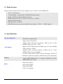
1.1 Main Feature
Supports Intel® Pentium® M/Celeron® M processor up to 2.0GHz+ with 400MHz FSB
•
•
•
•
•
•
•
Intel® 852GM chipsets
184-pin DIMM x 2, support Max. 2GB DDR 200/266 memory
Intel® 82551ER 10/100 Fast Ethernet LAN x 2
Display output via VGA x 1, DVI x 1or TV-out x 1, LVDS x 1
Internal Compact Flash x 1
USB 2.0 Port x 6, COM x 4
Mini-DIN 4-pin power connector with DC input voltage +12VDC ~ +30VDC support
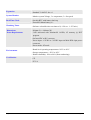
1.2 Specifications
System Architecture
CPU Support
Memory
BIOS
Impact-E 40 / 41 / 50 user manual
- Embedded computing board
- Single socket 478 uFCPGA
- Supports Intel® Pentium® -M processor: 1MB on die L2 Cache,
400MHz FSB, speed up to 1.7GHz
- Supports Intel® Dothan processor: 2MB on die L2 Cache, 400MHz
FSB, speed up to 2.0GHz
- Supports Intel® Celeron-M processor: 512KB on die L2 Cache,
400MHz FSB, speed from 600MHz
- On-board Intel® Micro-FCBGA 479-pin Pentium® -M/ULV/LV
Pentium® -M processor (option, with Min order Q'TY requirement)
- 184-pin DDR DIMM socket x 2 support un-buffered, non-ECC
DDR 200/266 up to 2 GB
- Plug & Play support
- Award System BIOS
- 4M bits flash ROM
- ACPI 1.0b compliant
7
Chapter 1
Chipset
- Intel® 82801DB x 1 I/O controller Hub (ICH4)
- Intel® 852GM
LAN
- Intel® 82551ER 10/100 Fast Ethernet LAN x 2
Display
- Intel® 852GM chipset integrated with graphics controller
- Up to 64MB of dynamic video memory allocation
- VGA: DB15 CRT VGA connector x 1, resolution support up to
1600 x 1200 @85Hz and up to 2048 x 1536 @ 75Hz
- LVDS: 44-pin connector x 1, support 18/24-bit single pixel or
18-bit dual pixel LVDS panel (resolution support up to 1400 x
1050)
- On-board Chrontel CH7009B DVI/TV out Transmitter x1
- DVI output: 34-pin box header x 1 for DVI 12bit interface,
resolution support up to 1600 x 1200
- TV-out: 7-pin mini-DIN for S-video TV-out interface
I/O Interface
Impact-E 40 / 41 / 50 user manual
- Serial port: One DB44 pin connector with one external cable for 4
COM ports with 16C550 UARTs (3 x RS232 + 1 x RS 232/422/485
via switch selection)
- USB: USB2.0 x 6 ports (4 ports in rear and 2 ports Front with 6-pin
JST 2.0mm 6-pin connector)
- LAN: 10/100 Fast Ethernet LAN x 2, RJ45 LAN port x 2
- HDD: 44-pin connector x 1, Ultra ATA33 support (Secondary)
- Internal Compact Flash socket x 1, support One Type II Compact
Flash card (Primary)
- Parallel port: bi-directional, EPP/ECP support, DB25 connector x 1
- FDD: supports standard 3.5" floppy drive via box header x 1
- External keyboard/ Mouse: 6-Pin Mini-DIn x 1
- Audio: AC'97 codec with MIC-in and speaker-out (2W amplified)
interface
- Digital I/O: 4-bit TTL input, 4-bit TTL output
- On-board buzzer x 1
- SP IrDA x 1
- On-board pin header for Power/HDD Access LED and Reset
8
Chapter 1
Expansion
- Standard 32-bit PCI slot x 1
System Monitor
- Monitor system Voltage, 3 x temperature, 3 x fan speed
Real Time Clock
- On-chip RTC with battery back up
- External Lithium battery x 1
Watchdog Timer
- Software selectable time-out interval (1~128 sec. 1~127 min.)
Dimensions
Power Requirements
- 260mm (L) x 180mm (W)
- 36W measured with Pentium-M 1.6GHz, 1G memory @ HCT
program
- On board DC to DC converter
- Power input: +12VDC to +30VDC input via Mini-DIN 4-pin power
connector
- Power mode: AT mode
Environments
- Board-level operating temperatures:-20°C to 60°C
- Storage temperatures: -20°C to 80°C
- Relative humidity: 10% to 90% (Non-condensing)
Certification
- CE
- FCC A
Impact-E 40 / 41 / 50 user manual
9
Chapter 1
1.3 Power Consumption Measurement
Test Configuration:
In Date: 10/19/2004
Out Date: 10/19/2004
BIOS Version: C-005
Configuration
Model Name
CPU Type/Speed/Model/Micro-Code
Intel Dothan 1.6GHz
Memory Type/Speed/Size/On-Board
Chip/Vendor
DDR/DDR333/1GB*2/SAMSUNG
Power Supply Type/Model/Watts-Value AT/Chroma 6210K-40
PS2 Keyboard and Mouse
Logitech Y-SJ17
Logitech M-S34
HDD Drive
WD WD400
DVD-ROM Devices
MSI C52 (MS-8152)
Floppy Drive
TEAC FD-235HF
Monitor
ViewSonic E70
Operation System
Windows2000 (English)-5.00.2195+SP4
Test Software / Program
HCT 9.5
Test Criteria:
1. Test configuration should include HDD drive, CD-ROM, FDD device.
2. Full loading mode should utilize CPU 100% with run HCT test program.
3. Light loading mode will utilize CPU loading below 5%, and there is no data or application
running.
Test Result:
CPU Type: Intel 1.6GHZ
DC Line 12V~30V: (System-Only)
12V
30V
Full-Loading Mode (A)
3.1
1.3
Light-Loading Mode (A)
2.2
1.0
Standby Mode (HDD Drive Power-Down) (A)
1.4
0.7
Impact-E 40 / 41 / 50 user manual
10
Chapter 1
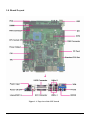
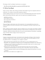
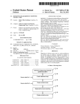
1.4 Board Layout
Figure 1.1: Top view of the CPU board
Impact-E 40 / 41 / 50 user manual
11
Chapter 1
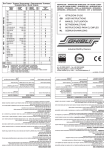
1.5 Board Dimensions
Figure 1.2: Mechanical Drawing of the CPU board
Impact-E 40 / 41 / 50 user manual
12
Chapter 1
Impact-E 40 / 41 / 50 user manual
13
Chapter 1
Chapter 2
Jumper Setting
Impact-E 40 / 41 / 50 user manual
14
Chapter 2
This chapter of the Users Manual describes how to set jumpers.
Note: The procedures that follow are generic for all CPU board series.
2.1 Before You Begin
Ensure you have a stable, clean working environment. Dust and dirt can get into components and cause a
malfunction. Use containers to keep small components separated.
Adequate lighting and proper tools can prevent you from accidentally damaging the internal components.
Most of the procedures that follow require only a few simple tools, including the following:
♦ A Philips screwdriver
♦ A flat-tipped screwdriver
♦ A set of jewelers Screwdrivers
♦ A grounding strap
♦ An anti-static pad
Using your fingers can disconnect most of the connections. It is recommended that you do not use
needle-nosed pliers to disconnect connections as these can damage the soft metal or plastic parts of the
connectors.
Before working on internal components, make sure that the power is off. Ground yourself before touching
any internal components, by touching a metal object. Static electricity can damage many of the electronic
components. Humid environments tend to have less st atic electricity than dry environments. A grounding
strap is warranted whenever danger of static electricity exists.
2.2 Precautions
Computer components and electronic circuit boards can be damaged by discharges of static electricity.
Working on computers that are still connected to a power supply can be extremely dangerous. Follow
the guidelines below to avoid damage to your computer or yourself:
♦ Always disconnect the unit from the power outlet whenever you are working inside the case.
♦ If possible, wear a grounded wrist strap when you are working inside the computer case. Alternatively,
discharge any static electricity by touching the bare metal chassis of the unit case, or the bare metal
body of any other grounded appliance.
♦ Hold electronic circuit boards (such as the CPU board) by the edges only. Do not touch the
components on the board unless it is necessary to do so. Do not flex or stress the circuit board.
♦ Leave all components inside the static-proof packaging that they shipped with until they are ready for
installation.
♦ Use correct screws and do not over tighten screws.
Impact-E 40 / 41 / 50 user manual
15
Chapter 2
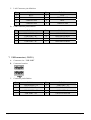
2.3 Setting Jumpers
A jumper is the simplest kind of electric switch. It consists of two metal pins and a cap. When setting the
jumpers, ensure that the jumper caps are placed on the correct pins. When the jumper cap is placed on
both pins, the jumper is SHORT. If you remove the jumper cap, or place the jumper cap on just one pin,
the jumper is OPEN. Please see the following illustrations
The illustrations on the right show
a 2-pin jumper. When the jumper
cap is placed on both pins, the
jumper is SHORT. If you remove
the jumper cap, or place the
jumper cap on just one pin, the
jumper is OPEN.
Open (Off)
Short (On)
These illustrations show a 3-pin
jumper. Pins 1 and 2 are SHORT.
Table 2-1: Setting Jumpers
Impact-E 40 / 41 / 50 user manual
16
Chapter 2
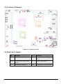
2.4 Location of Jumpers
Figure 2-1: Jumper Location
2.5 Function of Jumper
Pin
Function
Pin
Function
JP1
CMOS Status Select
JP7
DC Adapter Input Voltage
Select
JP4,JP3 COM4 RI# or Power Status
Select
J12
PANEL VDD Select
J5
SW1
COM2 RS232/422/485 Select
Pentium M FSB Select
Impact-E 40 / 41 / 50 user manual
17
Chapter 2
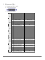
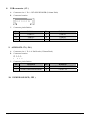
2.6 Pin Definition
1. IDE connector ( IDE1, IDE2 )
A.
B.
C.
Connector size:2 x 22 = 44Pins BOX Header, (2.0 mm Pitch)
Connector location:
2
44
{{{{{¨{{
{{{{¨{{
1
43
Connector pin definition
Pin
Definition
Pin
Definition
1
RSTDRV-
2
GND
3
IDED7
4
IDED8
5
IDED6
6
IDED9
7
IDED5
8
IDED10
9
IDED4
10
IDED11
11
IDED3
12
IDED12
13
IDED2
14
IDED13
15
IDED1
16
IDED14
17
IDED0
18
IDED15
19
GND
20
NC
21
IDEREQ-
22
GND
23
IDEIOW-
24
GND
25
IDEIOR-
26
GND
27
IDERDY
28
IDE-PD1
29
IDEACK-
30
GND
31
IDEIPQ
32
NC
33
DA1
34
66 DETECT
35
DA0
36
DA2
37
SCS1
38
SCS3
39
IDEACT-
40
GND
41
VCC5
42
VCC
43
GND
44
NC
Impact-E 40 / 41 / 50 user manual
18
Chapter 2
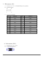
2. SIO connector ( J20A )
A.
B.
Connector size: 3 X 15 = 44 Pin
44 PIN D-SUB FEMALE
C.
Connector pin definition
Pin
COM1
COM2
(RS232)
COM3
COM4
Definition
Pin
Definition
1
DCD
2
RXD
3
TXD
4
DTR
5
GND
6
DSR
7
RTS
8
CST
9
RI
10
GND
11
DCD#: Data Carrier Detect.
12
RXD#: Receive Data
13
TXD: Transmit Data
14
DTR#: Data Terminal Ready
15
GND
16
DSR#: Data Set Ready
17
RTS#: Request To Send
18
CTS#: Clear To Send
19
RI#: Ring Indicator
(Could be a 5V or 12V Power pin)
20
GND
21
DCD
22
RXD
23
TXD
24
DTR
25
GND
26
DSR
27
RTS
28
CST
29
RI
30
GND
31
DCD
32
RXD
33
TXD
34
DTR
35
GND
36
DSR
37
RTS
38
CST
39
RI
40
GND
41
GP27IN
42
GP26IN
43
GP23OUT
44
GP22OUT
11
TXD-: Transmit Data Negative
12
TXD+: Transmit Data Positive
13
RXD+: Receive Data Positive
14
RXD-: Receive Data Negative
15
GND.DCD#: Data Carrier Detect
16
RTS-: Request To Send Negative
17
RTS#: Request To Send Positive
CTS-: Clear To Send Negative
(Could be a 5V or 12V Power pin)
18
CTS+: Clear To Send Positive
20
GND
GPIO
COM2
(RS422)
19
COM2
(RS485)
11
TXD-: Transmit Data Negative
RXD-: Receive Data Negative
12
TXD+: Transmit Data Positive
RXD+: Receive Data Positive
13
Reserved
14
Reserved
15
Reserved
16
Reserved
17
Reserved
18
Reserved
19
Reserved
(Could be a 5V or 12V Power pin)
20
GND
Impact-E 40 / 41 / 50 user manual
19
Chapter 2
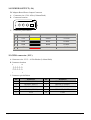
3. PIO connector ( J11 )
A.
B.
Connector size: 2 X 13 = 25 Pin BOX Header (2.0 mm Pitch)
Connector location
14
26
{ {… { {
{… { {
1
13
C.
Connector pin definition
Pin
Definition
Pin
Definition
1
STB#
14
AFD#
2
PD0
15
ERR#
3
PD1
16
PINIT#
4
PD2
17
SLIN#
5
PD3
18
GND
6
PD4
19
GND
7
PD5
20
GND
8
PD6
21
GND
9
PD7
22
GND
10
ACK#
23
GND
11
BUSY
24
GND
12
PE
25
GND
13
SLCT
26
N.C
4. VGA connector ( J21C )
A.
B.
Connector size: 3 X 5 = 15 Pin
15 PIN D-SUB FEMALE
Impact-E 40 / 41 / 50 user manual
20
Chapter 2
C.
Connector pin definition
Pin
Definition
Pin
Definition
1
RED
2
GREEN
3
BLUE
4
NC
5
GND
6
GND
7
GND
8
GND
9
KEY
10
GND
11
NC
12
ID1
13
HSYNC
14
HSYNC
15
ID3
5. Keyboard connector ( J21A )
A.
Connector size: Mini din 6 pins
B.
Connector location
6
4
3
2
C.
5
1
Connector pin definition
Pin
Definition
Pin
Definition
1
KBDAT
2
MSDAT
3
GND
4
VCC
5
KBCLK
6
MSCLK
6. LAN connector ( CON2/3/AB )
A. Connector size: RJ-45&USB PORT
B. Connector location:
Impact-E 40 / 41 / 50 user manual
21
Chapter 2
C.
D.
LAN Connector pin definition:
Pin
Definition
Pin
Definition
1
BTX+
2
BTX-
3
BRX+
4
TERM PLANE
5
TERM PLANE
6
BRX-
7
TERM PLANE
8
TERM PLANE
USB Connector pin definition
Pin
Definition
Pin
Definition
1
USB POWER +5V
2
USB PORT * D-
3
USB PORT * D+
4
GROUND POWER
5
USB POWER +5V
6
USB PORT * D-
7
USB PORT * D+
8
GROUND POWER
7. USB connector ( CON1 )
A.
B.
Connector size : USB PORT
Connector location:
C.
Connector pin definition
Pin
Definition
Pin
Definition
1
USB POWER +5V
2
USB PORT * D-
3
USB PORT * D+
4
GROUND POWER
5
USB POWER +5V
6
USB PORT * D-
7
USB PORT * D+
8
GROUND POWER
Impact-E 40 / 41 / 50 user manual
22
Chapter 2
8. USB connector ( J3 )
A.
B.
Connector size: 1 X 6 = JST 6PIN HEADER (2.00mm Pitch)
Connector location
○○○○○□
C.
Connector pin definition
Pin
Definition
Pin
Definition
1
USBVCC
2
USB1D-
3
USB1D+
4
USB2D-
5
USB2D+
6
USBGND
9. AUDIO CD- IN ( J16 )
A.
B.
Connector size: 1 X 4 = 4 Pin Header (2.54mm Pitch)
Connector location
{{{
1
C.
2 3 4
Connector pin definition
Pin
Definition
Pin
Definition
1
CD IN - L
2
AUDIO GROUND POWER
3
AUDIO GROUND POWER
4
CD IN – R
10. POWER ON/OFF ( JP5 )
Impact-E 40 / 41 / 50 user manual
23
Chapter 2
11. AUDIO LINE ( CON4B )
OUT PHONE JACK
AUDIO MIC IN (CON4A)
PHONE JACK
12. POWER INPUT ( JP6 )
DC Adapter Board Power Input Connector
13. POWER SUUPPLY ( J7 )
POWER SUUPPLY Power Input Connector
A.
B.
Connector size: 1X6 = 6 Pin ( 3.96mm Pitch )
Connector location
1
6
Connector pin definition
Pin
Name
Color
Description
1
+12V
Yellow
+12 VDC
2
GND
Black
Ground
3
GND
Black
Ground
4
GND
Black
Ground
5
+5V
Red
+5 VDC
6
+5V
Red
+5 VDC
Impact-E 40 / 41 / 50 user manual
24
Chapter 2
14. POWER OUTPUT ( J6 )
DC Adapter Board Power Output Connector
A.
B.
Connector size: 1X4= 4 Pin (3.96mm Pitch)
Connector location
4
C.
1
Connector pin definition
Pin
Name
Color
Description
1
+12V
Yellow
+12 VDC
2
GND
Black
Ground
3
GND
Black
Ground
4
+5V
Red
+5 VDC
15. GPIO connector ( J15 )
A. Connector size: 2 X 5 = 10 Pin Header (2.00mm Pitch)
B. Connector location
2
10
{{{{{
{{{{
1
9
C. Connector pin definition
Pin
Definition
Pin
Definition
1
GP27IN ( PIN20 )
2
GP23OUT ( PIN24 )
3
GP26IN ( PIN21 )
4
GP22OUT ( PIN25 )
5
GP25IN ( PIN22 )
6
GP21OUT ( PIN26 )
7
GP24IN ( PIN23 )
8
GP20OUT ( PIN27 )
9
VCC5
10
GND
Impact-E 40 / 41 / 50 user manual
25
Chapter 2
16. SMBUS connector ( J17 )
A. Connector size: 1 X 2 = 2 Pin Header (2.54mm Pitch)
B. Connector location
{{
1 2
C. Connector pin definition
Pin
Definition
Pin
Definition
1
SMBDATA
2
SMBCLK
17. FAN POWER connector ( FAN1,FAN2,FAN3 )
A. Connector size: 1 X 3 = 3PIN W/FAN (2.54mm Pitch)
B. Connector location
○○□
C. Connector pin definition
Pin
Definition
Pin
Definition
1
GND
2
+12V
3
Sensor
18. POWER ON & IDE & LAN Link/Active LED connector ( J1 )
A. Connector size: 2 X 7 = 13 Pin Header (2.54mm Pitch)
B. Connector location
2
12
{{{{{{
{{{{{{
1
13
Impact-E 40 / 41 / 50 user manual
26
Chapter 2
C. Connector pin definition
Pin
Definition
Pin
Definition
1
GND
2
ONLED
3
IDE Active
4
IDEACT#
5
SPEED_LAN1
6
LAN1_VCC
7
LILED_LAN1
8
ACTLED_LAN1
9
SPEED_LAN1
10
LAN2_VCC
11
LILED_LAN1
12
ACTLED_LAN2
13
NC
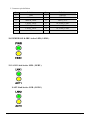
18. POWER ON & IDE Active LED ( LED1 )
19. LAN1 Link/Active LED ( LED2 )
LAN2 Link/Active LED ( LED3 )
Impact-E 40 / 41 / 50 user manual
27
Chapter 2
20. Hardware Reset connector ( J18 )
A. Connector size: 1 X 2 = 2 Pin Header (2.54 Pitch)
B. Connector location
1 2
{
C. Connector pin definition
Pin
Definition
Pin
Definition
1
GND
2
Reset
21. PCI1 - STANDARD PCI SLOT ( J10 )
STANDARD 5V / 32BIT / 33MHZ PCI SLOT
B62
B1
A62
A1
22. J8 – COMPACTFLASH SOCKET
(PRIMARY CHANNEL: DEFAULT MASTER)
50
49
26
1
23. TV-OUT ( J21B )
A. Connector size: MINI DIN 7PIN
B. Connector location
Impact-E 40 / 41 / 50 user manual
28
Chapter 2
C. Connector pin definition
Pin
Definition
1
VIDEO
2
GND
3
S-VIDEO
4
GND
5
S-VIDEO
6
GND
24. External thermal connector ( J19 )
A. Connector size: 1 X 2 = 2 Pin JST (2.5 Pitch)
B. Connector location
2 1
{
C. Connector pin definition
Pin
Definition
Pin
Definition
1
GNDA
2
External thermal Input
25. IRDA connector ( JP2 )
A. Connector size: 1 X 5 = 5 Pin Header (2.54mm Pitch)
B. Connector location
{{{{
1
5
C. Connector pin definition
Pin
Definition
1
VCC5
2
CIRRX
3
IRRX
4
GND
5
IRTX
26. CCFL connector ( J14 )
A. Connector size: 1 X 7 = 7 Pin JST (2.5 Pitch)
Impact-E 40 / 41 / 50 user manual
29
Chapter 2
B. Connector location
7 2 1
{{
…
C. Connector pin definition
Pin
Definition
Pin
Definition
1
VDD(5V or 3.3V)
5
GND
2
BACKLIGHT
6
GND
3
BACKLIGHT
7
BKLTCTL
4
BL_VR
27. Floppy connector ( J2 )
A. Connector size: 2 X 17 = 34 BOX Header (2.54mm Pitch)
B. Connector location
2
34
{{{{{¨{{
{{{{¨{{
1
33
C. Connector pin definition
PIN
Description
PIN
Description
1
Ground
2
Drive Density Select 0
3
Ground
4
NC
5
Ground
6
NC
7
Ground
8
Index Pulse Input
9
Ground
10
Motor On 0
11
Ground
12
Drive Select 1
13
Ground
14
Drive Select 0
15
Ground
16
Motor On 1
17
Ground
18
Step Direction
19
Ground
20
Step Pulse
21
Ground
22
Write Disk Data
23
Ground
24
Write Gate
25
Ground
26
Track 0
27
Ground
28
Write Protected
29
Ground
30
Read Disk Data
31
Ground
32
Head Select
33
Ground
34
Disk Change
Impact-E 40 / 41 / 50 user manual
30
Chapter 2
28. COM4 RI# or Power Status Select ( JP4,JP3 )
Pin
Status
Function Description
JP4 1-2
Short*
RI#
JP3 1-2
Short
Select +5V
JP3 2-3
Short
Select +12V
29. DVI ( J4 )
A. Connector size: 2 X 17 = 34 BOX Header (2.0mm Pitch)
B. Connector location
2
34
{{{{{¨{{
{{{{¨{{
1
33
C. Connector pin definition
PIN
Description
PIN
Description
1
Analog GND
2
Analog GND
3
T.M.D.S Data2-
4
T.M.D.S Data2+
5
GND
6
NC
7
NC
8
DDC Clock
9
DDC Data
10
NC
11
T.M.D.S Data1-
12
T.M.D.S Data1+
13
Analog GND
14
NC
15
NC
16
+5V
17
Analog GND
18
Hot Plug Detect
19
T.M.D.S Data0-
20
T.M.D.S Data0+
21
Analog GND
22
NC
23
NC
24
GND
25
T.M.D.S CLK+
26
T.M.D.S CLK-
27
GND
28
GND
29
NC
30
NC
31
NC
32
Analog GND
33
Analog GND
34
NC
Impact-E 40 / 41 / 50 user manual
31
Chapter 2
30. PANEL VDD Select ( J12 )
Pin
Status
Function Description
1-3;2-4
Short
VCC5
3-5;4-6
Short*
VCC3
31. External -12V Input connector ( J13 )
A. Connector size: 1 X 2 = 2 Pin JST (2.5 Pitch)
B. Connector location
2 1
{
C. Connector pin definition
Pin
Definition
Pin
Definition
1
-12V
2
GND
32. LVDS connector ( J20B )
A.
B.
Connector size: 3 X 15 = 44 Pin
44 PIN D-SUB FEMALE
C. Connector pin definition
Pin
Definition
Pin
Definition
Pin
Definition
1
DDCPCLK
16
DDCPDATA
31
GND
2
CLKBM
17
LCKBP
32
GND
3
YBM3
18
YBP3
33
GND
4
YBM2
19
YBP2
34
GND
5
YBM1
20
YBP1
35
GND
6
YBM0
21
YBP0
36
GND
7
CLKAM
22
LCKAP
37
GND
8
YAM3
23
YAP3
38
GND
9
YAM2
24
YAP2
39
GND
10
YAM1
25
YAP1
40
GND
11
YAM0
26
YAP0
41
VDD(5V or 3.3V)
12
BKLTCTL
27
VR
42
VDD(5V or 3.3V)
13
VDD(5V or 3.3V)
28
VDD(5V or 3.3V)
43
BACKLIGHT
Impact-E 40 / 41 / 50 user manual
32
Chapter 2
14
BACKLIGHT
29
BACKLIGHT
15
BACKLIGHT
30
BACKLIGHT
44
BACKLIGHT
PS: BACKLIGHT is backlight inverter Power
Marked “*” was the default setting.
33. COM2 RS232/422/485 Select ( SW1 )
Mode 1
RS232* OFF
RS422 OFF
RS485 ON
2
OFF
OFF
ON
3
OFF
ON
OFF
4
ON
OFF
ON
5
OFF
ON
ON
6
ON
OFF
OFF
7
OFF
ON
OFF
8
OFF
ON
OFF
9
OFF
ON
OFF
10
OFF
ON
ON
34. Pentium M FSB Select ( J5 )
Pin No.
Status
Function Description
1-3;2-4
Short*
400Mhz
3-5;4-6
Short
533Mhz
35. DC Adapter Input Voltage Select ( JP7 )
Pin No.
Status
Function Description
1-2
Short
8V-30V
2-3
Short*
12V-30V
36. CMOS Status Select ( JP1 )
Pin No.
Status
Function Description
1-2
Short*
Normal Operation
2-3
Short
Clear CMOS Data
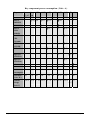
Power supply maximum watts and currents
Power Type
+12V 12V to +5V Total Watt
Consumed watts
48W
72.27W
120.27
4
14.45A
120.27
5
18
150
Consumed currents
(Item A )
Actually required currents (Item A/0.8 )
Impact-E 40 / 41 / 50 user manual
33
Chapter 2
Key component power consumption ( Unit : A )
Chipset
Vcore Vccp 1.35V +1.25V +1.5V +1.8V +2.5V +3.3V +5V +12v
0.7~1.7 1.05
Pentium M ▓25
▓0.5
INTEL
82852GM
▓2.4 ▓1.8
▓0.01 ▓0.32
▓0.05
DIMM X2
▓1.5
▓8
INTEL
ICH4
(82801B)
□
▓0.5
▓0.65
CLOCK
GEN.
(CK-408)
▓0.28
INTEL
82551ER
▓0.31
CH7009B
▓0.00
4
▓0.3
Super IO
( ITE8712)
▓1
Super IO
( ITE8710)
▓0.6
Other
▓2
▓4
2.4
1.8
1.51
0.824 0.5
8.05
4.14
1.89
1.24
20.13 13.66 5
25
Total
consumption
24.5
Transfer
Voltage
(Unit: V)
12 to 5 12 to 12 to 12 to 5 12 to 12 to 5 12 to 5 12 to 5 12 12
5
5
5
to 5
34
0.9
1 4
Total Watt
( Unit: W )
Impact-E 40 / 41 / 50 user manual
2.52 2.43
48
Chapter 2
Impact-E 40 / 41 / 50 user manual
35
Chapter 3
Expansion
Impact-E 40 / 41 / 50 user manual
36
Chapter 3
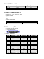
3.1 System Memory
Your system memory is provided by DIMMs (Dual In-Line Memory Modules) on the CPU board. The
board contains two memory banks: Bank 0 and 1, which correspond to connector DIMM1 and DIMM2.
The table below shows possible DIMM Configurations for the memory banks. Please note that the
CPU board supports Double Data Rate DDR 200/266/333/400 SDRAM. Configurations using different
brands of memory modules are not recommended.
DIMM1
DIMM2
Total Memory
128 MB
Empty
128 MB
Empty
128 MB
128 MB
128 MB
128 MB
256 MB
256 MB
Empty
256 MB
Empty
256 MB
256 MB
256 MB
256 MB
512 MB
512 MB
Empty
512 MB
Empty
512 MB
512 MB
512 MB
512 MB
1024 MB
1024 MB
Empty
1024 MB
Empty
1024 MB
1024 MB
1024 MB
1024 MB
2048 MB
Table 3-1: DIMM Configurations of the CPU board
Impact-E 40 / 41 / 50 user manual
37
Chapter 3
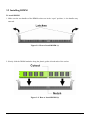
3.2 Installing DIMM
To install DIMM
1. Make sure the two handles of the DIMM sockets are in the “open” position, i.e. the handles stay
outward.
Figure3-1: How to Install DIMM (1)
2. Slowly slide the DIMM modules along the plastic guides in both ends of the socket.
Figure 3-2: How to Install DIMM (2)
Impact-E 40 / 41 / 50 user manual
38
Chapter 3
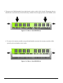
3. Then press the DIMM module down right into the socket, until a click is heard. That means the two
handles have automatically locked the memory modules into the right position of the DIMM socket.
Figure 3-3: How to Install DIMM (3)
4. To remove the memory module, just push both handles outwards, the memory module will be
ejected by the mechanism in the socket.
Figure 3-4: How to Install DIMM (4)
Impact-E 40 / 41 / 50 user manual
39
Chapter 3
3.3 Installing Compact Flash
1. To install a Compact Flash memory card into CPU board, align the notches on the card with the Compact
Flash socket in the CPU Board. Then firmly insert the card into the socket until it is completely seated.
Figure 3-5: How to Install Compact Flash Memory (1)
2. To remove the Compact Flash memory card from the CPU board, pull out the memory card from the
Compact Flash socket.
Figure 3-6: How to Uninstall Compact Flash Memory (2)
Impact-E 40 / 41 / 50 user manual
40
Chapter 3
3.4 Installing Intel Pentium-M CPU and Fan/Heatsink
Below is the installation instruction:
Note: Prepare a slot type screwdriver before starting the installation process.
Step1: Be sure that the beveled corner of the CPU as shown in the picture is aligned with that of the
socket.
Figure 3-7: How to Install CPU (1)
Step2: Screw it tight as shown in the picture.
Figure 3-8: How to Install CPU (2)
Impact-E 40 / 41 / 50 user manual
41
Chapter 3
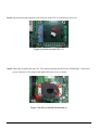
Step3: Apply the heatsink ointment to the location on the CPU as indicated by the arrow.
Figure 3-9: How to Install CPU (3)
Step4: Attach the heatsink onto the CPU. The exhaust opening should face the Northbridge. Connect the
power connector to the jumper and tighten the four screws as shown.
Figure 3-10: How to Install fan heatsink (1)
Impact-E 40 / 41 / 50 user manual
42
Chapter 3
Impact-E 40 / 41 / 50 user manual
43
Chapter 3
Chapter 4
Award BIOS Setup
Impact-E 40 / 41 / 50 user manual
44
Chapter 4
This chapter explains how to use the BIOS Setup program for the CPU board. The current BIOS setup pictures
in the chapter are for reference only, which may change by the BIOS modification in the future.
4.1 About the BIOS
The BIOS (Basic Input and Output System) Setup program is a menu driven utility that enables you to
make changes to the system configuration and tailor your system to suit your individual work needs. It is
a ROM-based configuration utility that displays the system’s configuration status and provides you with a
tool to set system parameters. These parameters are stored in non-volatile battery-backed-up CMOS
RAM that saves this information even when the power is turned off. When the system is turned back on,
the system is configured with the values found in CMOS.
With easy-to-use pull down menus, you can configure such items as:
♦ Hard drives, diskette drives, and peripherals
♦ Video display type and display options
♦ Password protection from unauthorised use
♦ Power management features
The settings made in the Setup program intimately affect how the computer performs. It is important,
therefore, first to try to understand all the Setup options, and second, to make settings appropriate for the
way you use the computer.
4.2 When to Run BIOS
This program should be executed under the following conditions:
♦ When changing the system configuration
♦ When a configuration error is detected by the system and you are prompted to make changes to
the Setup program
♦ When resetting the system clock
♦ When redefining the communication ports to prevent any conflicts
♦ When making changes to the Power Management configuration
♦ When changing the password or making other changes to the security setup
Normally, CMOS setup is needed when the system hardware is not consistent with the information
contained in the CMOS RAM, whenever the CMOS RAM has lost power, or the system features need to
be changed.
Impact-E 40 / 41 / 50 user manual
45
Chapter 4
4.3 Entering Setup
When the system is powered on, the BIOS will enter the Power-On Self Test (POST) routines. These
routines perform various diagnostic checks; if an error is encountered, the error will be reported in one of
two different ways:
♦ If the error occurs before the display device is initialized, a series of beeps will be transmitted.
♦ If the error occurs after the display device is initialized, the screen will display the error message.
Powering on the computer and immediately pressing <Del> allows you to enter Setup. Another way to
enter Setup is to power on the computer and wait for the following message during the POST:
TO ENTER SETUP BEFORE BOOT
PRESS <CTRL+ALT+DEL > KEY
Press the <Del> key or press the <Ctrl>, <Alt>, and <Esc> keys to enter Setup:
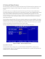
4.4 The Main Menu
Once you enter Award BIOS CMOS Setup Utility, the Main Menu (Figure 1) will appear on the screen.
The main menu allows you to select from ten setup functions and two exit choices. Use arrow keys to
select among the items and press <Enter> to accept or enter the sub-menu.
Figure 4-1: BIOS Setup Utility Main Menu
Impact-E 40 / 41 / 50 user manual
46
Chapter 4
Standard CMOS Features
Use this menu for basic system configuration.
Advanced BIOS Features
Use this menu to set the Advanced Features available on the system.
Advanced Chipset Features
Use this menu to change the values in the chipset registers and optimize the system’s performance.
Integrated Peripherals
Use this menu to specify your settings for integrated peripherals.
Power Management Setup
Use this menu to specify your settings for power management.
PnP/PCI Configurations
This entry appears if your system supports Plug and Play and PCI Configuration.
PC Health Status
Displays CPU, System Temperature, Fan Speed, and System Voltages Value.
Load Fail-Safe Defaults
Use this menu to load the BIOS default values for the minimal/stable performance for your system to
operate.
Load Optimized Defaults
Use this menu to load the BIOS default values, i.e., factory settings for optimal performance system
operations. While Award has designed the custom BIOS to maximize performance, the factory has the
option to change these defaults to meet their needs.
Set Password
Enables you to change, set, or disable the supervisor or user password.
Save & Exit Setup
Saves CMOS value changes to CMOS and exits setup
Exit Without Saving
Ignores all CMOS value changes and exits setup.
4.5 Getting Help
Main Menu
The on-line description of the highlighted setup function is displayed at the bottom of the screen.
Status Page Setup Menu/Option Page Setup Menu
Impact-E 40 / 41 / 50 user manual
47
Chapter 4
4.6 Control Keys
The table below lists the keys that help you navigate the setup program.
Up arrow
Move to previous item
Down arrow
Move to next item
Left arrow
Move to the item to the left
Right arrow
Move to the item to the right
Esc key
Main Menu: Quit without saving changes to CMOS
Status/Option Page Setup Menus: Exit current page and
return to Main Menu.
Enter Key
Select or Accept an Item
PgUp/plus key
Increase the numeric value or make changes
PgDn/minus key
Decrease the numeric value or make changes
F1 key
General help, only for Status Page Setup Menu and
Option Page Setup Menu
F2/Shift + F2 key
Change colour from total 16 colours. F2 to select colour
forward, (Shift) F2 to select colour backward
F5 key
Restore the previous CMOS value from CMOS (only
for Option Page Setup Menu)
F6 key
Load the default CMOS value from BIOS default table
(only for Option Page Setup Menu)
F7 key
Load the Setup default value (only for Option Page
Setup Menu)
F9 Key
Menu in BIOS
F10 key
Save all the CMOS changes (only for Main Menu)
Impact-E 40 / 41 / 50 user manual
45
Chapter 4
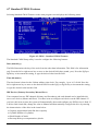
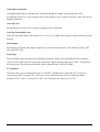
4.7 Standard CMOS Features
Selecting Standard CMOS Features on the main program screen displays the following menu:
Figure 4-2: BIOS – Standard CMOS Features
The Standard CMOS Setup utility is used to configure the following features:
Date (mm:dd:yy)
The BIOS determines the day of the week from the other data information. This field is for information
only. Press the left or right arrow key to move to the desired field (date, month, year). Press the PgUp or
PgDn key to increment the setting, or type the desired value into the field.
Time (hh:mm:ss)
The time format is based on the 24-hour military time clock. For example, 1 p.m. is 13:00:00. Press the
left or right arrow key to move to the desired field. Press the PgUp or Pg Dn key to increment the setting,
or type the desired value into the field.
IDE Devices (Primary/Secondary Master/Slave)
Your computer has two IDE channels (Primary and Secondary) and each channel can be installed with
one or two devices (Master and Slave). Use these items to configure each device on the IDE channel. If
you leave this item at Auto, the system will automatically detect and configure any IDE devices it finds. If
it fails to find a hard disk, change the value to Manual and then manually configure the drive by entering
the characteristics of the drive in the items below:
♦ Capacity Approximate hard disk drive capacity
♦ Cylinder Number of cylinders
♦ Head Number of heads
♦ Precomp Write pre-compensation cylinder
Impact-E 40 / 41 / 50 user manual
49
Chapter 4
♦ Landing Zone Landing zone
♦ Sector Number of sector
Refer to your drive’s documentation or look on the drive if you need to obtain this information. If no
device is installed, change the value to None.
Drive A
Select this field to the type of floppy disk drive installed in your system. The choices are:
♦ None: No floppy drive installed
♦ 360K, 5.25 in: 5-1/4 inch PC type standard drive; 360 kilobyte capacity
♦ 1.2M, 5.25 in: 5-1/4 inch AT-type high-density drive; 1.2 megabyte capacity
♦ 720K, 3.5 in: 3-1/2 inch double-sided drive; 720 kilobyte capacity
♦ 1.44M, 3.5 in: 3-1/2 inch double-sided drive; 1.44 megabyte capacity
♦ 2.88M, 3.5 in: 3-1/2 inch double-sided drive; 2.88 megabyte capacity
Note: The None option could be used for diskless workstations.
Video
Set this field to the type of graphics card installed in your system. If you are using a BGA or higher
resolution card, choose the EGA/VGA option. The options are:
♦ EGA/VGA Enhanced Graphics Adapter/Video Graphics Array. For EGA, VGA, SEGA or PGA
monitor adapters
♦ CGA40 Color Graphics Adapter, power up in 40 column mode
♦ CGA80 Color Graphics Adapter, power up in 80 column mode
♦ MONO Monochrome adapter, includes high resolution monochrome adapters
Halt On
During the Power-On Self-Test (POST), the computer stops if the BIOS detect a hardware error. This
setting determines which type of error will cause the system to halt during boot. The options are:
♦ All Error: Whenever the BIOS detects a non-fatal error, the system will be stopped and you will be
prompted.
♦ No Errors: The system boot will not stop for any error that may be detected.
♦ All, But Keyboard: The system boot will not stop for a keyboard error, but it will stop for all others.
After you have made your selections in the Standard CMOS Setup screen, press <ESC> to go back to the
main screen.
Impact-E 40 / 41 / 50 user manual
50
Chapter 4
4.8 Advanced BIOS Features
Selecting Advanced BIOS Feature on the main program screen displays this menu, which allows you to
define advanced information about your system. You can make modifications to most of these items to
improve your system performance or set up system features according to your preference, without causing
fatal errors to your system.
Figure 4-3: BIOS – Advanced BIOS Features
The following explains the options for each feature:
Virus Warning
Allows you to choose the Virus Warning feature for IDEHard Disk boot sector protection. If this function
is enabled and someone attempts to write data into this area, BIOS will show a warning message on
screen and an alarm will beep.
♦ Enabled: Activates automatically when the system boots up causing the following warning
message to appear when anything attempts to access the boot sector or hard disk partition table:
!WARNING!
Disk boot sector is to be modified
Type “Y” to accept write or “N” to abort write
Award Software, Inc.
♦ Disabled: No warning message will appear when an attempt is made to access the boot sector or
hard disk partition table.
Impact-E 40 / 41 / 50 user manual
51
Chapter 4
Note: This function is available only for DOS and other operating systems that do not trap INT13.
For complete protection against viruses, install virus software in your operating system and
update the virus definitions regularly.
Many disk diagnostic programs that access the boot sector table can trigger the virus warning
message. If you plan to run such a program, we recommend that you disable the virus
warning.
CPU L1, L2 and L3 Cache
Cache memory is an additional memory that is much faster than conventional DRAM (system memory).
This BIOS feature is used to enable or disable the processor's Level 1, Level 2 and Level 3 cache.
Naturally, the default and recommended setting is Enabled.
Note: This field will be available only if your CPU supports this function.
First/Second/Third Boot Device
BIOS attempts to load the operating system from the devices in the sequence selected. The available
choices are: Floppy, HDD-0, SCSI, CDROM, HDD-1, HDD-2, HDD-3, USB-FDD, USBZIP,
USB-CDROM, USB-HDD, LAN, and Disabled.
Boot Up NumLock Status
Toggle between On or Off to control the state of the NumLock key when the system boot. If On, the
numeric keypad is in numeric mode. If Off, the numeric keypad is in cursor control mode.
Gate A20 Option
Gate A20 refers to the way the system addresses memory above 1MB (extended memory). This feature
enables you to select whether the chipset or the keyboard controller should control Gate A20. The options
are:
♦ Normal: A pin in the keyboard controller controls Gate A20
♦ Fast : Let system chipsets control Gate A20. The fast setting improves system speed, particularly
with OS/2 and windows.
Security Option
Enables you to select whether the password is required every time the system boots or only when you
enter Setup.
♦ System: The system will not boot and access to Setup will be denied if the correct password is not
entered at the prompt.
♦ Setup: The system will boot, but access to Setup will be denied if the correct password is not entered
at setup.
Impact-E 40 / 41 / 50 user manual
52
Chapter 4
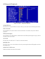
4.9 Advanced Chipset Features
Since the features in this section are related to the chipset in the CPU board and all are optimised, you are
not recommended to change the default settings in the setup table, unless you understand the chipset
features.
This section allows you to configure the system based on the specific features of the installed chipset.
This chipset manages bus speeds and access to system memory resources, such as DRAM and the external
cache. It also coordinates communications between the conventional ISA bus and the PCI bus. The
default settings have been chosen because they provide the best operating conditions for your system. The
only time you might consider making any changes would be if you discovered that data was being lost
while using your system.
The first chipset settings deal with CPU access to dynamic random access memory (DRAM). The default
timings have been carefully chosen and should only be altered if data is being lost. Such a scenario might
well occur if your system has mixed speed DRAM chips installed so that greater delays may be required
to preserve the integrity of the data held in the slower memory chips.
Selecting Advanced Chipset Features on the main program screen displays this menu:
Figure 4-4: BIOS – Advanced Chipset Features
System BIOS cacheable
Selecting Enabled allows caching of the system BIOS ROM at F0000h-FFFFFh, resulting in better
system performance. However, if any program writes to this memory area, a system error may result. The
available choices are Enabled, Disabled.
Impact-E 40 / 41 / 50 user manual
53
Chapter 4
Video BIOS Cacheable
Selecting Enabled allows caching of the video BIOS ROM at C0000h, resulting in better video
performance. However, if any program writes to this memory area, a system error may result. The choices:
Enabled, Disabled.
On-Chip VGA
By default, the On-Chip VGA or chipset-integrated VGA is Enabled.
On-Chip Frame Buffer Size
The On-Chip Frame Buffer Size can be set as 1, 4, 8, 16 or 32MB. This memory is shared with the system
memory.
Boot Display
Boot Display determines the display output device where the system boots. The options are Auto, CRT,
LFP, and CRT+LFP.
Panel Type
This field allows user to decide the LVDS panel resolution. Please refer to the BIOS for the resolution.
After you have made your selections in the Advanced Chipset Features setup, press <ESC> to go back to
the main screen. The options are 640x480 18bits, 800x600 18bis, 1024x768 18bits.
TV Standard
This item allows you to designate the type of colored TV standard to be used when a TV receiver is
connecting to the TV out port. If a TV receiver is not connected to the XL2, this setting should be
disabled. NTSC is for U.S. colored TVs; PAL is for European and other non-U.S. TVs.
Impact-E 40 / 41 / 50 user manual
54
Chapter 4
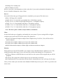
4.10 Integrated Peripherals
Figure 4-5: BIOS – Integrated Peripherals
OnChip IDE Device
Select this item to setup the IDE device features. When you select this item, the following menu shows:
USB 2.0 Controller
Select Enabled if your system contains a Universal Serial Bus 2.0 controller and you have USB 2.0
peripherals.
USB Keyboard Support
Select Enabled if your USB controller is enabled and it needs USB keyboard support in legacy (old) OS
operating systems such as DOS.
AC97 Audio
Selecting Auto will enable the AC’97 audio if it is detected onboard.
Init Display First
This feature allows you to select whether to boot the system using the onboard AGP graphics card or the
PCI graphics card.
Onboard LAN 1/2 H/W Active
Enables and disables the onboard LAN modules.
Impact-E 40 / 41 / 50 user manual
55
Chapter 4
Onboard FDC Controller
Select Enabled if your system has a floppy disk controller (FDC) installed on the system board and you
wish to use it. If you install an add-in FDC or the system has no floppy drive, select Disabled to this field.
Onboard Serial Ports (1, 2, 3, 4)
This feature allows you to manually select the I/O address and IRQ for the first and second serial ports. It
is recommended that you leave it as Auto so that the BIOS can select the best settings for it. But if you
need a particular I/O port or IRQ that's been taken up by this serial port, you can manually select an
alternative I/ O port or IRQ for it. You can also disable this serial port if you do not need to use it. Doing
so frees up the I/O port and IRQ used by this serial port. Those resources can then be reallocated for other
devices to use.
UART Mode Select
Select an operating mode for the serial port.
The choices are: Normal, IrDA, ASKIR.
UR2 Duplex Mode
In an infrared port mode, this field appears. Full-duplex mode permits simultaneous two-direction
transmission. Half-duplex mode permits transmission in one direction only at a time. Select the value
required by the IR device connected to the IR port.
Onboard Parallel Port
This feature allows you to select the I/O address and IRQ for the onboard parallel port. The default I/O
address of 378h and IRQ of 7 should work well in most cases. Unless you have a problem with the
parallel port, you should leave it at the default settings. The choices: 378/IRQ7, 278/IRQ5, 3BC/IRQ7,
and Disabled.
Parallel Port Mode
Select an operating mode for the onboard parallel (printer) port. There are four options: SPP (Standard
Parallel Port), EPP (Enhanced Parallel Port), ECP (Extended Capabilities Port) and ECP+EPP.
ECP Mode Use DMA
When the on-board parallel port is set to ECP mode, the parallel port can use DMA3 or DMA1.
Serial Port 3\4 Use IRQ
This assigns an IRQ to the serial port 3\4.
Impact-E 40 / 41 / 50 user manual
56
Chapter 4
4.11 Power Management Setup
This option lets you control system power management. The system has various power-saving modes
including powering down the hard disk, turning off the video, suspending to RAM, and software power
down that allows the system to be automatically resumed by certain events.
The power-saving modes can be controlled by timeouts. If the system is inactive for a time, the timeouts
begin counting. If the inactivity continues so that the timeout period elapses, the system enters a power
saving mode. If any item in the list of Reload Global Timer Events is enabled, then any activity on that
item will reset the timeout counters to zero.
If the system is suspended or has been powered down by software, it can be resumed by a wake up call
that is generated by incoming traffic to a modem, a LAN card, a PCI card, or a fixed alarm on the system
realtime clock. Selecting Power Management Setup on the main program screen displays this menu:
Figure 4-6: BIOS – Power Management Setup
ACPI Function
The ACPI standard (Advanced Configuration and power interface) allows the operating system directly to
check the functions of energy saving and the PnP (Plug and Play) functionality. The ACPI functions are
normally activated by the BIOS. The choices are: Enabled and Disabled.
Impact-E 40 / 41 / 50 user manual
57
Chapter 4
Video Off Method
This determines the manner in which the monitor is blanked. There are three choices:
1. V/H SYNC+Blank: This selection will cause the system to turn off the vertical and horizontal
synchronization port and write blanks to the video buffer.
2. Blank Screen: This option only writes blanks to the video buffer.
3. DPMS Support: Select this option if your monitor supports the Display Power Management signaling
(DPMS) standard of the Video Electronics Standard to select video power management values.
Video Off In Suspend
This determines the manner in which the monitor is blanked. The choices: Yes, No.
Suspend Mode
After the selected period of system inactivity, all devices except the CPU shut off. The choices are 1~2
min, 2~3 min,…. Up to 1 hour.
HDD Power Down
After the selected period of drive inactivity, the hard disk drive powers down while all other devices
remain active.
Wake up by PCI Card
When the system enters a Soft-off mode (Standby power exists but system is not working), it will wake
up system when specific signals occurred. The BIOS monitors the system for “activity” to determine
when to enable power management.
If you enable this feature, the computer specifies that any signal noticed on the PCI (Peripheral
Component Interconnect) bus channel must make go out from the hibernation state. The choices: Enabled,
Disabled.
Reload Global Timer Events
Primary/Secondary IDE 0/1
FDD, COM, LPT Port
PCI PIRQ [A-D]#
The events are I/O events whose occurrence can prevent the system from entering a power saving mode
or can awaken the system from such a mode. In effect, the system remains alert for anything, which
occurs to a device, which is configured as Enabled, even when the system is in a power down mode. The
choices are Enabled, and Disabled.
After you have made your selections in the Power Management setup, press the <ESC> key to go back to
the main program screen.
Impact-E 40 / 41 / 50 user manual
58
Chapter 4
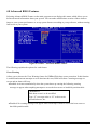
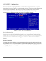
4.12 PnP/PCI Configurations
This section describes configuring the PCI bus system. Peripheral Component Interface, is a system
which allows I/O devices to operate at speeds nearing the speed the CPU itself uses when communicating
with its own special components. This section covers some very technical items and it is strongly
recommended that only experienced users should make any changes to the default settings.
Selecting PnP/PCI Configurations on the main program screen displays this menu:
Figure 4-7: BIOS – PnP/PCI Configurations
Reset Configuration Data
Normally, you leave this field Disabled, Select Enabled to reset Extended System Configuration Data
(ESCD) when you exit Setup if you have installed a new add-on Card and the system reconfiguration has
caused such a serious conflict that the operating system can not boot. The choices are Enabled and
Disabled.
Resources Controlled
The Award Plug and Play BIOS has the capacity to automatically configure all of the boot and Plug and
Play compatible devices. However, this capability means absolutely nothing unless you are using a Plug
and Play operating system such as going into each of the submenus that follows this field. The choices are
Auto (ESCD), Manual.
Impact-E 40 / 41 / 50 user manual
59
Chapter 4
4.13 PC Health Status
When main boards support hardware monitoring, this item lets you monitor the parameters for critical
voltages, critical temperatures, and fan speeds. These are the read only items.
After you have read the PC Health Status, press the <ESC> key to go back to the main program screen.
Figure 4-8: PC Health Status
4.14 Load Fail-Safe Defaults
This option opens a dialog box that lets you install fail-safe defaults for all appropriate items in the whole
setup utility. Press the <Y> key and then <Enter> to install the defaults. Press the <N> key and then
<Enter> to not install the defaults.
Use this option if you have changed your system and it does not operate correctly or does not power up.
4.15 Load Optimized Defaults
This option opens a dialog box that lets you install optimised defaults for all appropriate items in the
whole setup utility. Press the <Y> key and then <Enter> to install the defaults. Press the <N> key and
then <Enter> to not install the defaults. The optimized defaults place demands on the system that may be
greater than the performance level of the components, such as the CPU and the memory. You can cause
fatal errors or instability if you install the optimized defaults when your hardware does not support them.
If you only want to install setup defaults for a specific option, select and display that option, and then
press the <F7> key.
Impact-E 40 / 41 / 50 user manual
60
Chapter 4
4.16 Set Password
The User Password utility sets the password. The main board is shipped with the password disabled. If
you want to change the password, you must first enter the current password, then at the prompt enter your
new password. The password is case sensitive. You can use up to eight alphanumeric characters. Press
<Enter> after entering the password. At the next prompt, confirm the new password by retyping it and
pressing <Enter> again.
To disable the password dialog box appears. A message appears confirming that the password has been
disabled. If you have set supervisor and user Password, only the supervisor password allows you to enter
the BIOS setup program.
Note: If you forget your password, the only way to solve this problem is to discharge the CMOS
memory by turning power off and placing a shunt (jumper cap) on jumper JP2 to short pin 2
and pin 3 for five seconds, then putting the shunt back to pin 1 and pin 2 of JP2.
4.17 Save & Exit Setup
Selecting this option and pressing <Enter> will save the new setting information in the CMOS memory
and continue with the booting process.
4.18 Exit Without Saving
Selecting this option and pressing <Enter> will exit the Setup utility without recording any new values or
changing old ones.
Impact-E 40 / 41 / 50 user manual
61
Chapter 4
Appendix A
Watchdog Timer
Impact-E 40 / 41 / 50 user manual
62
Appendix A
The CPU board features a watchdog timer that reset the CPU or generates an interrupt if the processor
stops operating for any reason. This feature ensures system reliability in industrial standalone or
unmanned environments.
A.1 Watchdog Timer Working Procedure
The Watchdog Timer (WDT) is a special hardware device that monitors the computer system during
normal operation. The WDT has a clock circuit that times down from a set number to zero. If a monitored
item occurs before the timer reaches zero, the WDT resets and counts down again. If for some reason the
monitored item doesn’t occur before the timer reaches zero, the WDT performs an action, such as a
diagnostic operation (rebooting the computer) or generate an NMI.
You must enter timer values into the WDT Configuration Register (Write the control value to the
Configuration Port), and clear (read the Configuration Port).
WDT Configuration port
I/O port 2E0h
Read/Writable, default at 2E0h
Disable WDT functions (Default
setting)
Enable WDT functions controlled by WDT
Enabled
time out active for and WDT Time Out Active
Time
Reset Output
Reset system when WDT time out
NMI Output
Generate NMI when WDT time out
1. Located at J8 pin No. 6
2. Normal work output low level
WDT Notice Output 3. Output high level when WDT time-out,
read or write WDT configuration port return
to normal work (output low level)
1 sec/min
2 sec/min
4 sec/min
8 sec/min
WDT time out occurs after the selected time
16 sec/min
level
32 sec/min
64 sec/min
128 sec/min
Disabled
Watchdog Timer
WDT Time out active for
WDT Time Out Active Time
Table A-1: Watchdog Timer Character and Function
Impact-E 40 / 41 / 50 user manual
63
Appendix A
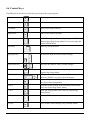
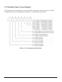
A.2 Watchdog Timer Control Register
The Watchdog Timer Control Register controls the EDT working mode. Write the value to the WDT
Configuration Port. The following table describes the Control Register bit definition.
Table A-2: Control Register Bit Definition
Impact-E 40 / 41 / 50 user manual
64
Appendix A
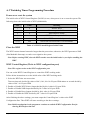
A.3 Watchdog Timer Programming Procedure
Power on or reset the system
The initial value of WDT Control Register (D4~D0) is zero, when power is on or reset the system. The
following shows the initial value of WDT (00000000b):
Bit
Value
Meaning
7
0
Disable WDT
6
0
Reset output is disable
5
0
NMI output is disable
4
0
WDT Notice output is disable
3
0
Select WDT count mode by second
2, 0,1
000
Select time-out occurs after 1 second/minute
Table A-3: WDT Control Register Initial Value
Clear the WDT
The WDT counter internal cannot be longer than the preset time; otherwise, the WDT generates a NMI
(Non Maskable Interrupt) or sends a reset signal to the system.
Note: Before running WDT, clear the WDT to make sure the initial value is zero before enabling the
WDT.
WDT Control Register (Write to WDT configuration port)
Note: This register writes to the WDT configuration port.
You can set the WDT Control Register to control the WDT working mode.
Follow below instructions to set the initial value of the WDT working mode.
1. Select the WDT time out occurs time
Time-out intervals decided by values of bit 2, bit 1, bit 0 in I/O port 2E0h minute or second decide by
values of bit 3 in I/O port 2E0h
2. Enable or Disable WDT Notice Output decided by bit 4 value in I/O port 2E0h
3. Enable or Disable NMI Output decided by bit 5 value in I/O port 2E0h
4. Enable or Disable Reset Output decided by bit 6 value in I/O port 2E0h
5. Enable or Disable the WDT decided by bit 7 value in I/O port 2E0h
After finishing the above settings, you must output the Control Register’s value to the WDT
Configuration Port. Then WDT will start according to the above settings.
Note: Build a mechanism in the program to continue to read the WDT Configuration Port for
clearing WDT before time out.
Impact-E 40 / 41 / 50 user manual
65
Appendix A
Appendix B
GPI/O Programming
Impact-E 40 / 41 / 50 user manual
66
Appendix B
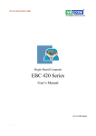
B.1 GPI/O Programming
GPI/O (General Purpose Input/Output) pins are provided for custom system design. This appendix
provides definitions and its default setting for the ten GPI/O pins. The pin definition is shown in
the following table:
Pin
No.
GPI/O mode
PowerOn
Default
Address
Pin
No.
GPI/O mode
PowerOn
Default
Address
1
GPI
Read High
801H (0)
2
GPO
High
801H (4)
3
GPI
Read High
801H (1)
4
GPO
High
801H (5)
5
GPI
Read High
801H (2)
6
GPO
High
801H (6)
7
GPI
Read High
801H (3)
8
GPO
High
801H (7)
9
VCC
-
-
10
GND
-
-
Table C-1: J15 – GPI/O Connector
Read the GPI Pin (1/3/5/7) status form I/O port 801H bit (0/1/2/3).
The bit is Set/Clear indicated High/Low
Control the GPO pin (2/3/6/8) level from I/O port 801H bit (4/5/6/7).
The bit is Set/Clear indicated output High/Low
Note: All of these GPIO pins are 8mA digital open-drain buffer and internal pull-up.
Impact-E 40 / 41 / 50 User Manual Part No. 85070155 Issue A1
67
Appendix B