1
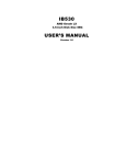
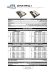
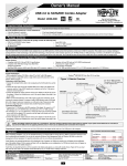
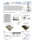
NISE 3120 AMD Geode Castle 400/500 Fanless +PC104 Plus RoHS User Manual 1 Copyright This publication, including all photographs, illustrations and software, is protected under international copyright laws, with all rights reserved. No part of this manual maybe reproduced, copied, translated or transmitted in any form or by any means without the prior written consent from NEXCOM International Co., Ltd. Version 1.0 Copyright 2006 Disclaimer The information in this document is subject to change without prior notice and does not represent commitment from NEXCOM International Co., LTD. However, users may update their knowledge of any product in use by constantly checking its manual posted on our website: http://www.nexcom.com. NEXCOM shall not be liable for direct, indirect, special, incidental, or consequential damages arising out of the use of any product, nor for any infringements upon the rights of third parties, which may result from such use. Any implied warranties of merchantability of fitness for any particular purpose is also disclaimed. Acknowledgements The EBC420 series is a trademark of NEXCOM international CO., LTD. All other product names mentioned herein are registered trademarks of their respective owners. Regulatory Compliance Statements This section provides the FCC compliance statement for Class A devices and describes how to keep the system CE compliant. Federal Communications Commission (FCC) For Class A Device This equipment has been tested and verified to comply with the limits for a Class A digital device, pursuant to Part 15 of FCC Rules. These limits are designed to provide reasonable protection against harmful interference when the equipment is operated in a commercial environment. This equipment generates, uses, and can radiate radio frequency energy and, if not installed and used in accordance with the instructions, may cause harmful interference to radio communications. Operation of this equipment in a residential area (domestic environment) is likely to cause harmful interference, in which case the user will be required to correct the interference (take adequate measures) at their own expense. CE Certification The product(s) described in this manual complies with all applicable European Union (CE) directives if it has a CE marking. For computer systems to remain CE compliant, only CE-compliant parts may be used. Maintaining CE compliance also requires proper cable and cabling techniques. 2 WARNINGS Read and adhere to all warnings, cautions, and notices in this guide and the documentation supplied with the chassis, power supply, and accessory modules. If the instructions for the chassis and power supply are inconsistent with these instructions or the instructions for accessory modules, contact the supplier to find out how you can ensure that your computer meets safety and regulatory requirements. CAUTION Electrostatic discharge (ESD) can damage NSA components. Do the described procedures only at an ESD workstation. If no such station is available, you can provide some ESD protection by wearing an antistatic wrist strap and attaching it to a metal part of the computer chassis. Safety Information Before installing and using the EBC573, note the following precautions: Read all instructions carefully. Do not place the unit on an unstable surface, cart, or stand. Follow all warnings and cautions in this manual. When replacing parts, ensure that your service technician uses parts specified by the manufacturer. Avoid using the system near water, in direct sunlight, or near a hearing device. Support For more information on this and other NEXCOM products, please visit our websites at: http://www.NEXCOM.com Product Warranty NEXCOM warrants to you, the original purchaser, that each of its products will be free from defects in materials and workmanship for one year from the date of purchase. This warranty does not apply to any products that have been repaired or altered by persons other than repair personnel authorized by NEXCOM, or which have been subject to misuse, abuse, accident or improper installation. NEXCOM assumes no liability under the terms of this warranty as a consequence of such events. Because of NEXCOM high quality-control standards and rigorous testing, most of our customers never need to use our repair service. If an NEXCOM product is defective, it will be repaired or replaced at no charge during the warranty period. For out-of-warranty repairs, you will be billed according to the cost of replacement 3 materials, service time and freight. Please consult your dealer for more details. If you think you have a defective product, follow these steps: Step 1.Collect all the information about the problem encountered. (For example, CPU speed, NEXCOM products used other hardware and software used, etc.) Note anything abnormal and list any onscreen messages you get when the problem occurs. Step 2.Call your dealer and describe the problem. Please have your manual, product, and any helpful information readily available. Step 3.If your product is diagnosed as defective; obtain an RMA (return merchandize authorization) number from your dealer. This allows us to process your return more quickly. Step 4.Carefully pack the defective product, a fully completed Repair and Replacement Order Card and a photocopy proof of purchase date (such as your sales receipt) in a shippable container. A product returned without proof of the purchase date is not eligible for warranty service. Step 5.Write the RMA number visibly on the outside of the package and ship it prepaid to your dealer. 4 Contents Chapter 1 Overview…………………………………………………….………………………………. 1.1 Introduction 1.2 Hardware Specifications 1.3 Safety Precautions 1.4 Chassis Dimensions 1.5 Packing list Chapter 2 Hardware Functionality………………………………………………………………. 2.1 Introduction Figure 2.1:Front panel Figure 2.2:Rear panel Chapter 3 Installation………………………………………………………………………………….. 3.1 Remove/install the Chassis 3.2 Remove/install the MINI PCI 3.3 Remove/install the Antenna 3.4 Remove/install the CompactFlashTM card 3.5 Remove/install the Memory 3.6 Remove/install the Hard disk Appendix A System I/O Address and Interrupt Assignment B Key components power consume C PCI Device interrupt and BUS Assignments D Connector Specification Figure C.1:EBC 420 E BIOS setting: How to enable Power on after Power failure 5 Chapter 1 Overview 1.1 Introduction Based on AMD Geode Castle processor and CS5536 chipset, the rugged NISE 3120 is designed for space-critical applications requiring fan-less operation, extreme reliability, low-power consumption and versatile I/O configuration. As such the NISE 3120 offers cost-effective solutions to a multitude of mission-critical embedded computing applications within automation, machine control, POS Systems and transportation. Housed in a compact 195mm x 150mm x 80mm heavy-duty aluminum chassis the NISE 3120's fan-less design makes for reliable, maintenance-free industrial computing. This versatile system gives users a wide variety of connection options with a myriad of I/O ports located at both the front and the rear of the unit. These include two 10/100 Ethernet LAN ports, four USB 2.0 ports, IEEE1394, VGA and Audio-out. For added flexibility, the NISE 3120 also boasts four RS232 ports, CompactFlash socket, PC104 plus and one min-PCI Expansion Slot for wireless connection solutions. The NISE 3120 supports DDR memory up to 1GB and one 2.5'HDD drive bay. 1.2 Hardware Specifications ∗ Memory:Support one 184-pin Non-ECC Non-Registered DDR DIMM Max up to 1GB ∗ Construction:Aluminum Chassis with FANless Design ∗ Dimension(W x D x H):195 x 150 x 80 mm ∗ Main board: --EBC420 --Support AMD Geode Castle 500 MHz with 128 KB L2 cache --AMD CS 5536 companion chip ∗ Device --On board Compact Flash socket x 1 --Internal 2.5”HDD Drive bay x 1 ∗ BIOS: ∗ I/O Port(Front) --HDD access/Power/LAN status LED (Act/Link; Speed) 6 --Programmable Alarm LED --Programmable Status LED --USB 2.0 x 4 ports --Serial port x 2 ∗ I/O Port(Rear) --Parallel port x 1 --PS/2 keyboard/mouse x 1 --IEEE1394 port x 1 --Serial port x 2 --Audio out x1 --10/100 Ethernet LAN x 2 --VGA connector x 1 --DC power +12V input x 1 ∗ Expansion Slot --PC/104 Plus (without -12V and -5V) --Mini-PCI Socket x 1 ∗ Power Supply --External 48W AC adapter x 1 --Power input: 100~240V AC 2A 50/60Hz --Power output: 12V DC ∗ Certification --CE approval --FCC ∗ Operating temperatures: --Ambient with air flow: 0°C to 40°C --NISE 3120 Tcase (Surface Temperature of Chassis) 5 °C ~ 40 °C (HDD) -10 °C ~ 45 °C (CF Card Only) ∗ Storage temperatures: -20°C to 80°C ∗ Relative humidity: 10% to 90% (Non-condensing) 1.3 Safety Precautions 7 The following sections tell how to make each connection. In most cases, you will simply need to connect a standard cable. Warning! Always disconnect the power cord from your chassis whenever you are working on it. Do not connect while the power is on. A sudden rush of power can damage sensitive electronic components. Only experienced electronics personnel should open the chassis. Caution! Always ground yourself to remove any static electric charge before touching NISE 3120. Modern electronic devices are very sensitive to static electric charges. Use a grounding wrist strap at all times. Place all electronic components on a static-dissipative surface or in a static-shielded bag. 8 1.4 Chassis Dimensions Figure 1-1: Chassis Dimensions 9 1.5 Packing List The accessory package of NISE 3120 contains of following items: 1. M/B BRACKET FOR NISE3120 2. FANLESS HEATSINK 3. CABLE, COM PORT. 9PINx2 TO HOUSING 4. HOLE PLUGS FOR NISE3120 5. IDE CABLE 6. PRINT CABLE 7. WALL MOUNT BRACKET 8. CHASSIS 9. IO BRACKET 10. EBC420 CD DRIVER 11. CABLE, Y PS/2 1 TO 2 KEYBOARD/MOUSE 12. DOW CORNING 340 Silicone Heat Sink Compound (3g) 13. EBC420 QUICK REFERENCE GUIDE 14. POWER ADAPTER 10 Chapter 2 Hardware 2.1 Introduction The following two figures show the connectors on NISE3120. The following sections give you detailed information about function of each peripheral. Figure2.1: Front panel of NISE3120 Figure2.2: Rear panel of NISE3120 11 12 Chapter 3 Installation In the follow pages, we will show you how to install (or remove) the cover and devices, including Antenna, MINI-PCI, Memory, CompactFlashTM card, Hard Disk and cables. Before the following action, please make sure you already remove the power cord. 3.1 Remove/ Install the Chassis [Top]Unscrew four screws from the top. [Bottom] Unscrew four screws from the bottom. [Front]Remove four screws from the front panel. [Rear]Remove four screws from the rear panel. [Side] 1. Remove top and bottom cover and the front and rear panel. 2. Unscrew four screws from the bracket 3. Remove the both side chassis. 13 3.2 Remove/ Install the MINI PCI NISE 3120 provide one MINI PCI card socket. You can use it to . Before you install (or remove) MINI-PCI Card, you must remove the Top Chassis first.(see chapter3.1) [install] Slowly slide the MINI PCI Card along the plastic guides in the both ends of the socket. [install] Press down the MINI PCI Card. [Remove] [Remove] The Mini PCI will jump up. Then you can remove it. 14 3.3 Remove/ Install the Antenna NISE3120 provide one Antenna. Before you install the Antenna, you must separate the Antenna and remove the top chassis first. Remove the Plug from the NISE 3120 rear panel. Then you can install your Antenna wire. 3.4 Insert/ Remove the Memory modules The NISE 3120 provides one DIMM memory socket. Before you install Memory modules, please make sure the two handles of the DIMM sockets are in the “open” position, and you must remove the top chassis first. [Insert] Slowly slide the DIMM modules along the plastic guides in the both ends of the socket. [Remove] Push the both handles outward, the memory module will be ejected by the mechanism in the socket. 15 3.5 Insert/ Remove the CompactFlashTM Card The NISE3120 provides one CompactFlashTM card socket. You can insert your CompactFlashTM Card directly. Before you insert the CF card, you must remove the bottom chassis first. [Insert] Slowly slide the CF card along the plastic guides in the both ends of the socket. [Remove] Pull out the memory card from the CF card socket. 3.6 Remove/ Install the Hard Disk The NISE3120 provides one IDE socket. Before you install the Hard Disk, you must remove the bottom and the side chassis first. Connect the IDE flat cable to the HDD. (pin1 is indicated in red). Connect the other side of the cable to IDE connector. (Pin1 is indicated in red). 16 Screw on the HDD in the bracket with four screws. 17 Appendix A: System Setting and Pin Assignments A.1 EBC 420 System I/O Ports A.2 EBC 420 Interrupt Assignment Interrupt No. Interrupt Source Interrupt No. Interrupt Source IRQ0 Timer IRQ1 KBC IRQ2 Cascade IRQ3 COM2 IRQ4 COM1 IRQ5 IR IRQ6 FDC IRQ7 LPT IRQ8 RTC IRQ9 Free (reserved for PCI) IRQ10 Free (reserved for PCI) IRQ11 COM3 IRQ12 PS/2 Mouse IRQ13 Math Co-processor IRQ14 IDE1 IRQ15 IDE2 ∗ Also have three On-board PCI IRQ and add on card IRQ be assigned, the IRQ resource be dynamic assigned by BIOS. 18 Appendix B: Key components power consume Vcore Vcore VTT +2.5 +3VS +5VS (CS553 +3.3V +3.3V (CPU) +1.25 V B B 6) LAN V +1.2V MEM +1.2V +5V +5V AUDIO Chipset 12V_ +12 IN V Castle □ □ □ □ □ CS5536 □ □ □ □ □ □ DIMM X 1 □ □ □ □ □ Clock Gen □ □ □ □ 1394A (VT6307S) □ □ □ LAN1 (RLT8110SB) □ □ LAN2 □ ((RLT8110SB) Mini-PCI 1.42 □ □ □ 0.16 0.1 □ □ 0.333 □ □ □ 0.182 □ □ □ □ 0.75 □ 4 □ □ □ □ □ □ □ □ □ □ □ □ □ □ □ □ □ □ 0.112 □ □ □ □ □ □ □ □ 0.41 □ □ □ □ □ □ □ □ □ □ □ 0.41 □ □ □ □ □ □ □ □ □ □ □ □ □ □ 0.475 0.1 □ PC/104-Plus □ 1 □ □ □ □ □ □ □ □ 3 2 □ AC97 (VT1616A) □ □ □ □ □ □ □ □ □ □ 0.038 □ 0.052 Super IO ( ITE8712) □ □ □ 0.1 □ □ □ □ □ □ □ 0.6 □ Super IO ( ITE8710) □ □ □ □ □ □ □ □ □ □ 0.6 □ □ IDE □ □ □ □ □ □ □ □ □ □ □ 1.5 □ Compact flash □ □ □ □ □ □ □ □ □ □ □ 0.1 □ USB x 4 □ □ □ □ □ □ □ □ □ □ □ 2 □ Other □ □ □ □ 0.1 □ □ □ □ □ □ □ □ 4.16 4.34 6.3 0.052 Total Consumption 1 0.1 0.1 1.42 0.333 0.75 0.82 Total Watt (Unit: W) 12 0.33 0.5 1.7 0.4 0.94 2.659 10.4 Transfer Voltage From (Unit: V) 12V_ +12 +1 12V_I 12V_I +12V +12V IN V 2V N N +12V +12V 14.32- 31.50.26 9.9 10-10 +12 +12V V +12V +12V All consumption Power Type Consumed watts +12V_IN +12V TOTAL NISE3120 75 74 75 44 Consumed currents (Item A ) 6.25 6.17 6.25 3.67 Actually required currents (Item A/0.85 ) 7.82 7.71 7.82 4.58 19 [Appendix C] PCI Device interrupt and BUS Assignments Chipset Configure BUS / Device/ PCI INT# REQ# / GNT# to Special feature description Function IT8209R AMD Geode Castle 0 / 1 / 1 Host-Hub Interface Bridge AMD CS5535/5536 0 /15/ 4,5 USB 1.1/2.0 Controller VT6307S 0 / 11 /0 D 2 to 1 1394A VT6105 0 / 12 /0 C 1 to 1 10/100 LAN VT6105 0 / 13 /0 B 1 to 2 10/100 LAN MINI-SPCI 0 / 14 /0 A 1 to 3 PC104-Plus 0 / 18 /0 A 2 to 2 20 [Appendix D] EBC 420 Connector Specification Audio Out J1 J2 J3 LAN2 LAN1 VGA 5 14 J4 1 1 1 1 Power connector (CON1) KB/MS 1394 a J6 1 1 J14 Parallel port(JP2) 1 39 TL Panel (CN4) Mini-PCI Socket (CN1) PA30 PA1 PC104+ (J10) 1 J13 PD30 92 91 184 183 LED 1 2 1 94 93 DIMM JP1 1 1 1 LED 3 LED 2 Power Button (SW1) J7 J8 COM1(J9) USB1 COM 2(J11) USB2 LED 4 FigureD.1: Main Board-EBC 420 D-1 IDE connector ( IDE1) A. Connector size:2 x 22 = 44Pins BOX Header, ( 2.0 mm Pitch ) B. Connector pin definition Pin Definition Pin Definition 1 RSTDRV- 2 GND 3 IDED7 4 IDED8 5 IDED6 6 IDED9 7 IDED5 8 IDED10 9 IDED4 10 IDED11 11 IDED3 12 IDED12 13 IDED2 14 IDED13 21 15 IDED1 16 IDED14 17 IDED0 18 IDED15 19 GND 20 NC 21 IDEREQ- 22 GND 23 IDEIOW- 24 GND 25 IDEIOR- 26 GND 27 IDERDY 28 IDE-PD1 29 IDEACK- 30 GND 31 IDEIPQ 32 NC 33 DA1 34 66 DETECT 35 DA0 36 DA2 37 SCS1 38 SCS3 39 IDEACT- 40 GND 41 +5V 42 +5V 43 GND 44 NC D-2 AUDIO LINE- IN ( J1 )/ AUDIO MIC- IN ( J2 )/ AUDIO CD- IN ( J3 ) A. Connector size: 1 X 4 = 4 Pin Header ( 2.54mm Pitch ) B. Connector pin definition J1 J2 Pin Definition J3 Pin Definition Pin Definition 1 LINE IN - R 1 MIC_BIAS 1 CD - L 2 AUDIO GROUND 2 AUDIO GROUND 2 AUDIO GROUND 3 AUDIO GROUND 3 AUDIO GROUND 3 AUDIO GROUND 4 LINE IN – L 4 MIC_IN 4 CD – R D-3 Serial Ports connector A. Connector size: 2 X 5 = 9 Pin B. Connector location and pin definition 9 PIN D-SUB MALE:COM1-2 ( J9,J11) PIN HEADER connector COM3-4 ( J4) Pin Definition Pin Definition 1 DCD 2 RXD 3 TXD 4 DTR 5 GND 6 DSR 7 RTS 8 CST 9 RI D-4 SMBUS connector ( J7 ) A. Connector size: 1 X 2 = 2 Pin Header ( 2.54mm Pitch ) 22 B. Connector definition Pin Definition 1 SMBDATA 2 SMBCLK D-5 Hardware Reset connector ( J8) A. Connector size: 1 X 2 = 2 Pin Header ( 2.54 Pitch ) B. Connector pin definition Pin Definition 1 GND 2 Reset D-6 PC-104 PLUS connector ( J10~PCI only 3.3v Device ) A. Connector pin definition Pin Description Description Description Description A B C D 1 Gnd/5.0V KEY Reserved +5V AD00 2 VI/O AD02 AD01 +5V 3 AD05 Gnd AD04 AD03 4 C/BE0# AD07 Gnd AD06 5 Gnd AD09 AD08 Gnd 6 AD11 VI/O AD10 M66EN 7 AD14 AD13 Gnd AD12 8 +3.3V C/BE1# AD15 +3.3V 9 SERR# GND SB0# PAR 10 Gnd PERR# +3.3V SDONE 11 STOP# +3.3V LOCK# Gnd 12 +3.3V TRDY# Gnd DEVSEL# 13 FRAME# Gnd IRDY# +3.3V 14 Gnd AD16 +3.3V C/BE2# 15 AD18 +3.3V AD17 Gnd 16 AD21 AD20 Gnd AD19 17 +3.3V AD23 AD22 +3.3V 18 IDSEL0 Gnd IDSEL1 IDSEL2 19 AD24 C/BE3# VI/O IDSE;3 23 20 Gnd AD26 AD25 Gnd 21 AD29 +5V AD28 AD27 22 +5V AD30 Gnd AD31 23 REQ0# Gnd REQ1# VI/O 24 Gnd REQ2# +5V GNT0# 25 GNT1# VI/O GNT2# Gnd 26 +5V CLK0 Gnd CLK1 27 CLK2 +5V CLK3 Gnd 28 Gnd INTD# +5V RST# 29 +12V INTA# INTB# INTC# 30 -12V Reserved Reserved Gnd/3.3V KEY D-7 1394A connector ( J12 ) A. Connector size : 1394 PORT B. Connector location and pin definition Pin Definition Pin Definition 1 +12V 2 GNDA 3 XTPB0M 4 XTPB0P 5 XTPB1M 6 XTPB1P D-8 FAN POWER connector ( J14 ) A. Connector size: 1 X 3 = 3PIN W/FAN ( 2.54mm Pitch ) B. Connector pin definition Pin Definition 1 GND 2 +12V 3 Sensor D-9 COMPACTFLASH SOCKET(J15) PRIMARY CHANNEL : Default MASTER 50 49 26 1 24 D-10 GPIO connector ( JP1) A. Connector size: 2 X 5 = 10 Pin Header (2.00mm Pitch) B. Connector pin definition Pin Definition Pin Definition 1 GP27IN ( PIN20 ) 2 GP23OUT ( PIN24 ) 3 GP26IN ( PIN21 ) 4 GP22OUT ( PIN25 ) 5 GP25IN ( PIN22 ) 6 GP21OUT ( PIN26 ) 7 GP24IN ( PIN23 ) 8 GP20OUT ( PIN27 ) 9 +5V 10 GND D-11 PIO connector ( JP2 ) A. Connector size: 2 X 13 = 25 Pin BOX Header ( 2.0 mm Pitch ) B. Connector location and pin definition Pin Definition Pin Definition 1 STB# 14 AFD# 2 PD0 15 ERR# 3 PD1 16 PINIT# 4 PD2 17 SLIN# 5 PD3 18 GND 6 PD4 19 GND 7 PD5 20 GND 8 PD6 21 GND 9 PD7 22 GND 10 ACK# 23 GND 11 BUSY 24 GND 12 PE 25 GND 13 SLCT 26 N.C D-12 POWER INPUT ( JP3 ):+12V DC Adapter Board Power Input Connector 25 D-13 VGA connector ( VGA1 ) A. Connector size: 3 X 5 = 15 Pin B. Connector location and pin definition-15 PIN D-SUB FEMALE Pin 1 6 11 5 10 15 Definition Pin 2 Definition 1 RED GREEN 3 BLUE 4 NC 5 GND 6 GND 7 GND 8 GND 9 KEY 10 GND 11 NC 12 ID1 13 HSYNC 14 VSYNC 15 ID3 D-14 Key board connector ( KB_MSA1 ) A. Connector size: Mini din 6 pins B. Connector location and pin definition 6 4 Pin 5 3 2 1 Definition Pin Definition 1 KBDAT 2 MSDAT 3 GND 4 +5V 5 KBCLK 6 MSCLK D-15 LAN connector (LAN1/2 ) A. Connector size: RJ-45 B. Connector location and pin definition Pin Definition Pin Definition 1 TX+ 2 TX- 3 RX+ 4 LAN1 5 LAN1 6 RX- 7 LAN2 8 LAN2 9 LAN Speed LED 10 Vcc3 LAN Link LED 12 LAN ACT LED# 11 26 D-16 USB connector ( USB1/2 ) A. Connector size : USB PORT B. Connector location and pin definition Pin Definition Pin Definition 1 USB POWER +5V 2 USB PORT * D- 3 USB PORT * D+ 4 GROUND POWER 5 USB POWER +5V + 6 USB PORT * D- 7 USB PORT * D+ 8 GROUND POWER D-17 POWER ON & IDE Active & LAN/link/ Active & Alarm & Status LED connector (LED1/2/3/4) A. Connector size: 2 X 2 = 4PIN ( 2.54mm Pitch ) B. Connector location 27 D-18 CN1 (MINI-PCI Slot): Standard MINI PCI slot A. Connector pin definition Pin Description Pin Description Pin Description Pin Description 1 TIP(NC) 63 +3.3V 2 RING(NC) 64 Frame# 3 8PMJ-3(NC)) 65 CLKRUN(NC) 4 8PMJ-1(NC) 66 Target Ready# 5 8PMJ-6(NC) 67 System Error# 6 8PMJ-2(NC) 68 Stop# 7 8PMJ-7(NC) 69 Ground 8 8PMJ-4(NC) 70 +3.3V 9 8PMJ-8(NC) 71 PERR 10 8PMJ-5(NC) 72 Device Select# 11 LED1-GRNP(NC) 73 CMD/Byte Enable1 12 LED2-YELP(NC) 74 Ground 13 LED1-GRNN(NC) 75 AD14 14 LED1-YELP(NC) 76 AD15 15 CHSGND(NC) 77 Ground 16 Reserved 78 AD13 17 Interrupt B# 79 AD12 18 +5V 80 AD11 19 +3.3V 81 AD10 20 Interrupt A# 82 Ground 21 Reserved 83 Ground 22 Reserved 84 AD9 23 Ground 85 AD8 24 3V3_SB 86 CMD/Byte Enable0 25 Clock 87 AD7 26 Reset# 88 +3.3V 27 Ground 89 +3.3V 28 +3.3V 90 AD6 29 Request# 91 AD5 30 GNT# 92 AD4 31 +3.3V 93 Reserved 32 Ground 94 AD2 33 AD31 95 AD3 34 PME# 96 AD0 35 AD29 97 +5V 36 Reserved 98 Reserved-wip4 37 Ground 99 AD1 38 AD30 100 Reserved-wip4 39 AD27 101 Ground 40 +3.3V 102 Ground 41 AD25 103 AC-SYNC(NC) 42 AD28 104 M66EN 43 Reserved 105 AC-SDATA-IN(NC) 44 AD26 106 AC-SDATA-OUT(NC) 45 CMD/Byte nable3# 107 AC-BIT-CLK(NC) 46 AD24 108 AC-CODEC-ID0#(NC ) 47 AD23 109 AC-CODEC-ID1#(N 48 C) ID Select 110 AC-RESET#(NC) 49 Ground 111 MOD-AUDIO-OUT( 50 NC) Ground 112 Reserved 51 AD21 113 Audio Ground 52 AD22 114 Ground 53 AD19 115 SYS-AUDIO-OUT(N 54 AD20 116 SYS-AUDIO-IN(NC) 28 C) 55 Ground 117 SYS-AUDIO-OUT-G 56 ND(NC) Parity 118 SYS-AUDIO-IN-GND 57 AD17 119 Audio Ground 58 AD18 120 Audio Ground 59 CMD/Byte Enable2 121 Reserved(NC) 60 AD16 122 MPCIACT# 61 Initiator Ready# 123 VCC5VA 62 Ground 124 3V3_SB D-19 SINGLE 24 BIT TTL PENAL CONNECTOR(CN4 – DF13 MALE CONNECTOR) A. Connector pin definition Pin Description Pin Description Pin Description Pin Description 1 +5V POWER 2 +5V POWER 23 FLAT PANEL DATA OUT 14 24 FLAT PANEL DATA OUT 15 3 GROUND POWER 4 GROUND POWER 25 FLAT PANEL DATA OUT 16 26 FLAT PANEL DATA OUT 17 5 +3.3V POWER 6 +3.3V POWER 27 FLAT PANEL DATA OUT 18 28 FLAT PANEL DATA OUT 19 7 ENABLE BACKLIGHT 8 GROUND POWER 29 FLAT PANEL DATA OUT 20 30 FLAT PANEL DATA OUT 21 9 FLAT PANEL DATA OUT 0 10 FLAT PANEL DATA OUT 1 31 FLAT PANEL DATA OUT 22 32 FLAT PANEL DATA OUT 23 11 FLAT PANEL DATA OUT 2 12 FLAT PANEL DATA OUT 33 GROUND POWER 34 GROUND POWER 13 FLAT PANEL DATA OUT 4 14 FLAT PANEL DATA OUT 5 35 FLAT PANEL CLOCK 36 FLAT PANEL VERTICAL SYNC 15 FLAT PANEL DATA OUT 6 16 FLAT PANEL DATA OUT 7 37 FLAT PANEL DATA ENABLE 38 FLAT PANEL HORIZONTAL SYNC 17 FLAT PANEL DATA OUT 8 18 FLAT PANEL DATA OUT 9 39 +12V POWER 40 ENABLE VEE 19 FLAT PANEL DATA OUT 10 20 FLAT PANEL DATA OUT 1 21 FLAT PANEL DATA OUT 12 22 FLAT PANEL DATA OUT 13 B. FPD RGB MAPPING PIN 18 BIT 24 BIT RGB RGB PIN 18 BIT 24 BIT RGB RGB 29 FPD0 B0 FPD12 G4 G4 FPD1 B1 FPD13 G5 G5 FPD2 B2 B2 FPD14 G6 G6 FPD3 B3 B3 FPD15 G7 G7 FPD4 B4 B4 FPD16 R0 FPD5 B5 B5 FPD17 R1 FPD6 B6 B6 FPD18 R2 R2 FPD7 B7 B7 FPD19 R3 R3 FPD8 G0 FPD20 R4 R4 FPD9 G1 FPD21 R5 R5 FPD10 G2 G2 FPD22 R6 R6 FPD11 G3 G3 FPD23 R7 R7 D-20 CMOS Status Select: ( JP13 ) Pin No. Status Function Description 1-2 Short* Normal Operation 2-3 Short Clear CMOS Data 30 [Appendix E] BIOS setting: How to enable Power on after Power failure 1. Soft-Power Work As - AT 2. Software-Off by PWR-BTTN - Instant-off 31