1
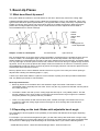
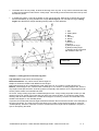
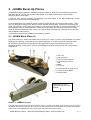
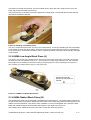
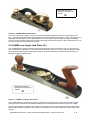
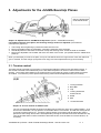
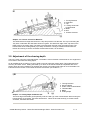
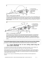
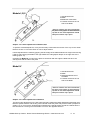
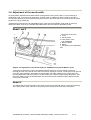
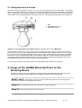
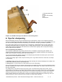
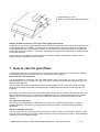
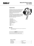
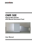
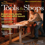
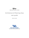
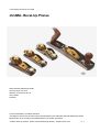
User Manual and Hints for Usage
JUUMA- Bevel-Up Planes
Dieter Schmid Werkzeuge GmbH
www.fine-tools.com.com
Wilhelm-von-Siemens-Str. 23
12277 Berlin
Germany
Text and Illustrations: Friedrich Kollenrott
The Rights of Use for this document (text and illustrations) are with Dieter Schmid Werkzeuge GmbH.
Reproduction by any means is prohibited without prior written permission.
JUUMA- Bevel-up Planes - Dieter Schmid Werkzeuge GmbH - www.fine-tools.com
P. 1
1. Bevel-Up Planes
1.1 What does Bevel-Up mean?
Every plane blade is beveled on one side and flat on the other. Where they meet is the cutting edge.
Traditional wooden planes usually have the blade set at 45 degree, bevel on the underside. This is also
typical with metal bench planes (left illustration.) The opposite side is usually covered by a separate chip
breaker (not shown here), which has a bevel which faces up to deflect the shavings. Most bevel-down
planes have a wedge-shaped frog that can be moved forward or back to adjust the mouth width to
accommodate thicker or thinner shavings.
1 Blade
2 Bevel
3 Mirror Side
4 Sole
5 Frog
6 Bed
7 Sliding plate for
mouth adjustment
Graphic 1: Parts of a metal plane
left: bevel-down
right: bevel-up
But, as the illustration on the right shows, placing the blade in a plane bevel up is possible as well. The iron
is set at a flatter, 12 to 20 degree angle, and the bevel acts as the chip breaker. This style requires a
shallow wedge to be integrated onto the body of the plane, between the bed and the sole. This design leads
to a very thin edge on the rear portion of the mouth, and thus wood is not strong nor ridged enough for bevel
up planes. This is why bevel-up planes are always made from metal such as cast-iron. In Germany, planes
were traditionally made from wood, so bevel-up planes were largely unknown until cast-iron planes from the
United States were imported to Europe.
Bevel-up planes are too narrow between bed and sole for a frog to fit. This is why the mouth opening is
adjusted with a sliding sole instead (graphic 1, right.)
A bevel-up or bevel-down blade in a plane is not an indicator of quality, but rather provides woodworkers
with very different performance characteristics.
Bevel-up characteristics:
Bevel-up planes are much flatter due to the shallower angle of the blade. That leads to a more
comfortable usage, especially with one hand. That is why the very popular one-handed cast-iron planes
are usually bevel-up.
The blade is fixed in the bed up to the cutting edge and thus kept in a very stable position. This will
prevent chattering even when working on hard wood as the bevel will not get caught in the material.
The plane performs very quietly under any conditions.
There is no chip breaker as with a bevel-down plane. Instead, the angle of the blade bevel can be
increased to make the cutting angle will be much larger for when working with wood that has a
tendency to tear.
1.2 Depending on the task: Blades with adjustable bevel-angle
One advantage of bevel-up planes is the possibility to use blades with different bevel angles depending
on the task.
For example: if you smooth wood against the grain, you will often end up with small holes or larger rough
dents. This damage occurs if the plane doesn’t cut the wood, but rather tears at the grains it and pulls them
out. But even in challenging wood this damage can be avoided don’t if you heed the following advice.
JUUMA Bevel-up Planes - Dieter Schmid Werkzeuge GmbH - www.fine-tools.com
P. 2
1.
The blade has to be very sharp, to allow the shaving to be very thin. A very narrow mouth will also help
to keep the wood down until it hits the cutting edge. This usually prevents tears with both bevel-up and
bevel-down planes.
2.
In challenging cases, it can help to deflect or even jolt the shaving. With bevel-up planes this can be
achieved beautifully by using a blade with a larger bevel-angle β. This will lead to a larger cutting
angle δ and therefore a steeper standing shaving which is more deflected.
1. Sole
2. Sliding plate
3. Bed
4. Shaving
5. Mouth
6. Blade
v. Direction of
movement
β. (Beta) Bevel-angle
δ. (Delta) Cutting-angle
ε. (Epsilon) Angle of the bed
with relation to the sole
Profile view
Graphic 2: Cutting process with bevel-up plane
Top Illustration: wide mouth, Bevel-angle 25°
Bottom Illustration: very narrow mouth, Bevel-angle 50°
Graphic 2 shows the relations with different bevel-angles.
Top: A Bevel-angle of 25° combined with a bed angle of the of 12° results in a cutting-angle of 37°.
Bottom: A bevel-angle of 50° combined with a bed angle of 12° results in a cutting angle of 62°, which is
very large but has practical uses. A bevel-up plane is especially well suited for such a high angle and can
ensure perfect results even with difficult wood.
Of course, a large cutting angle has it’s disadvantages as well. A large cutting angle also means you will
need more force to smooth your wood and your plane won’t work as easily. If you want to plane thicker
shavings with less effort a blade with a smaller bevel-angle is necessary. It is also recommended to use
smaller bevel-angles on one-handed planes.
In practice, this means that a bevel-angle somewhere between the two extremes shown in the examples is
the most convenient. The most common bevel-angle is 25° (which is also the bevel-angle on most new
JUUMA planes). However, instruction on how to increase the bevel angle will be explained in chapter 6 –
Tips for sharpening the blade.
JUUMA Bevel-up Planes - Dieter Schmid Werkzeuge GmbH - www.fine-tools.com
P. 3
2. JUUMA Bevel-Up Planes
JUUMA planes closely follow the standards of the top models of American tool manufacturers from the
first half of the 20th century, but are also improved with up to date manufacturing, modern quality
assurance and metric threads.
A cast-iron body ensures longevity and durability. The hefty weight of the plane guarantees smooth
working even over branches and irregularities.
Accurate adjustment of the blade is always necessary, and a natural part of working with a plane. This is
due to a good plane needing to be able to cut thick and thin shavings alike. Furthermore, sharpening the
blade may cause the cutting edge of the blade to no longer be perpendicular to the sides of the blade, and
this irregularity must be compensated for. JUUMA bevel-up planes have a knurled screw and a locking
wheel to make the adjustment easy. There is no need to adjust the blade with a hammer as it is the case
with traditional wooden planes.
JUUMA bevel-up planes are available in the following models:
2.1. JUUMA Block Plane (I)
This plane features a 35mm wide blade that is set at a 20° angle. It can be used universally for precise
shaping and smoothing of small pieces even without clamping. It can also be used for end-grain wood.
All important explanations and examples are also applicable to the other models Because of the
similarities between all the planes covered, the standard block plane will be used for the most pertinent
explanations.
1
2
4
5
Sole, rear
Sole, front part
Lever for mouth-opening
Front Knurled-screw for
sole
6 Blade
7 Lever Cap
8 Knurled-Screw for depth of cut
9 Locking wheel for Blade
10 Thumb indent
Explanations that are
specific for this plane are
marked:
I
Graphic 3: JUUMA Block Plane
The sole is the smooth bottom part of the cast-iron body. It consists of two parts. The front part up to the mouth is
adjustable. With the help of a lever the sole part can be moved forward and backwards to precisely set the width
of the mouth. Once adjusted, the sole can be locked into place with a knurled screw.
JUUMA Bevel-up Planes - Dieter Schmid Werkzeuge GmbH - www.fine-tools.com
P. 4
The blade is mounted onto the bed. The bed is milled into the body with a 20° angle from the sole. The
brass cap presses the blade onto the bed.
The knurled-screw on the back of the plane adjusts the cutting depth. The knurled-wheel underneath the
cap fastens the blade to the bed.
Picture 4: Handling of the Block plane.
The cap is contoured at the end to cup (fit?) your hand perfectly. Thumb and middle finger rest comfortably
in the indents on each side of the plane. The front screw can be gripped with two fingers or pressed down
by the thumb of the second hand for better control or greater pressure. The plane can be equally used right
or left handed.
2.2 JUUMA Low Angle Block Plane (II)
This plane is very similar to the standard block plane and is used for the same tasks. The blade is 35mm wide
as well but it is set at a shallower angle of 12°. This will keep the cutting angle shallower, even with a steeper
bevel angle for more stability and smoother working (compare graphic 2). This is advantageous if there is no
fear of tearing for example while working on end-grain wood.
Explanations that are
specific for this plane are
marked:
II
Picture 5: JUUMA Low Angle Block Plane
2.3 JUUMA Rabbet Block Plane (III)
This rabbet block plane has an blade that is shaped like an upside down T. The cutting edge is with 44mm
as wide as the plane body and the widest part of the blade. This is especially useful for finishing planning of
rabbets, tenons and dadoes. This plane is much shallower, of a more manageable size, and with a wider
blade than traditional high and narrow side rabbet planes. The angle of the bed is 12°.
The handling of the rabbet block plane is the same as with the other block planes.
JUUMA Bevel-up Planes - Dieter Schmid Werkzeuge GmbH - www.fine-tools.com
P. 5
.
Explanations that are
specific for this plane are
marked:
III
Picture 6: JUUMA Rabbet Block Plane
The body of the plane is open on the sides leaving the shallow angled bed and sole unsupported by the
body. That makes the rabbet block plane slightly less durable than the block planes I and II. The mouth is not
adjustable and the blade is not as rigidly fastened. Only if the planes special ability to smooth something
around a corner does the rabbet plane have an advantage over the block planes I and II. Nevertheless, it can
be used for general planning as when needed.
2.4 JUUMA Low Angle Jack Plane (IV)
This JUUMA bevel-up plane is similar to the block planes but is a full-size bench plane. It is 350 mm long
and comparable to a #5 Stanley. The blade is 50mm wide and set on a 12° angle. This bench plane can be
used for general planning and smoothing of larger work pieces. Because of its bevel-up construction, it is
especially useful for difficult wood.
Explanations that are
specific for this plane are
marked
IV
Picture 7: JUUMA Low Angle Jack Plane
The notable difference of the bench plane in comparison to the block planes is the combined Norris type
shaving-thickness adjustment and lateral adjustment. More details about this feature in the next chapter.
This jack plane features a sliding sole to adjust mouth width. It has a wooden handle and knob for pushing
and working with both hands as is usual with iron bench planes. The bench plane can be used right or left
handed.
JUUMA Bevel-up Planes - Dieter Schmid Werkzeuge GmbH - www.fine-tools.com
P. 6
3. Adjustments for the JUUMA Bevel-Up Planes
Only the angled area
of the bed is shown
Graphic 8: Adjustments for JUUMA Bevel-Up Planes (shown: JUUMA Block Plane I)
For faultless working of the plane, the following settings need to be adjusted: (The Numbers
correspond to graphic 8):
1.
2.
3.
4.
The locking wheel: tightening it presses the blade onto the bed.
Moving the blade forward or backwards: controls the thickness of the shavings.
Lateral adjustment of the blade on the bed: to keep the shavings even across the width of the blade.
Moving the adjustable sole forward and back: the width of the mouth. (not possible with the rabbet block
plane III)
When you first adjust your brand new plane, it may be a bit difficult due to the rough surface of the new milled and
ground material. This will change quickly after some usage, and future adjustments will go more smoothly.
3.1. Tension control
The blade needs to be able to move easily on the bed when adjusting shaving size and lateral position. It
also needs to be able to be seated firmly on the bed while the plane is in use so it does not move while
working. The locking wheel allows for the proper tension on the blade to prevent or allow blade movement
as needed. To ensure the perfect pressure the locking wheel should be adjusted slowly and carefully.
I,II,III
1
2
3
4
Turning Direction
Draw Bolt
Cap
Locking wheel with
knurled wheel
5 Blade
6 Bed
F Contact Pressure
Graphic 9: Tension Control for Models I,II.III
The cap (3) should fit beneath the head of the draw bolt (2) when the cap is at it’s tightest setting. As is
shown in the illustration, the cap presses on the blade with it’s front surface, and with the locking wheel,
to provide contact pressure (F.) Turning the locking wheel (4) increases and decreases the contact
pressure at the locking wheel, and is accomplished by turning the knurled brass wheel beneath the cap.
Turn the knurled wheel counter-clockwise to decrease tension, and clockwise to increase tension, as
necessary
JUUMA Bevel-up Planes - Dieter Schmid Werkzeuge GmbH - www.fine-tools.com
P. 7
IV
1
2
3
4
Turning Direction
Draw Bolt
Cap
Locking wheel with
knurled wheel
5 Blade
6 Bed
F Contact Pressure
Graphic 10: Tension Control for Model IV
The draw bolt has a ledge that serves as a stop and presses onto the bed. The cap is slid using the
“key hole” underneath the draw bolt’s head as a guide. The wide front edge of the cap rests on the
blade close to the cutting edge. The back is pressed down through using the locking wheel. The
knurled head of the locking wheel (4) is easily accessible. Turning it clockwise will increase the
tension and turning it counter-clockwise will decrease tension, as necessary.
3.2. Adjustment of the shaving depth
This is the most commonly used adjustment. The blade is moved forward or backwards on the angled bed
to increase or decrease the cutting depth.
On all JUUMA bevel-up planes a screw or shaft is used to adjust the cutting depth. This guarantees both
accuracy and ease of use. Sliding the blade up or down on the bed should be accompanied with some
friction. Minor and even resistance is required and normal, but needing great effort to move the blade is an
indication that the tension on the blade should be decreased. (see section 3.1.)
I,III
1.
2.
3.
4.
5.
6.
Turning Direction
Knurled Wheel
Collar of the Knurled Wheel
Threaded Bolt
Blade
Cutting depth
Graphic 11: Cutting Depth for Models I,III
The back edge of the blade (5) fits perfectly onto the collar (3) of the knurled wheel. When turning the
knurled wheel (2) clockwise, the blade will advance. When the knurled wheel (2) is turned counterclockwise, the blade will retreat.
JUUMA Bevel-up Planes - Dieter Schmid Werkzeuge GmbH - www.fine-tools.com
P. 8
II
1 Turning direction
2 Threaded spindle with
knurled head
3 Angle adjuster
4 Blade
5 Cutting depth
Graphic 12:Cutting Depth for Model II
Turning the knurled head (2) will turn the threaded spindle. This will also move the angle adjuster that
is connected with the spindle through a groove (slot). Lobes (pins) on the top of the angle adjuster
connect to slots on the bottom of the iron and move the blade in position. Turning the knurled head
(2) clockwise will advance the blade. Turning the knurled head (2) counter-clockwise will cause the
blade to retreat.
IV
1 Turning direction
2 Knurled head with
threaded spindle
3 Spindle retainer
4 Dog
5 Blade
6 Cutting-depth
Graphic 13: Cutting Depth for Model IV
This jack plane has a combined Norris-type cutting depth and lateral adjustment. The spindle has
two successive threads. The thicker one screws into the spindle retainer that is anchored into the
plane body. The thinner thread is screwed into the dog. The shaft is connected to the blade and
moves it along. Both threads are right handed but with a different pitch. To advance the blade, turn
the knurled head (2) clockwise. Turning the knurled head counter-clockwise will cause the blade to
retreat.
There should always be moderate tension on the blade (don’t over-crank it). To prevent inadvertent
movement of the blade always try to adjust from thinner to thicker. Even when the shaving needs to
get thinner it is better to adjust down past the desired thinness and then increase the width.
3.3. Lateral adjustment for an even cutting depth along the
entire width of the blade
This adjustment is always necessary when the blade is reinserted into the plane. As an example, this
adjustment would be done after placing the blade back into the plane after sharpening.
Lateral adjustment is done by pivoting the blade minimally at the leading edge, until the cutting depth is
even along the entire width of the blade. Sometimes, this adjustment is also necessary while working; to
correct an initial askew mounting of the blade or to counteract a divergence in the right angle between
cutting edge and side of the blade.
Because of the low angle of the blade bedding the precision needed for the lateral adjustment is
minimal.
JUUMA Bevel-up Planes - Dieter Schmid Werkzeuge GmbH - www.fine-tools.com
P. 9
Models I,II,III
1 Lateral Movement
2 Blade
3 Rotational of the blade
4 Forward movement of one
side of the blade
Note: For a better view of the mechanism,
the plane in the graphic is shown with the
cap left off. The actual adjustment should
take place with the cap in place
Graphic 14: Lateral adjustment on Models I,II,III
To perform a lateral adjustment, it may be necessary to decrease the tension of the cap on the blade.
Refer to section 3.1 for instructions on how to adjust tension.
Lateral adjustments are made by gripping the back edge of the blade between two fingers and moving
it side to side. Moving the blade to the right makes the cutting depth deeper on the right side or the
blade (graphic 14).
Important for Model III: In order for the plane to work flush with the edge the blade has to be set
exactly flush with the side of the plane
Model IV
1 Lateral Movement
2 Blade
3 Rotational Movement of
the blade
4 Forward movement of one
side of the blade
Note: For a better view of the mechanism,
the plane in the graphic is shown with the
cap left off. The actual adjustment should
take place with the cap in place!
Graphic 15: Lateral adjustment on Model IV
The Norris type adjustment on the low angle jack plane makes the lateral adjustment especially easy.
Both the spindle retainer and the dog can be turned inside the plane body and the blade (compare to
graphic 13). If you move the knurled head of sideways the spindle pivots around the retainer like the
two armed lever. The dog forces the blade to move in the opposite direction.
JUUMA Bevel-up Planes - Dieter Schmid Werkzeuge GmbH - www.fine-tools.com
P. 10
3.4. Adjustment of the mouth width.
An appropriately adjusted mouth width makes working with the plane even easier. For fine shavings on
challenging wood, a narrow mouth works best. A wider mouth is suitable for thicker shavings and when
smooth, easy planning is more important than pull prevention. Be aware that a too narrow mouth will cause
the plane to clog up frequently.
JUUMA bevel-up planes have an adjustable portion of the sole that regulates mouth width by moving it
forward and back. Only the one handed side rabbet plane does not have an adjustable mouth.
Model I and II
1.
Movement of the lever
2. Lever
3. Knurled knob
4. Front portion of the
sole, adjustable
5. Bevel of blade
6. Mouth
7. Movement of the adjustable
sole
Graphic 16: Adjustment of the mouth width on JUUMA bevel-up planes Model I and II
Turning the knurled knob counter-clockwise decreases tension on the front portion of the sole.
Pivoting the lever to the left will move the sole forward, opening the mouth. Pivoting the lever right will
move the sole backwards, decreasing the mouth width. For better visibility of the mouth and more
accurate adjustment, place the plane on a light surface like a sheet of paper during adjustment. After
the mouth width is set to the desired width, turn the knurled knob clockwise until the desired tension
on the sole is achieved.
Model IV
The adjustment of the bench plane is the same as with the one handed planes, except the loosening
of the front portion of the sole is done by turning of the wooden knob at the front of the plane.
JUUMA Bevel-up Planes - Dieter Schmid Werkzeuge GmbH - www.fine-tools.com
P. 11
4. Removal and replacement of the blade
It is often necessary to remove the blade from the plane for many reasons, such as sharpening the
blade. The following directions will describe the operations necessary to remove and replace the
blade.
4.1. Removing the blade
Before removing the blade, it is helpful to set the cutting depth to zero. Loosen the locking wheel and pull
the cap out from under the tension screw head. Remove the blade carefully.
Model III:
The wide front edge has to be carefully removed from the slots on the side of the plane
body.
Model IV:
Often the blade will get caught on the dog or the head of the tension screw. The easiest
way to remove the blade is as follows: Press the front edge of the blade onto the bed with your finger (the
cutting edge should be in the slot between bed and sole to prevent damaging it). Lift the back edge up until
it hits the screw head; this releases the blade from the dog. Now you can carefully pull the blade out the
back until the screw head passes through the key hole at the back of the blade.
4.2. Reinsertion
Reinsert the blade the same direction you took it out.
Attention: Insert the newly sharpen blade carefully as not to scratch the sides or the bed of the
plane.
Model II: The distance between the back edge of the blade and the knurled head of the spindle should
be about 5mm if the blade is new and full length. If the length of the blade decreases due to use and
sharpening a larger distance is useful.
Model III: Reinsert the blade carefully the same way as you took it out.
Model IV:
If the blade is new and full-length, the front cylindrical hole of the blade is pushed through
the screw top of the dog (see graphic 13.) The distance between the back edge of the blade and the
knurled head of the spindle should be about 5mm to 10 mm apart. For the positions of the dog and the
spindle retainer, see graphic 13. On a shorter blade, due to usage and sharpening, the second one of the
cylindrical holes should be pushed through the dog. That will also increase the distance between the blade
and the knurled head.
With the locking wheel turned all the way to the counter-clockwise, place the head of the tension
screw through the hole in the cap and retighten the locking wheel.
Adjust the blade and cap so that the cap is symmetrical on the blade, and the mouth width is even.
III: For planning rabbets, the corners of the
blade and the side panels of the body have to be flush. Due to
small discrepancies in manufacturing, the width of the blade and the width of the plane body can differ
slightly. That is why the side of the blade and the body that is used towards the rabbet should be the flush
ones. The plane is laid on its side on an even surface and the blade is pushed carefully down.
JUUMA Bevel-up Planes - Dieter Schmid Werkzeuge GmbH - www.fine-tools.com
S. 12
4.3. Readjustment of the blade
The blade should be adjusted so that it can cut a very thin shaving along its entire width. The shaving
should not be thicker than 1/10 mm to 2/10 mm; really thin shavings are only a few hundredth of a millimeter
thick. The thickness of the shavings determines how far the blade has to extend out of the mouth. Extremely
small widths may not measurable with conventional tools (i.e. rulers) but should be visible to the naked eye.
1 Sole
2 Adjustable sole plate
3 Protruding blade
Graphic 17: First adjustment of the blade “by eye” (example: bench plane Model IV)
First the blade is turned in as to not extend out the mouth over the sole. Hold the plane in front of a light
surface and look over the sole, holding the plane level so that the mouth opening cannot be seen as a dark
line. Now turn the knurled depth adjustment knob as to increase cutting depth (see section 3.2 for detailed
instructions on how to adjust cutting depth) until a dark line appears. This line should be thin and as even
as possible. Often the lateral adjustment has to be done to achieve a perfectly straight edge (see section
3.3 for detailed instructions on how to perform a lateral adjustment.)
For fine tuning the plane, start working with it and adjust depth and evenness as necessary.
5. Usage of the JUUMA Bevel-Up Plane on the
Shooting Board
Because the sides of the Juuma planes are perfectly flat and perpendicular to the sole they can be
used for a 90 degree chamfer (especially for cross-grain wood) on the shooting board.
Model I and II: These planes can only be used for small working pieces on the shooting board
due to their low weight and small width of the blade.
Model III: The rabbet block plane cannot be used on the shooting board.
Model IV: The perfect plane for the shooting board.
JUUMA Bevel-up Planes - Dieter Schmid Werkzeuge GmbH - www.fine-tools.com
P. 13
1 Shooting board with
groove
2 Stop of the shooting
board
3 Work piece
Graphic 18: JUUMA Low Angle Jack Plane on the shooting board
6. Tips for sharpening
Most woodworking tools are only pre-sharpened by the manufacturer, and are not at optimal sharpness.
However, JUUMA high quality planes are already well sharpened, and ready to go to work straight out of the
box. But the work quality will increase drastically if you continue to sharpen your blade to perfection.
Every plane will get dull from use and has to be re-sharpened. JUUMA planes are very high quality and
keep their sharp blade edge for a long time, but no cutting edge lasts forever. That’s why working with a
plane always requires sharpening from time to time. It is best done regularly and not only when working
with the plane becomes difficult.
How to sharpening plane blades?
Very important: High-speed, dry grinding machines are not suitable for sharpening plane blades. The
wheels on these machines are too coarse and not precise enough. Grinding machines can overheat the
blade easily, ruining the annealing which will soften the steel.
You may use special wet grinding machines, but sharpening by hand with wet stones gives you the same
quality and can be done quickly and easily.
A really good cutting edge is razor sharp and exactly even. To get these results in a short time, two steps
are necessary:
1. Grinding (of the bevel) is done first to remove the old dull edge and eventual damages to the blade. This
is done with a relatively coarse, fast working stone.
2. Honing (with a very fine stone) for a high quality of the new cutting edge.
Bevel and reverse side can be honed the entire length of the blade but this is very time consuming if done
by hand. Instead micro bevels can be honed directly at the cutting edge. The result is the same and it can
be done much faster.
All JUUMA planes come with the bevel set (ground?) at 25°. An blade with this angle will cut easily, but the
cutting edge is very delicate. It is generally recommended to have a bevel angle of at least 30° if a longer lasting
edge is required. This will make the cutting edge more robust without requiring too much more effort. Especially
with bevel-up planes, the bevel angle may be set at an even steeper angle (as seen in Graphic 2) to achieve
better longevity without much risk of pulling. It is easy to increase the bevel angle during sharpening. Even just
setting a small micro bevel during honing can increase the cutting angle sufficiently.
JUUMA Bevel-up Planes - Dieter Schmid Werkzeuge GmbH - www.fine-tools.com
P. 14
1 Original Bevel ( β = 25°)
2 New micro-bevel with larger cutting angle
β
Graphic 19: Blade honed to a new, larger cutting angle (micro bevel)
On graphic 19, the blade’s original 25 degree bevel has been replaced by a thin, steeper bevel grinded onto
it at the leading edge of the blade. A small bevel such as this doesn’t cause any problems, but rather has
the advantage that only a small amount of steel has to be taken off to maintain the bevel, thus making the
sharpening process much faster. Conversely, sharpening the entire bevel of the blade to a shallower angle
is very work-intensive.
Instructions on how to sharpen a blade cannot be described in detail in this manual. However, there is
plenty of literature available, in print and online.
7. How to care for your Plane
JUUMA planes are fine wood working tools. To enjoy them for a long time and to ensure proper workings
it is important to treat them carefully and clean and maintain them regularly.
Rust Prevention and Lubrication
It is recommended to protect the sole, the blade and the side of the plane if it is not in used for an
extended period of time or stored in a damp environment. A drop of oil is sufficient. The plane body can
also be treated with wax.
The back side of the blade is especially sensitive and susceptible for rust. To prevent rusting the blade
needs to be thoroughly dried after wet sharpening and rubbed down with oil before inserting it back into
the plane.
Some parts of the plane need to be oiled occasionally to ensure smooth working and to prevent wear. The
threat on the knurled screw (I, III), threat of the spindle and dog (II) the threat of the dog and the spindle
retainer (IV), the screw and the tracks in the movable part of the sole and the bed need to be oiled
regularly.
The right size screw driver
The screws in all JUUMA planes traditionally have screws with a flat head, and are soft. To prevent
unsightly damage to the screws, a properly fitting flat head screwdriver is recommended for making
adjustment.
Repair of damages to the sole
The sole of the plane will not stay perfectly smooth and shiny forever, but this is not a problem. However, larger
and more severe damage such as gouges, deep scratches and rust can damage work pieces. Severe damage
requires the sole to be lapped smooth.
JUUMA Bevel-up Planes - Dieter Schmid Werkzeuge GmbH - www.fine-tools.com
P. 15
It is important that the flatness of the sole is preserved. To assure that a large flat surface with abrasive
properties is necessary. This can be done with wet-dry sanding paper that is taped onto a perfectly flat
surface (i.e. thick plate glass, granite window sill etc.) Make sure to remove all unevenness from the sanding
paper, like price tags etc.
Ensure that the movable front portion of the sole stays in place and is well tightened. The blade stays in the
plane but is pulled back to no cutting depth. That will ensure that the plane is in the same shape as it is
when used, as the tightened blade warps the plane ever so slightly.
Now the plane is pulled over the wet sanding paper. If necessary a very coarse paper with a grid of 80 can
be used at first. The last paper should be very fine, at least a grid of 240. After the lapping, the blade should
be removed and it, and the entire plane, has to be dried and oiled properly to prevent rusting.
JUUMA Bevel-up Planes - Dieter Schmid Werkzeuge GmbH - www.fine-tools.com
P. 16