1
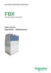
Secondary Distribution Switchgear
FBX
SF6 Gas-insulated switchboards
Instructions
Guide for Civil Engineering
Structures
FBX
Contents
1
Schneider Electric at your service . . . . . . . . . . . . . . . . . . .
1
1.1
1.2
Our Service Unit: our specialists, and suitably adapted services... . . . . . . . . .
Schneider Electric Training: Together, let us develop our skills... . . . . . . . . . . .
1
1
2
With regards to this User Manual . . . . . . . . . . . . . . . . . . . .
2
2.1
2.2
2.3
2.4
2.5
Use of this User Manual . . . . . . . . . . . . . . . . . . . . . . . . . . . . . . . . . . . . . . . . . . . .
Responsibilities . . . . . . . . . . . . . . . . . . . . . . . . . . . . . . . . . . . . . . . . . . . . . . . . . . .
Definition of the substations . . . . . . . . . . . . . . . . . . . . . . . . . . . . . . . . . . . . . . . . .
Access to the substation . . . . . . . . . . . . . . . . . . . . . . . . . . . . . . . . . . . . . . . . . . . .
Other technical notices to be consulted . . . . . . . . . . . . . . . . . . . . . . . . . . . . . . . .
2
2
2
2
2
3
Dimensions of the FBX switchboards . . . . . . . . . . . . . . . .
3
3.1
3.2
3.3
3.4
3.5
3.6
Description of the functions . . . . . . . . . . . . . . . . . . . . . . . . . . . . . . . . . . . . . . . . .
Overall dimensions . . . . . . . . . . . . . . . . . . . . . . . . . . . . . . . . . . . . . . . . . . . . . . . .
Ground plan dimensions . . . . . . . . . . . . . . . . . . . . . . . . . . . . . . . . . . . . . . . . . . . .
Dimensions and weights of the FBX-C switchboards (non-extendable model)
Dimensions and weights of the FBX-M switchboards . . . . . . . . . . . . . . . . . . . .
Dimensions and weights of the FBX-E switchboards (extendable model) . . . .
Extendable switchboards . . . . . . . . . . . . . . . . . . . . . . . . . . . . . . . . . . . . . . . . . . .
Functional Unit - Extension . . . . . . . . . . . . . . . . . . . . . . . . . . . . . . . . . . . . . . . . . .
3
3
3
4
4
5
5
5
4
General rules for the installation of FBX switchboards
6
4.1
Reminder concerning normal installation and service conditions
(in accordance with IEC62271-1) . . . . . . . . . . . . . . . . . . . . . . . . . . . . . . . . . . . . .
* Permissible ambient temperature . . . . . . . . . . . . . . . . . . . . . . . . . . . . . . . . . . .
* Installation altitude . . . . . . . . . . . . . . . . . . . . . . . . . . . . . . . . . . . . . . . . . . . . . . . .
* Atmospheric pollution . . . . . . . . . . . . . . . . . . . . . . . . . . . . . . . . . . . . . . . . . . . . .
* Permissible atmospheric humidity level . . . . . . . . . . . . . . . . . . . . . . . . . . . . . .
Substation installation requirements . . . . . . . . . . . . . . . . . . . . . . . . . . . . . . . . . .
Installation of the switchboard . . . . . . . . . . . . . . . . . . . . . . . . . . . . . . . . . . . . . . .
Examples of the positioning of an FBX switchboard in a room . . . . . . . . . . . . .
6
6
6
6
6
6
6
7
5
Installation of an FBX-C switchboard . . . . . . . . . . . . . . . .
8
5.1
Switchboard up to 20 kA (AF - 1 s) - Rearward evacuation Standard Installation . . . . . . . . . . . . . . . . . . . . . . . . . . . . . . . . . . . . . . . . . . . . . . .
Switchboard up to 20 kA (AF - 1 s), with gas exhaust cooler towards the rear
16, 20 and 25 kA Switchboards (AF/AFL - 1 s), with solid rear panel and gas
exhaust towards the bottom . . . . . . . . . . . . . . . . . . . . . . . . . . . . . . . . . . . . . . . . .
16 and 20 kA Switchboards (AFL - 1 s), with gas exhaust towards the rear . .
16 and 20 kA switchboards (AFL - 1S) with rear-mounted chimney . . . . . . . .
9
9
10
6
Installation of an FBX-E switchboard . . . . . . . . . . . . . . . .
11
6.1
Switchboard up to 20 kA (AF – 1 s) [except if M or CBb function] - Rearward
evacuation - Standard Installation . . . . . . . . . . . . . . . . . . . . . . . . . . . . . . . . . . . .
Switchboard up to 20 kA (AF - 1 s), with gas exhaust cooler towards the rear
16, 20 and 25 kA Switchboards (AF/AFL - 1 s), with solid rear panel and gas
exhaust towards the bottom . . . . . . . . . . . . . . . . . . . . . . . . . . . . . . . . . . . . . . . . .
16 and 20 kA Switchboards (AFL - 1 s), with gas exhaust towards the rear . .
12
12
7
Installation of an FBX-E switchboard with M or CBb
Function . . . . . . . . . . . . . . . . . . . . . . . . . . . . . . . . . . . . . . . . . . .
13
7.1
7.2
7.3
16 kA and 20 kA Switchboards (AF - 1 s), with gas exhaust towards the rear
16 and 20 kA Switchboards (AFL - 1 s), with gas exhaust towards the rear . .
16 kA and 20 kA Switchboards (AF/AFL - 1 s), with gas exhaust towards the
bottom . . . . . . . . . . . . . . . . . . . . . . . . . . . . . . . . . . . . . . . . . . . . . . . . . . . . . . . . . . .
13
14
8
Installation of an FBX switchboard C or E . . . . . . . . . . . .
16
8.1
8.2
8.3
8.4
8.5
8.6
Dimensions for switchboards . . . . . . . . . . . . . . . . . . . . . . . . . . . . . . . . . . . . . . . .
Geometry of the switchboard and civil engineering structure . . . . . . . . . . . . . .
Installation on the floor (refer to table § 8.1) . . . . . . . . . . . . . . . . . . . . . . . . . . . .
Layout and fixing of the FBX-C or E to the floor . . . . . . . . . . . . . . . . . . . . . . . . .
Positioning of fixing points . . . . . . . . . . . . . . . . . . . . . . . . . . . . . . . . . . . . . . . . . . .
Fixing to the floor . . . . . . . . . . . . . . . . . . . . . . . . . . . . . . . . . . . . . . . . . . . . . . . . . .
16
16
17
18
18
18
4.2
4.3
4.4
5.2
5.3
5.4
5.5
6.2
6.3
6.4
AMTNoT110-02 revision: 10
8
8
11
11
15
i
FBX
9
Installation of an extension function . . . . . . . . . . . . . . . . .
19
9.1
9.2
Dimensions for extensions . . . . . . . . . . . . . . . . . . . . . . . . . . . . . . . . . . . . . . . . . .
Geometry of the switchboard and civil engineering structure
(see Tables § 8.1 & 9.1) . . . . . . . . . . . . . . . . . . . . . . . . . . . . . . . . . . . . . . . . . . . .
Installation on the floor (see Tables § 8.1 & 9.1) . . . . . . . . . . . . . . . . . . . . . . . . .
Layout and fixing of the FBX-E to the floor . . . . . . . . . . . . . . . . . . . . . . . . . . . . .
Positioning of an extension and of its fixing points . . . . . . . . . . . . . . . . . . . . . . .
Fixing to the floor . . . . . . . . . . . . . . . . . . . . . . . . . . . . . . . . . . . . . . . . . . . . . . . . . .
19
19
20
20
21
21
10
Work on the Civil Engineering structure . . . . . . . . . . . . . .
22
10.1
10.2
10.3
10.4
Characteristics of the work on the Civil Engineering structure . . . . . . . . . . . . .
Characteristics of the installation room . . . . . . . . . . . . . . . . . . . . . . . . . . . . . . . .
Characteristics of the storage area . . . . . . . . . . . . . . . . . . . . . . . . . . . . . . . . . . .
Geometry of the cable trough . . . . . . . . . . . . . . . . . . . . . . . . . . . . . . . . . . . . . . . .
22
22
22
23
11
LV & HV connections for an FBX switchboard . . . . . . . .
24
11.1
11.2
11.3
11.4
Distances between phases at HV connections level . . . . . . . . . . . . . . . . . . . . .
Altitudes for the LV & HV connection points . . . . . . . . . . . . . . . . . . . . . . . . . . . .
Connection of the switchboard earthing circuit . . . . . . . . . . . . . . . . . . . . . . . . . .
Disposition of connection point in M functions . . . . . . . . . . . . . . . . . . . . . . . . . .
24
25
25
26
12
Notes . . . . . . . . . . . . . . . . . . . . . . . . . . . . . . . . . . . . . . . . . . . . . .
27
9.3
9.4
9.5
9.6
ii
AMTNoT110-02 revision: 10
FBX
1 Schneider Electric at your
service
Operations and maintenance may only be
carried out by personnel who have received
suitable authorization for the operations and
manœuvres they are responsible for
performing.
If this is not the case, please refer to our
Service Unit or Training Centre.
1.1
All locking-out operations must be performed
according to the ”General Safety Instructions
booklet for Electrical Applications”
UTE C 18 510 (or its equivalent outside
FRANCE).
Our Service Unit: our specialists, and suitably adapted services...
Guarantee extension contracts in relation to
the selling of new equipment,
Supervision of HVA switchgear installations,
Technical advice, diagnoses of the facilities,
expertise,
Maintenance contracts adapted to operational
constraints,
Systematic or conditional preventive
maintenance,
Corrective maintenance in case of partial or
complete failure,
Supply of spare parts,
Overhauling of equipment and requalification
of installations in order to benefit from new
technologies and extend the life of your
switchgear by limited investments.
J
J
J
J
J
J
J
J
Contact the Schneider Electric Service Unit for diagnoses and advice:
Working hours
)
33 (0)3 85 29 35 00
33 (0)3 85 29 36 30
or
33 (0)3 85 29 36 43
1.2
Schneider Electric Training: Together, let us develop our skills...
We can place at your disposal all of our
trainers' expertise, our teams'
pedagogical experience and the wealth
of our equipment, to help you face the
challenge of encouraging the personal
development of each individual through
the optimization of their skills.
From a few hours up to several weeks,
Schneider Electric Training has the
control over all of the teaching
processes in order to meet the needs of
each customer.
J
J
J
J
Specific training, directly operational
with practical work on real machines.
Small groups to facilitate
communication.
Balance between theory and practice.
Evaluation and management of the
skills: Measurement and optimization of
the trainees' knowledge.
Faced with the direct and indirect training
costs of the operational stoppages and
shutdown, training is a real investment
Schneider Electric France
Training Centre
35 rue Joseph Monier - CS 30323 - F-92506 Rueil-Malmaison Cedex
www.schneider-electric.fr/formation
AMTNoT110-02 revision: 10
1
FBX
2 With regards to this User Manual
© - Schneider Electric - 2011. Schneider
Electric, the Schneider Electric logo and their
figurative forms are Schneider Electric
registered trademarks.
2.1
The other brand names mentioned within this
document, whether they be copyright or not,
belong to their respective holders.
Use of this User Manual
This User Manual describes the works or
arrangements necessary for the installation of
a HVA switchboard of the FBX type.
2.2
Responsibilities
Our devices are quality controlled and tested
at the factory in accordance with the
standards and the regulations currently in
force.
Apparatus efficiency and apparatus life
depend on the compliance with the
installation, commissioning and operation
instructions described in this user manual.
2.3
J
J
J
J
2
The indoor substations with “prefabricated
metal-clad bays” are installed in areas that
the User reserves in one of the buildings in
the factory, or in a building specially built for
this purpose for the case of transformer
substations for HVA distribution networks.
The recommended minimum volume for the
room is: 12 m3
Access to the substation
Substation access must remain free at all
times and under any circumstances. It is
therefore generally installed on the side of the
road.
2.5
Local requirements especially about safety
and which are in accordance with the
indications given in this document, must be
observed.
Definition of the substations
Amongst substations that are prefabricated or
built outdoors, walk-in substations can reach,
or even exceed 2.5 m in height. They allow
operating personnel to penetrate into the
substation and work in them sheltered from
bad weather.
2.4
Non respect of these instructions is likely to
invalidate any guarantee.
The texts in this User Manual refer to
international regulations.
Passages must be designed to permit easy
maintenance for all of the substation's
elements (circuit breaker, transformer, etc.).
Other technical notices to be consulted
AMTNoT131-02
AMTNoT132-02
AMTNoT170-02
AMTNoT174-02
FBX
Installation - Commissioning
FBX
Operation - Maintenance
FBX Function CB
Installation - Commissioning - Operation - Maintenance
FBX
Assembly a 1250A busbar
AMTNoT110-02 revision: 10
FBX
3.1
C
T1
T2
CB
CBb
R
RE
3.2
3 Dimensions of the FBX
switchboards
Description of the functions
= Load break switch
= Combined or associated fused interrupter switch
= Transformer protection circuit breaker
= Cables protection circuit breaker
= Busbar protection circuit breaker
= Direct linkage
= Direct incoming feeder with earthing switch
M1
M2
M3
M4
Sb
= Measurement with cable connections
= Measurement with RHS extension
= Measurement for LHS extension
= Measurement for extension (right or left)
= Busbar isolator
Overall dimensions
These are used to position the switchboard
within the room.
The dimensions for the total switchboard volume
(excluding optional extras) are:
- Width
- Depth
- Height.
Example for the depth of a switchboard
H
C
B
A: Operating passage
P: Overall depth
B: Distance to rear wall
C: Space for possible on-site
optional fitting
A
L
P
B
P
3.3
Ground plan dimensions
These are used for the civil engineering work
relating to the switchboard.
Example for the depth of a switchboard
In this case, the dimensions of the surfaces
touching the ground are given.
The reference face is the front panel as it
touches the ground. The sizes are taken from
this reference.
P: Depth
B: Distance to rear wall
Reference
face
AMTNoT110-02 revision: 10
P
B
3
FBX
3.4
Dimensions and weights of the FBX-C switchboards (non-extendable model)
Switchboard
Number of
modules
Height1)
Overall Depth (mm)
Depth2)
Width
Floor dimensions (mm)
Depth
Width
Weights
approximate (kg)
C-C
2
1380/1040
752
680
691
680
200
RE-T1
2
1380/1040
752
680
691
680
210
RE-T2
2
1380
752
680
691
680
240
C-T1
2
1380/1040
752
680
691
680
200
C-T2
2
1380
752
680
691
680
230
C-C-T1
3
1380/1040
752
1000
691
1000
330
C-C-T2
3
1380
752
1000
691
1000
360
C-C-C
3
1380/1040
752
1000
691
1000
320
C-RE-T1
3
1380/1040
752
1000
691
1000
320
C-RE-T2
3
1380
752
1000
691
1000
360
R-RE-T1
3
1380/1040
752
1000
691
1000
320
R-RE-T2
3
1380
752
1000
691
1000
350
C-C-C-T1
4
1380/1040
752
1320
691
1320
450
C-C-C-T2
4
1380
752
1320
691
1320
480
C-T1-C-T1
4
1380/1040
752
1320
691
1320
470
C-T2-C-T2
4
1380
752
1320
691
1320
500
C-C-C-C
4
1380/1040
752
1320
691
1320
440
C-C-C-C-C
5
1380
752
1675
691
1675
540
C-C-C-C-T1
5
1380
752
1675
691
1675
550
C-C-T1-C-T1
5
1380
752
1675
691
1675
580
C-T1-C-T1-T1
5
1380
752
1805
691
1805
570
1) Add 200 or 600 mm depending on the height of the box
2) Without a cooler at the rear. In the case of a cooler, add 38.5 mm
3.5
Dimensions and weights of the FBX-M switchboards
Module
Number of
modules
Overall Depth (mm)
Floor dimensions (mm)
Height
Depth1)
Width2)
Depth
Width
Weights
approximate (kg)
M1
1
1380
720
1000
691
1000
490
M2
1
1380
720
1005
691
1000
490
M3
1
1380
720
1005
691
1000
490
M4
1
1380
720
1010
691
1000
490
1) Without a cooler at the rear. In the case of a cooler, add 38.5 mm
2) Plus 17.5 mm for the busbar cover (on the right or left-hand side) at the far end of the switchboard
4
AMTNoT110-02 revision: 10
FBX
3.6
Dimensions and weights of the FBX-E switchboards (extendable model)
Extendable switchboards
Module
Number of
modules
Overall Depth (mm)
Floor dimensions (mm)
Height1)
Depth2)
Width3)
Weights
approximate (kg)
Depth
Width
C-C
2
1380
752
690
691
690
210
C-T1
2
1380
752
690
691
690
210
C-T2
2
1380
752
690
691
690
240
RE-T1
2
1380
752
690
691
690
220
RE-T2
2
1380
752
690
691
690
250
C-C-T1
3
1380
752
1010
691
1010
340
C-C-T2
3
1380
752
1010
691
1010
370
C-C-C
3
1380
752
1010
691
1010
330
C-RE-T1
3
1380
752
1010
691
1010
330
C-RE-T2
3
1380
752
1010
691
1010
360
R-RE-T1
3
1380
752
1010
691
1010
330
R-RE-T2
3
1380
752
1010
691
1010
360
C-C-C-T1
4
1380
752
1330
691
1330
460
C-C-C-T2
4
1380
752
1330
691
1330
490
C-T1-C-T1
4
1380
752
1330
691
1330
480
C-T2-C-T2
4
1380
752
1330
691
1330
510
C-C-C-C
4
1380
752
1330
691
1330
450
1) - Add 200 or 600 mm depending on the height of the box
2) - Without a cooler at the rear. In the case of a cooler, add 38.5 mm
3) - Plus 17.5 mm for the busbar cover (on the right or left-hand side) at the far end of the switchboard
- To calculate the total width of several connected FBX-E switchboards, add 9 mm between each extension
Functional Unit - Extension
Module
Number of
modules
Overall Depth (mm)
Floor dimensions (mm)
Height1)
Depth2)
Width3)
Weights
approximate (kg)
Depth
Width
C
1
1380
752
370
691
360
135
R
1
1380
752
370
691
360
125
RE
1
1380
752
370
691
360
135
T1
1
1380
752
500
691
490
160
T2
1
1380
752
500
691
490
190
CB
1
1380
873
500
691
490
220
CBb
1
1380
873
635
691
625
250
Sb
1
1380
752
690
691
680
200
T1-T1
2
1380
752
1010
691
1000
310
T2-T2
2
1380
752
1010
691
1000
370
1) - Add 200 or 600 mm depending on the height of the box
- With a 1250 A busbar on the top, add 217 mm
2) - Without a cooler at the rear. In the case of a cooler, add 38.5 mm
3) - Plus 17.5 mm for the busbar cover (on the right or left-hand side) at the far end of the switchboard
- To calculate the total width of several connected FBX-E switchboards, add 9 mm between each extension
AMTNoT110-02 revision: 10
5
FBX
4.1
4 General rules for the installation
of FBX switchboards
Reminder concerning normal installation and service conditions (in accordance
with IEC62271-1)
* Permissible ambient temperature
The ambient air temperature should be
comprised between - 5°C (on option -15
or -25°C) and + 40°C.
The mean measured value for a
24 hour period must not exceed 35°C.
* Installation altitude
HV equipment is defined in accordance with
European Standards and can be used up to
an altitude of 1,000 m.
Beyond this, account must be taken of the
decrease in dielectric withstand.
For these specific cases, contact the
Schneider Electric Sales Department.
* Atmospheric pollution
The ambient air must not contain any dust
particles, fumes or smoke, corrosive or
flammable gases, vapours or salts.
* Permissible atmospheric humidity level
The average atmospheric relative humidity
level measured over a 24-hour period must
not exceed 95%.
The average water vapour pressure over a
period of 24 hours must not exceed 22 mbar.
The average atmospheric relative humidity
value measured over a period of one month
must not exceed 90 %.
The average water vapour pressure over a
period of one month must not exceed
18 mbar.
4.2
Also prevent any penetration by small
animals such as rodents, snakes, lizards, etc.
especially in tropical areas.
The room must be equipped with
standardised high level and low level
ventilation.
Cable troughs and ducts must be blocked up
to avoid:
- any draughts of air below the Functional
Units,
- any rise in humidity or pollution coming from
below ground.
Installation of the switchboard
The positioning of the switchboard is
paramount for:
- minimum spaces at the front (walk-in
corridor for manoeuvering), at the rear and on
each side of the switchboard. Certain
passages must be sufficient for free
movement and execution of operation and
maintenance manoeuvres,
- leave the room's access door free,
- Take all measures to prevent all incidence of
climatic conditions (humidity, pollution, etc.).
6
Whenever the humidity level is higher than
90 %, we recommend that you take
appropriate corrective measures. For any
assistance or advice, contact the Schneider
Electric After-Sales department (See § 1.1).
Please consult Schneider Electric for
any installation conditions which differ
from the standard.
Substation installation requirements
The substation must be sheltered from
flooding and any infiltrations of water. No
ducts of any kind must pass through the
substation's immediate environment without
special protection (sheaths or ducts). Water,
snow, or animal salts must not be able to
penetrate.
4.3
Condensation may appear in case of any
sharp variation in temperature, due to
excessive ventilation, a high atmospheric
humidity level or the presence of hot air. This
condensation can be avoided by an
appropriate lay-out of the room or of the
building (suitably adapted ventilation, air
driers, heating etc.).
Respect the imposed distances (see
following chapter).
Do not place the switchboard below any
ventilation grilles, air vents, or air conditioning
grilles or in the immediate proximity of glass
tile panels in direct contact with the outside.
The switchboard must not be exposed to any
solar radiation. A direct exposure can lead to
excessive overheating of the low voltage
racks.
AMTNoT110-02 revision: 10
FBX
4.4
Examples of the positioning of an FBX switchboard in a room
Side views
Low-voltage cabinet
(optional)
1) Free passages for installation:
Busbar 1,250 A
ÄÄÄÄÄÄÄÄ
ÄÄÄÄÄÄÄÄ
ÄÄÄÄÄÄÄÄ
ÄÄÄÄÄÄÄÄ
ÄÄÄÄÄÄÄÄ
ÄÄÄÄÄÄÄÄ
ÄÄÄÄÄÄÄÄ
ÄÄÄÄÄÄÄÄ
ÄÄÄÄÄÄÄÄ
ÄÄÄÄÄÄÄÄ
ÄÄÄÄÄÄÄÄ
ÄÄÄÄÄÄÄÄ
ÄÄÄÄÄÄÄÄ
ÄÄÄÄÄÄÄÄ
ÄÄÄÄÄÄÄÄ
ÄÄÄÄÄÄÄÄ
1380
1578
Clearance
under ceiling
Minimum width: 950 mm
Mimimum height: 1,800 mm
2) Walk-in corridor:
FBX-C: > 800 mm for operations
FBX-E: > 950 mm to facilitate the
installation of extensible
switchboards
3) Clearance under ceiling:
Without LV cabinet: > 2,000 mm
With LV cabinet (200 mm): > 2,000 mm
With LV cabinet (600 mm): > 2,100 mm
With 1,250A busbar: > 2,100 mm
Walk-in corridor
752*
* + 38,5 mm with cooler
100
100
20
With rear deflector
AMTNoT110-02 revision: 10
Without rear deflector
With rear cooler
7
FBX
5.1
5 Installation of an FBX-C
switchboard
Switchboard up to 20 kA (AF - 1 s) - Rearward evacuation - Standard Installation
N.B.: recommended configuration in compliance
with type tests for the EDF HN64-S-52
specification.
100 (1)
Top view (dimensions in mm)
Rear arc deflector
> 2000
ÅÅÅÅÅÅÅÅÅÅÅ
ÅÅÅÅÅÅÅÅÅÅÅ
FBX-C
> 450
20 (1)
(1) Either flush with the lateral
or rear deflector, or > 450 mm
5.2
> 800
Walk-in
corridor
100
Switchboard up to 20 kA (AF - 1 s), with gas exhaust cooler towards the rear
> 140
Top view
(dimensions in mm)
752
FBX-C
> 2000
ÎÎÎÎÎÎÎÎÎ
Walk-in
corridor
> 800
> 100
8
140
AMTNoT110-02 revision: 10
FBX
5.3
16, 20 and 25 kA Switchboards (AF/AFL - 1 s), with solid rear panel and gas
exhaust towards the bottom
NB: This configuration is available for a
FBX of height 1040 or 1380 mm.
>100 mm
> 20
Top view
(dimensions in mm)
With or
without wall
FBX-C
Solid rear panel
> 20
> 20
Gas cooler
(not supplied)
Volume > 0.8 m3 (16 or 20 kA)
Cross-section of duct > 0.3 m2 (16 or 20 kA)
(with 5 layers of expanded metal, e.g. 6 x 3.4 x 0.5)
5.4
16 and 20 kA Switchboards (AFL - 1 s), with gas exhaust towards the rear
Top view (dimensions in mm)
D (1)
100
Blanking off
side panel
FBX-C
> 100 (2)
> 2000
752
ÎÎÎÎÎÎÎÎÎ
30
Walk-in
corridor
> 800
Blanking off
side panel
140
Blanking off
side panel
(1) D = 140
If D > 140, provide for additional blocking off (not supplied).
(2) If there is no left-hand wall, mount another side panel.
AMTNoT110-02 revision: 10
9
FBX
5.5
16 and 20 kA switchboards (AFL - 1S) with rear-mounted chimney
> 600
> 100
Top view
(dimensions in mm)
1780
FBX-C
> 20
> 20
870
10
> 100
AMTNoT110-02 revision: 10
FBX
6.1
6 Installation of an FBX-E
switchboard
Switchboard up to 20 kA (AF – 1 s) [except if M or CBb function] - Rearward
evacuation - Standard Installation
100 (1)
Top view
(dimensions in mm)
Rear arc deflectors
> 2000
ÅÅÅÅÅÅÅÅÅÅÅ
ÅÅÅÅ
ÅÅÅÅÅÅÅÅÅÅÅ
ÅÅÅÅ
752
FBX-E
20 (1)
100
Walk-in
corridor
> 950
> 450
(1) Either flush with the lateral
or rear deflector, or > 450mm
6.2
Switchboard up to 20 kA (AF - 1 s), with gas exhaust cooler towards the rear
140
Top view
(dimensions in mm)
> 2000
ÎÎÎÎÎÎÎÎÎ
ÎÎÎ
ÎÎÎÎÎÎÎÎÎÎÎÎ
752
FBX-E
> 450
AMTNoT110-02 revision: 10
Walk-in
corridor
> 950
> 100
140
11
FBX
6.3
16, 20 and 25 kA Switchboards (AF/AFL - 1 s), with solid rear panel and gas
exhaust towards the bottom
Top view
(dimensions in mm)
> 20
>100 mm
With or
without wall
FBX-E
Solid rear
panel
> 20
> 450
Gas cooler (not
supplied)
Volume > 0.8 m3 (16 or 20 kA)
Cross-section of duct > 0.3 m2 (16 or 20 kA)
(with 5 layers of expanded metal, e.g. 6 x 3.4 x 0.5)
6.4
16 and 20 kA Switchboards (AFL - 1 s), with gas exhaust towards the rear
Top view
(dimensions in mm)
100
752
ÎÎÎÎÎÎÎÎÎÎÎÎ
FBX-E
> 2000
D (1)
Blanking off
side panel
Blanking off
side panel
Walk-in
corridor
> 950
30
> 100 (2)
140
Blanking off
side panel
(1) D = 140
If D > 140, provide for additional blanking off (not supplied).
(2) If there is no left-hand wall, mount another side panel.
12
AMTNoT110-02 revision: 10
FBX
7.1
7 Installation of an FBX-E
switchboard with M or CBb
Function
16 kA and 20 kA Switchboards (AF - 1 s), with gas exhaust towards the rear
> 140
Top view
(dimensions in mm)
ÎÎÎÎÎÎÎÎÎÎÎÎÎÎÎÎÎÎ
M Function
CBb Function
752
FBX-E
Systems for limiting side or rear
access are the customer's
responsibility.
Walk-in corridor
> 950
> 100
Side view
(dimensions in mm)
Gas cooler (not
supplied)
> 2400
> 2000
AMTNoT110-02 revision: 10
Gas cooler (not
supplied)
100
100
140
140
13
FBX
16 and 20 kA Switchboards (AFL - 1 s), with gas exhaust towards the rear
Top view
(dimensions in mm)
D (1)
7.2
100
ÎÎÎÎÎÎÎÎÎÎÎÎÎÎÎÎÎÎ
FBX-E
873
M Function
CBb Function
Walk-in corridor
> 950
30
Side view
(dimensions in mm)
> 2400
Blanking off
side panel
(1) D = 140
If D > 140, provide for additional
blanking off (not supplied).
140
Systems for limiting side or rear
access are the customer's
responsibility.
> 500
Top view
(dimensions in mm)
100
ÎÎÎÎÎÎÎÎÎÎÎÎÎÎÎÎÎÎ
FBX-E
873
M Function
CBb Function
14
> 950
Walk-in
corridor
30
AMTNoT110-02 revision: 10
FBX
7.3
16 kA and 20 kA Switchboards (AF/AFL - 1 s), with gas exhaust towards the
bottom
> 20
Top view
(dimensions in mm)
873
M Function
CBb Function
752
FBX-E
> 950
Walk-in corridor
> 950
> 20
Side view
(dimensions in mm)
ÉÉ
ÉÉ
CBb Function
>100
With or
without wall
M Function
Solid rear panel
Walk-in corridor
> 950
Gas cooler (not
supplied)
873
Volume > 0.8 m3 (16 or 20 kA)
Cross-section of duct > 0.3 m2 (16 or 20 kA)
(with 5 layers of expanded metal, e.g. 6 x 3.4 x 0.5)
AMTNoT110-02 revision: 10
15
FBX
8.1
8 Installation of an FBX
switchboard C or E
Dimensions for switchboards
FBX
A1
B1
C1
C-C
RE-T1
RE-T2
C-C-T1
680
680
680
1000
641
641
641
961
605
605
605
925
C-C-T2
C-C-C
C-RE-T1
C-RE-T2
1000
1000
1000
1000
961
961
961
961
925
925
925
925
R-RE-T1
R-RE-T2
C-C-C-T1
C-C-C-T2
1000
1000
1320
1320
961
961
1281
1281
925
925
1245
1245
C-T1-C-T1
C-T2-C-T2
C-C-C-C
C-C-C-C-C
1320
1320
1320
1675
1281
1281
1281
1636
1245
1245
1245
1600
C-C-C-C-T1
C-C-T1-C-T1
C-T1-C-T1-T1
C-T1-T1-T1-T1
1675
1675
1805
2080
1636
1636
1766
2041
1600
1600
1730
2005
8.2
Widths (mm)
Geometry of the switchboard and civil engineering structure
A1
Top view
(dimensions in mm)
B1
C1
85
325
55
36
16
Ø 16
20
19,5
110
The profiles, seen from the top,
represent the surface of the
switchboard borne on the floor.
All the fixing points (standard or
optional) are located.
619
37,5
ÉÉÉÉÉÉÉÉÉÉÉÉÉÉÉ
ÉÉÉÉÉÉÉÉÉÉÉÉÉÉÉ
ÉÉÉÉÉÉÉÉÉÉÉÉÉÉÉ
ÉÉÉÉÉÉÉÉÉÉÉÉÉÉÉ
ÉÉÉÉÉÉÉÉÉÉÉÉÉÉÉ
ÉÉÉÉÉÉÉÉÉÉÉÉÉÉÉ
FBX-C or E
ÉÉÉÉÉÉÉÉÉÉÉÉÉÉÉ
ÉÉÉÉÉÉÉÉÉÉÉÉÉÉÉ
ÉÉÉÉÉÉÉÉÉÉÉÉÉÉÉ
C
C
T1
ÉÉÉÉÉÉÉÉÉÉÉÉÉÉÉ
ÉÉÉÉÉÉÉÉÉÉÉÉÉÉÉ
AMTNoT110-02 revision: 10
FBX
8.3
Installation on the floor (refer to table § 8.1)
The location of the cable trough is defined as
a function of the type of FBX to be installed
and the position of this switchboard in the
room.
In case of a lateral cable trough, fit
longitudinal irons to support the right and
left-hand uprights of the switchboard.
The support irons to be used are of
the 100 mm min. IPN type.
Example for a floor opening cable trough
(dimensions in mm)
Evacuation of the cables via
the cable trough
70 mm min.**
175
C1
619
**Switchboard side-by-side
with the wall with side deflector
600
Depth of the
cable trough
Example for a lateral cable trough
(dimensions in mm)
Evacuation of the cables via
the cable trough
Support iron
175
ÄÄÄÄÄÄÄÄ
ÄÄÄÄÄÄÄÄ
ÄÄÄÄÄÄÄÄ
ÄÄÄÄÄÄÄÄ
ÄÄÄÄÄÄÄ
ÄÄÄÄÄÄÄ
ÄÄÄÄÄÄÄ
ÄÄÄÄÄÄÄ
Support iron
70 mm min.**
C1
Depth of the
cable trough
AMTNoT110-02 revision: 10
600
619
**Switchboard side-by-side
with the wall with side deflector
17
FBX
8.4
Layout and fixing of the FBX-C or E to the floor
Before any installation of the FBX
switchboard in the room in accordance with
mounting instructions, check:
- the passages for HV cables, LV cables, and
possibly the cable ducts,
- the load limit for the fixing points. It must be
compatible with the weight of the switchboard
(for indication of the weights, see § 3.4).
8.5
Check the evenness of the floor at the fixing
points level. Any irregularities on the floor
must not exceed 1 mm. If they are greater
than that, install sheet metal shims just
beside the fixing points.
Positioning of fixing points
325
85
55
110
37,5
20
Positioning of fixing points in relation
to the rear wall
ÉÉÉÉÉÉÉÉÉÉÉÉÉÉÉ
ÉÉÉÉÉÉÉÉÉÉÉÉÉÉÉ
ÉÉÉÉÉÉÉÉÉÉÉÉÉÉÉ
ÉÉÉÉÉÉÉÉÉÉÉÉÉÉÉ
ÉÉÉÉÉÉÉÉÉÉÉÉÉÉÉ
FBX-C or E
ÉÉÉÉÉÉÉÉÉÉÉÉÉÉÉ
ÉÉÉÉÉÉÉÉÉÉÉÉÉÉÉ
C
C
T1
ÉÉÉÉÉÉÉÉÉÉÉÉÉÉÉ
ÉÉÉÉÉÉÉÉÉÉÉÉÉÉÉ
ÉÉÉÉÉÉÉÉÉÉÉÉÉÉÉ
450
Top view
(dimensions in mm)
8.6
Fixing to the floor
Top view
1. Fixing to the floor by 4 points:
Fixing
Fixing point
Standard 1 or 3 ; 4 ; 6 ; 8
Option
2;5;7;9
FBX-M
1;4;6;8
5
4
2. Fasteners (not supplied)
4 H M10x30 bolts (class 8.8)
+ 4 flat washers Ø 30 mm on the
exterior, 3 mm thick.
3
2
1
18
ÉÉÉÉÉÉÉÉÉÉÉÉÉÉÉ
ÉÉÉÉÉÉÉÉÉÉÉÉÉÉÉ
ÉÉÉÉÉÉÉÉÉÉÉÉÉÉÉ
ÉÉÉÉÉÉÉÉÉÉÉÉÉÉÉ
ÉÉÉÉÉÉÉÉÉÉÉÉÉÉÉ
ÉÉÉÉÉÉÉÉÉÉÉÉÉÉÉ
FBX-C or E
ÉÉÉÉÉÉÉÉÉÉÉÉÉÉÉ
ÉÉÉÉÉÉÉÉÉÉÉÉÉÉÉ
C
C
T1
ÉÉÉÉÉÉÉÉÉÉÉÉÉÉÉ
ÉÉÉÉÉÉÉÉÉÉÉÉÉÉÉ
ÉÉÉÉÉÉÉÉÉÉÉÉÉÉÉ
9
8
7
6
AMTNoT110-02 revision: 10
FBX
9.1
9 Installation of an extension
function
Dimensions for extensions
Refer also to table § 8.1.
FBX
A
B
C
Extension C
Extension T1
Extension T2
Extension CB
360
490
490
490
321
451
451
451
285
420
420
420
Extension CBb
Extension R
Extension RE
625
360
360
586
321
321
550
285
285
9.2
Widths (mm)
Geometry of the switchboard and civil engineering structure
(see Tables § 8.1 & 9.1)
The profiles, seen from the top, represent the
surface of the switchboard borne on the floor.
All the fixing points (standard or optional) are
located.
Top view
(dimensions in mm)
C
C1
ÉÉÉÉÉÉÉ
ÉÉÉÉÉÉÉ
ÉÉÉÉÉÉÉ
ÉÉÉÉÉÉÉ
ÉÉÉÉÉÉÉ
ÉÉÉÉÉÉÉ
FBX-E
ÉÉÉÉÉÉÉ
ÉÉÉÉÉÉÉ
T1
ÉÉÉÉÉÉÉ
ÉÉÉÉÉÉÉ
ÉÉÉÉÉÉÉ
AMTNoT110-02 revision: 10
9
ÉÉÉÉÉÉÉÉÉÉÉÉÉÉ
ÉÉÉÉÉÉÉÉÉÉÉÉÉÉ
ÉÉÉÉÉÉÉÉÉÉÉÉÉÉ
ÉÉÉÉÉÉÉÉÉÉÉÉÉÉ
ÉÉÉÉÉÉÉÉÉÉÉÉÉÉ
ÉÉÉÉÉÉÉÉÉÉÉÉÉÉ
FBX-E
ÉÉÉÉÉÉÉÉÉÉÉÉÉÉ
ÉÉÉÉÉÉÉÉÉÉÉÉÉÉ
C
C
T1
ÉÉÉÉÉÉÉÉÉÉÉÉÉÉ
ÉÉÉÉÉÉÉÉÉÉÉÉÉÉ
ÉÉÉÉÉÉÉÉÉÉÉÉÉÉ
Ø 16
85
B1
325
B
55
36
A1
20
19,5
110
619
37,5
A
19
FBX
9.3
Installation on the floor (see Tables § 8.1 & 9.1)
The location of the cable trough is defined as
a function of the position of the extension in
the room.
In case of a lateral cable trough, fit
longitudinal irons to support the right and
left-hand uprights of the extension.
The support irons to be used are of
the 100 mm min. IPN type.
Example for a floor opening cable trough
(dimensions in mm)
See Chapters 6 & 7
Evacuation of the cables
via the cable trough
175
C1
619
84
Depth of the
cable trough
600
C
Support iron
Example for a lateral cable trough
(dimensions in mm)
175
Evacuation of the cables
via the cable trough
Irons
ÄÄÄÄÄÄÄ
ÄÄÄÄÄÄÄ
ÄÄÄÄÄÄÄ
ÄÄÄÄÄÄÄ
ÄÄÄÄÄÄÄ
ÄÄÄÄÄÄÄ
ÄÄÄÄÄÄÄ
ÄÄÄÄÄÄÄ
619
ÄÄÄÄÄÄÄ
ÄÄÄÄÄÄÄ
ÄÄÄÄÄÄÄ
ÄÄÄÄÄÄÄ
See Chapters 6 & 7
C1
84
Depth of the
cable trough
9.4
Layout and fixing of the FBX-E to the floor
Check than the load limit for the fixing points
is compatible with the weight of the extension
(for indication of the weights, see § 3.6).
20
600
C
Check the evenness of the floor at the fixing
points level. Any irregularities on the floor
must not exceed 1 mm. If they are greater
than that, install sheet metal shims just
beside the fixing points.
AMTNoT110-02 revision: 10
FBX
9.5
Positioning of an extension and of its fixing points
36
9.6
9
450
325
55
19,5
110
619
37,5
ÉÉÉÉÉÉÉ
ÉÉÉÉÉÉÉÉÉÉÉÉÉ
ÉÉÉÉÉÉÉ
ÉÉÉÉÉÉÉÉÉÉÉÉÉ
ÉÉÉÉÉÉÉ
ÉÉÉÉÉÉÉÉÉÉÉÉÉ
ÉÉÉÉÉÉÉÉÉÉÉÉÉÉÉÉÉÉÉÉ
ÉÉÉÉÉÉÉ
ÉÉÉÉÉÉÉÉÉÉÉÉÉ
FBX-E
FBX-E
ÉÉÉÉÉÉÉ
ÉÉÉÉÉÉÉÉÉÉÉÉÉ
ÉÉÉÉÉÉÉ
ÉÉÉÉÉÉÉÉÉÉÉÉÉ
C
C
T1
T1
ÉÉÉÉÉÉÉÉÉÉÉÉÉÉÉÉÉÉÉÉ
ÉÉÉÉÉÉÉ
ÉÉÉÉÉÉÉÉÉÉÉÉÉ
ÉÉÉÉÉÉÉÉÉÉÉÉÉÉÉÉÉÉÉÉ
85
Positioning of fixing
points in relation to
the rear wall
20
175
Top view
(dimensions in mm)
Fixing to the floor
Top view
1. Fixing to the floor of each
extension, by 4 points:
Fixing
Fixing points
Standard 1 or 3 ; 4 ; 6 ; 8
Option
5
2;5;7;9
4
2. Fasteners (not supplied)
4 H M10x30 bolts (class 8.8)
+ 4 flat washers Ø 30 mm on the exterior,
3 mm thick.
3
2
1
AMTNoT110-02 revision: 10
ÉÉÉÉÉÉÉ
ÉÉÉÉÉÉÉ
ÉÉÉÉÉÉÉ
ÉÉÉÉÉÉÉ
FBX-E
ÉÉÉÉÉÉÉ
ÉÉÉÉÉÉÉ
ÉÉÉÉÉÉÉ
T1
ÉÉÉÉÉÉÉ
ÉÉÉÉÉÉÉ
9
8
7
6
21
FBX
10 Work on the Civil Engineering
structure
10.1 Characteristics of the work on the Civil Engineering structure
Overall evenness:
A 2 m rule, moved along the base should not
highlight any irregularity of greater
than 5 mm.
Local evenness:
A 20 cm rule, moved along the base should
not highlight any irregularity or deflection of
greater than 2 mm.
Any possible rabbets and closing
slabs are the responsibility of the sup‐
plier of the Civil Engineering work.
10.2 Characteristics of the installation room
ÌÌÌÌÌÌÌÌ
ÌÌÌÌÌÌÌÌ
ÌÌÌÌÌÌÌÌ
ÌÌÌÌÌÌÌÌ
The room must be capable of protecting
the equipment against any degradation
agents such as:
J
J
J
J
Water or water vapour.
Salt-laden air.
All types of pollution.
Micro-organisms.
+ 40° C
- 5° C
(on option -15 / -25°C)
10.3 Characteristics of the storage area
The place of storage, before installa‐
tion, must respect the same criteria as
that for the installation room, with the
exception of the temperature: + 50°C, - 25°C.
Contact Schneider Electric for any deroga‐
tions to these criteria.
22
AMTNoT110-02 revision: 10
FBX
10.4 Geometry of the cable trough
The depth of the cable trough depends on the
cross-section of the HV cables.
Generally, this depth [P] is at least equal to
(generally higher) than the bend radius of the
cables [R].
The length of the cable is calculated as a
function of the altitude of the connecting point
[see chapter 11].
Refer to the cable manufacturer's
recommendations (ambient
temperature, etc.).
Depth for a single pole cable
P (mm)
Depth for a three-pole cable
P (mm)
50
450
600
95
450
700
150
600
800
240
600
900
300
600
-
400
600
-
P
Cable sections
(mm2)
AMTNoT110-02 revision: 10
R
23
FBX
11 LV & HV connections for an FBX
switchboard
11.1 Distances between phases at HV connections level
Top views
(dimensions in mm)
95
95
130
95
95
130
95
95
C or R or RE function
85
85
Front panel
95
85
Front panel
C-C-T2 switchboard
T1 function
95
95
85
85
95
95
130
95
95
125
100
100
80
210
406
215
360
95
360
360
406
85
C-C-T1 switchboard
Front panel
Front panel
210
T2 or CB function
197,5
100
100
80
Front panel
24
AMTNoT110-02 revision: 10
FBX
11.2 Altitudes for the LV & HV connection points
Functions C – R – RE
with T1
Distances
Functions C – R – RE
with T2 or CB
M1 Function
Functions
M2 & M3
H (total height)
1040
1380
1380
1380
1380
H1 (LV connection)
965
1305
1305
1305
1305
H2 (HV connection)
303
643
593
648
580
LV Connection
HV Connection
380 mm
H2
H1
H
Front panel
Side view of a C-C-T1 switchboard
11.3 Connection of the switchboard earthing circuit
1. FBX IS: The switchboard's general
connection point is on the left, in the
cables compartment for the function,
located at the left-hand extremity of
the switchboard.
2. FBX EDF: The connecting point is
located in the upper, rear, right-hand
part of he switchboard.
The connecting cable can be routed
via the cables compartment. There is
no specific reserve opening to be
provided for.
AMTNoT110-02 revision: 10
FBX IS
25
FBX
11.4 Disposition of connection point in M functions
Side views
(dimensions in mm)
M1
115
M2-M3
254
M4
254
Front view
(dimensions in mm)
9
26
240
260
260
240
AMTNoT110-02 revision: 10
FBX
12 Notes
If you have any comments on the use of this document or on the use of the equipment and services that are described in it, please send
us your remarks, suggestions and wishes to:
Schneider Electric Technical Department BP 84019 F-71040 Mâcon Cedex 9 - FRANCE
Fax: 33 (0)3 85 29 36 36
AMTNoT110-02 revision: 10
27
E 2011 Schneider Electric - All rights reserved
Schneider Electric Energy France
35, rue Joseph Monier
CS 30323
F - 92506 Rueil-Malmaison Cedex
As standards, specifications and designs change from time to time, please ask for confirmation
of the information given in this publication.
RCS Nanterre 511 746 356
Capital social 6 909 620 €
www.schneider-electric.com
Design: Schneider Electric
Photos: Schneider Electric
AMTNoT110-02 revision: 10
01-2011