1
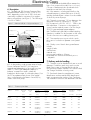
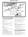
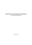
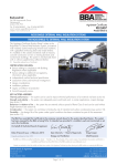
Electronic Copy
CI/SfB
(5.3)
Balmoral Group Ltd
Balmoral Park
Loirston
Aberdeen AB12 3GY
Tel: 01224 859100 Fax: 01224 859123
Agrément
Certificate
No 01/3786
e-mail: [email protected]
Designated by Government
to issue
European Technical
Approvals
Product
• THIS CERTIFICATE RELATES
TO THE BALMORAL SBR
SEWAGE TREATMENT PLANT.
• Each product is for the
treatment of domestic sewage.
• The products are for use in
conjunction with domestic
drains and public and private
sewers for the collection and
treatment of domestic sewage
as is permitted to be
discharged by the Water
Industry Act 1991, the
Sewerage (Scotland) Act 1968
and the Water and Sewage
Services (Northern Ireland)
Order 1973.
• This Certificate does not
cover the use of any of the
products for untreated trade
effluents.
BALMORAL SBR SEWAGE TREATMENT PLANT
Systèmes de traitement des aux résiduaires
Abwasseraufbereitung
Regulations
1 The Building Regulations 2000 (England and Wales)
The Balmoral SBR Sewage Treatment Plant is not subject to these
Regulations. However, in the opinion of the BBA, the product will satisfy
or contribute to satisfying the provisions under Section 59 of the
Building Act 1984.
2 The Building Standards (Scotland) Regulations 1990 (as amended)
In the opinion of the BBA, the position of the Balmoral SBR Sewage
Treatment Plant, if used in accordance with the provisions of this
Certificate, will satisfy or contribute to satisfying the various Regulations
and related Technical Standards as listed below.
Regulation:
Standards:
10
B2.1 and B2.2
The products are acceptable. See section 13 of this
Certificate.
Comment:
Regulation:
Standard:
Fitness of materials
Selection and use of materials and components
24
M2.5
Drainage and sanitary facilities
Discharges from a drainage system
The products can meet the relevant requirements of this
Technical Standard. See sections 8.1 to 8.7 of this
Certificate.
Comment:
3 The Building Regulations (Northern Ireland) 1994 (as amended)
In the opinion of the BBA, the Balmoral SBR Sewage Treatment Plant, if
used in accordance with the provisions of this Certificate, will satisfy or
contribute to satisfying the various Building Regulations as listed below.
Regulation:
B2
Regulation:
Comment:
Fitness of materials and workmanship
The products are acceptable. See section 13 of this
Certificate.
Comment:
N9
Cesspools, septic tanks and similar structures
The products can meet the relevant requirements of this
Regulation. See sections 8.1 to 8.7 of this Certificate.
4 Construction (Design and Management) Regulations 1994
Information in this Certificate may assist the client, planning supervisor,
designer and contractors to address their obligations under these Regulations.
See section:
2 Delivery and site handling.
5 The Health and Safety at Work etc Act 1974 and the Health and Safety at
work (Northern Ireland) Order 1978
In buildings subject to this Act and Order, regular maintenance is a
requirement for the Balmoral SBR Sewage Treatment Plant. See the section on
Cleaning and maintenance in this Certificate.
Readers are advised to check the validity of this Certificate by either referring to the Index of Current BBA Publications or contacting
the BBA direct (Telephone Hotline 01923 665400).
Technical Specification
Electronic6.3 Copy
In the RV an air bubble diffuser aerates the
liquor for a set period (normally four to six hours).
Colonies of bacteria are thus produced which
break down and clarify the sewage.
6 Description
6.1 The Balmoral SBR Sewage Treatment Plant
(sequential batch reactor) consists of one or two
tanks, depending on the size of SBR, which are
rotationally moulded in one piece from mediumdensity polyethylene (see Figure 1). The SBR range
is shown in Table 1.
Figure 1
6.5 The tanks incorporate 110 mm diameter inlet
and outlet sockets for connection to 110 mm
PVC-U pipework to BS EN 1401-1 : 1998 or the
BBA equivalent. Connection to other pipework
systems can be made by means of a short length
of PVC-U pipe and appropriate adaptors.
Balmoral SBR (6 + 12) general layout
reactor vessel access
desludging access
ground level
6.6 The Balmoral rotationally-moulded sampling
chamber is installed 2 m downstream on the outlet.
This also functions as a rodding/access point.
max level
batch/cycle volume ⫺
normally 1/3 daily DWF
fill
max level
6.4 After aeration, a settling period allows the
cultured bacteria to settle at the bottom of the RV
and the clarified effluent is drawn from the middle
of the RV by an air-lift pump.
6.7 The central processing unit which controls
the system is housed in a separate control panel
kiosk.
air-lift pumps
out
min level
in
discharge
buffer storage of
2/3 daily DWF
settled sludge level
minimum 12
months reactor
vessel activated
sludge storage
primary settlement
(gross solids)
bubble diffuser
6.8 Quality control checks during manufacture
include:
weight of tanks
wall thickness
material cure
position and installation of fittings
assembled units receive a final check prior to
despatch.
min level
minimum 12
months sludge storage
7 Delivery and site handling
7.1 The tanks must be handled with care to avoid
damage. On delivery and siting, tanks must be
lifted using a rope or sling passed through the
lifting points provided. The tanks must not be rolled.
Site storage should be on level ground.
6.2 In the product, crude sewage enters a large
Primary Settlement Tank (PST), this may be a
separate tank depending on the model size (see
Table 1). The PST has adequate capacity to
balance out peak flows and is where the
breakdown and storage of solids takes place. From
the PST a pre-determined volume of the settled
liquor is transferred to the Reactor Vessel (RV) by
means of an air-lift pump.
Table 1
Treatment plant data
Catalogue Population
number
served
Max drain
inlet invert
depth
Head loss
through
unit
(mm)
(mm)
(mm)
6
1000
30
2060 dia
SBR/12
12
1000
30
SBR/18
18
1000
SBR/24
24
SBR/36
SBR/48
SBR/6
7.2 Each tanks bears the manufacturer’s name,
identification number and the BBA identification
mark incorporating the number of this Certificate.
The installation instructions are attached to the tank.
Tank dimensions
Primary
Reactor
settlement
vessel
(mm)
Nominal tank volumes
Primary
Reactor
settlement
vessel
Max
desludging
interval
Vessel
weight
(litres)
(litres)
(months)
(per unit kg)
n/a
2120
2000
12
298
2380 dia
n/a
4300
3600
12
405
80
2380 dia
2380 dia
6000
6000
12
283
1000
80
2380 dia
2380 dia
6000
6000
6
285
36
1000
80
2250 dia x
2950 long
2380 dia
8000
6000
6
363
48
1000
80
2250 dia x
2950 long
2250 dia x
2950 long
8000
8000
6
443
2
Design Data
ElectronicParticular
Copy
attention should be given to the provision
of concrete backfill to resist flotation due to
groundwater.
8 General
9.3 No superimposed loads such as vehicles
should be allowed within 3 m of the tanks unless a
concrete surround or reinforced concrete slab is
designed by a qualified civil/structural engineer so
that no loads are transmitted directly on to the tank.
8.1 The Balmoral SBR Sewage Treatment
Plant is suitable for the collection and
treatment of domestic sewage from
households of up to 48 people. The appropriate
model for the population should be selected using
the details given in Table 1.
10 Resistance to chemicals
The product is resistant to the small quantities of acid,
alkali or other substances likely to be found in
normal domestic sewage or the surrounding backfill.
8.2 The general design of the installation should
be in accordance with BS 6297 : 1983.
8.3 The product should be sited as far as possible
from domestic dwellings, in accordance with the
relevant Building Regulations and BS 6297 :
1983.
11 Watertightness
The product, when correctly installed, will not allow
seepage either into or from the surrounding soil. The
pipe joints, when correctly made, will be watertight.
8.4 Groundwater and flood levels should always
be below plant outlet level, unless specific
arrangements have been made to overcome this
problem.
12 Cleaning and maintenance
12.1 Cleaning and maintenance should be
carried out in accordance with the User’s Manual
supplied with each unit. When carrying out any
work on the product it is important to observe all the
Health and Safety warnings in the User’s Manual.
8.5 The discharge from the unit must be to a
suitable sub-soil irrigation system or water course in
accordance with the requirements of the
Environment Agency or the Scottish Environment
Protection Agency.
12.2 Desludging is effected by a suction tanker,
taking care to avoid damage by the hose nozzle.
8.6 A sampling chamber should be provided at
the outlet 2 m downstream to comply with the
sampling requirements of the Environment Agency
(England and Wales) and the Scottish Environment
Protection Agency (Scotland).
Frequency of inspection
12.3 Where the system is installed and used in
situations subject to The Health and Safety at Work
etc Act 1974 and The Health and Safety at Work
(Northern Ireland) Order 1978, an inspection of
the system must be carried out every 12 months.
8.7 The treated effluent discharging from the
product will normally be to Band 2 of Table 10 of
BS 7781 : 1994 [ie suspended solids (SS) content
<30 mg per litre, Biochemical Oxygen Demand
(BOD5) <20 mg per litre], provided the hydraulic
and BOD loadings are within the manufacturer’s
specifications (see section 8.1). Under certain
conditions the effluent may not be within these
Standards. This is normal for any biological
sewage treatment process and can be caused by
unusual hydraulic or BOD loading, weather
conditions, contamination by greases, excessive
amounts and/or strength of laundry wastewater or
poisoning of the microbiological fauna and flora
by chemicals or antibiotics.
13 Durability
The structural properties of the polyethylene
from which the tank is constructed, in
common with all similar materials, will
deteriorate with time. The deterioration is
accelerated by contact with groundwater, sewage
and dissolved or suspended organic or inorganic
compounds (the resulting loss of strength and
stiffness has been taken into account in the
manufacturer’s design code). In the opinion of the
BBA, the product, when used in the context of and
installed in accordance with this Certificate, will
have a life in excess of 25 years. The mechanical
and electrical components are liable to wear
during operation, but the design layout is such that
they can be replaced as required.
8.8 Balmoral Group Ltd offer their clients a
maintenance service contract for regular inspection
and necessary maintenance of the Balmoral SBR units.
9 Strength
Installation
9.1 The manufacturer’s design has been assessed
as satisfactory. The product has adequate strength
to resist damage from minor impacts during
handling. It must be slung at the lifting points
provided (see section 7.1).
14 General
9.2 The product must be installed in accordance
with the Installation Guidelines provided with the
units (see section 14 for installation summary).
14.2 Electrical connections to the product from the
control panel must be carried out by a competent
person using material suitable for the purpose.
14.1 Balmoral Group Ltd can advise clients of the
installation requirements.
3
Electronicgravel.
Copy
As backfilling progresses the tank is filled
14.3 Electrical connections must be in strict
accordance with the manufacturer’s instruction and
the IEE Wiring Regulations — Regulations for
Electrical Installations, Sixteenth Edition 1991.
Cables must be protected from accidental
damage, eg by a suitable conduit.
with water to match the level of backfill.
Wet, poorly drained site
15.3 The base of the excavation should allow for
between 200 and 250 mm of consolidated
hardcore prior to covering with sand blinding and
a polythene membrane and a 150 mm depth of
concrete. The tank is lowered onto the freshly laid
concrete and ‘puddled’ to form a cradle.
14.4 The control panel kiosk can be sited
anywhere with access to mains electricity within a
2 m radius of the plant itself.
14.5 The product must not be installed in areas
liable to localised flooding without adequate
protection as specified by the marketing company.
15.4 The tank is filled with water to a level of 0.5 m
and the excavation is backfilled in layers of a lean
mix concrete. Concrete is essential as the backfill
material where there is a possibility of a high water
table of ground water accumulating or where the
tank is installed in non-free draining or heavy soil.
14.6 It is essential to take precautions to prevent
damage by site traffic. Superimposed loads from
vehicles, etc should not be permitted within a
distance equal to the depth of excavation, unless
suitable structural protection is provided. A fence
may be required to prevent vehicles from
approaching too close to the unit.
Backfilling
15.5 With either installation, as backfilling
progresses the tank is filled with water to match the
level of backfilling and partly balance the pressure
on the tank. Backfilling must be carefully consolidated
around the tank to ensure even transfer of soil loads
to the tank shell and to prevent localised stress
concentrations. The concrete surround must be
carefully placed and compacted around the tank.
Siting
14.7 The products should be sited so that:
• they are not prejudicial to the health of any person
• there is an adequate means of access for emptying.
14.8 Installation must be strictly in accordance
with the manufacturer’s instructions and the
recommendations of BS 6297 : 1983, when
applicable.
Note: In the six and twelve person models the internal
reactor vessel (RV) must be filled to one third of its height
with water before the outer primary settlement tank (PST)
is filled.
14.9 The excavation for the tank must be carried
out generally in accordance with BS 6031 : 1981
paying particular attention to safety procedures and
must be of sufficient size to permit easy placement
and backfilling. Allowances must be made for any
ground support system and the excavation depth
must be as specified by the manufacturer for the
appropriate size of tank.
15.6 The backfilling surround is brought up to a
level 50 mm below the inlet and outlet pipes, any
temporary pipe covers are removed and the tank is
connected with 110 mm diameter PVC-U pipes or
other suitable pipes, using adaptors as necessary.
A short length of pipe with flexible joints must be
used adjacent to the tank to allow for slight
differential movement. A vent pipe should be
installed on the outlet pipe (see Figure 2).
14.10 A dry site is defined as one where the water
table is always below the bottom of the tank and the
subsoil is well drained. A wet site is defined as where
the subsoil is of a poor draining nature, eg clay, and
therefore susceptible to holding surface water.
15.7 Backfilling is progressed to ground level with
backfill material determined by ground conditions
(see Figure 2).
Installation of control panel kiosk
15.8 A site for the kiosk must be carefully selected
within 2 m of the tank and from where the SBR
manhole lid can be seen. The ground should be
free from flooding and should not restrict access for
desludging.
14.11 To maintain the head difference between
inlet and outlet connections and in line with the
incoming drain the tank must be positioned
vertically, on a level foundation. Levelling pegs
should not be used under the tank base as damage
to the tank may result. A spirit level or surveying
level should be used to ensure the correct
positioning is achieved.
15.9 A small trench, approximately 450 mm
deep by 300 mm wide, must be excavated from
the air line outlet point on the SBR to the site of the
kiosk. A length of 110 mm diameter PVC-U drain
should be laid in the trench (preferably on a gravel
bed) and the end inserted into the grommet
provided at the SBR.
15 Procedure
Dry, well drained site
15.1 A minimum base thickness of 150 mm lean
mix concrete (minimum C7.5) to BS 5328-2 :
1997 is required. When laid, the tank is lowered
into position.
15.10 A 90° bend should be fitted at the kiosk
end and a short length of vertical pipe fitted so that
the ducting projects vertically up to the finished
ground level. After kiosk installation the pipe should
be sealed with expandable foam.
15.2 After the base has initially set, the tank is
filled with water to a level of 0.5 m and the
excavation is backfilled in layers with graded pea
4
Electronic Copy
Figure 2
Installation
measure BOD and suspended solids and the
results compared to the requirements of BS 7781 :
1994.
Technical Investigations
The following is a summary of the technical
investigations carried out on the Balmoral SBR
Sewage Treatment Plant.
17.3 The manufacturing process was examined,
including the methods adopted for quality control,
and details obtained of the quality and
composition of the materials used.
16 Tests
16.1 Tests were carried out on the tank material to
determine:
density, based on ISO 1183 : Method A : 1987
Vicat softening temperature, BS 2782-1 :
Method 120B : 1990
melt flow rate, BS 2782-7 : Method 720A : 1979
17.4 An assessment was made of the tank in
relation to:
watertightness
degredation of mechanical properties resulting from
exposure to sewage, groundwater, dissolved
salts and dilute acids or alkalis
long-term loading conditions
compliance with the guidelines given in BS 6297 :
1983 in relation to chamber sizing and
constructional details.
16.2 Tests were carried out on complete tanks to
determine:
capacity
resistance to vacuum pressure
dimensional accuracy
watertightness of connections when subjected to
angular deflection
effect of long-term exposure to internal pressure.
17.5 Visits were made to sites to assess the
practicability and ease of installation.
Bibliography
17 Other investigations
17.1 Assessments were made of the structural
calculations and assumptions used in the design of
the product and of the durability of the tank in
relation to chemical attack by effluents and
groundwater, and in relation to long-term loading.
BS 2782 Methods of testing plastics
BS 2782-1 Thermal properties
BS 2782-1 : Method 120B : 1990 Determination
of Vicat softening temperature of thermoplastics
BS 2782-7 Rheological properties
BS 2782-7 : Method 720A : 1979 Determination
of melt flow rate of thermoplastics
17.2 An examination was made of sample analyses
of effluent from the Balmoral SBR, carried out to
5
Electronicin theCopy
form in which it was current at the date of
BS 5328 Concrete
BS 5328-2 : 1997 Methods for specifying
concrete mixes
BS 6031 : 1981 Code of practice for earthworks
BS 6297 : 1983 Code of practice for design and
installation of small sewage treatment works and
cesspools
BS 7781 : 1994 Procedure for type testing of small
biological domestic wastewater treatment plants
BS EN 1401 Plastics piping systems for nonpressure underground drainage and sewerage.
Unplasticized poly(vinylchloride) (PVC-U)
BS EN 1401-1 : 1998 Specifications for pipes,
fittings and the system
ISO 1183 : 1987 Method for determining the
density and relative density of non-cellular plastics
this Certificate.
18.3 This Certificate will remain valid for an
unlimited period provided that the product and the
manufacture and/or fabricating process(es) thereof:
(a) are maintained at or above the levels which
have been assessed and found to be satisfactory
by the BBA;
(b) continue to be checked by the BBA or its
agents; and
(c) are reviewed by the BBA as and when it
considers appropriate.
18.4 In granting this Certificate, the BBA makes
no representation as to:
(a) the presence or absence of any patent or
similar rights subsisting in the product or any other
product;
(b) the right of the Certificate holder to market,
supply, install or maintain the product; and
(c) the nature of individual installations of the
product, including methods and workmanship.
Conditions of Certification
18 Conditions
18.1 This Certificate:
(a) relates only to the product that is described,
installed, used and maintained as set out in this
Certificate;
(b) is granted only to the company, firm or person
identified on the front cover — no other company,
firm or person may hold or claim any entitlement to
this Certificate;
(c) has to be read, considered and used as a
whole document — it may be misleading and will
be incomplete to be selective;
(d) is copyright of the BBA.
18.2 References in this Certificate to any Act of
Parliament, Regulation made thereunder, Directive
or Regulation of the European Union, Statutory
Instrument, Code of Practice, British Standard,
manufacturers’ instructions or similar publication,
shall be construed as references to such publication
18.5 Any recommendations relating to the use or
installation of this product which are contained or
referred to in this Certificate are the minimum
standards required to be met when the product is
used. They do not purport in any way to restate the
requirements of the Health & Safety at Work etc
Act 1974, or of any other statutory, common law
or other duty which may exist at the date of this
Certificate or in the future; nor is conformity with
such recommendations to be taken as satisfying the
requirements of the 1974 Act or of any present or
future statutory, common law or other duty of care.
In granting this Certificate, the BBA does not
accept responsibility to any person or body for any
loss or damage, including personal injury, arising
as a direct or indirect result of the installation and
use of this product.
In the opinion of the British Board of Agrément, the Balmoral SBR Sewage Treatment Plant is fit
for its intended use provided it is installed, used and maintained as set out in this Certificate.
Certificate No 01/3786 is accordingly awarded to Balmoral Group Ltd.
On behalf of the British Board of Agrément
Date of issue: 23rd March 2001
British Board of Agrément
P O Box No 195, Bucknalls Lane
Garston, Watford, Herts WD25 9BA
Fax: 01923 665301
Chief Executive
©2001
e-mail: [email protected]
website: www.bbacerts.co.uk
For technical or additional
information, tel: 01923 665300.
For information about Agrément
Certificate validity and scope, tel:
Hotline: 01923 665400