1
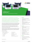
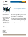
NETWORK AND SERVICE ENABLEMENT JD720C Series CellAdvisor™ Cable and Antenna Analyzers Key Benefits Key Features • Fiber inspection with pass/fail (requires P5000i microscope) • Measure RF and optical power • 3 zoom zones enable detailed spectrum analysis • RF port protection up to 40 dBm (10 W) • Supports StrataSync cloud-enabled management, analysis, reporting •Bluetooth® connection to StrataSync from cell site • Generates PDF reports • Auto-save events that exceed limits • Free Windows-based analysis and control applications: –JDViewer adds post-process, report generation, and personalized settings – JDRemote adds full instrument remote control through a software client Applications • Verify cell-site cable and antenna systems • Testing distributed radios with RF and fiber feed lines • Validation of DAS system deployments Key Measurements • Reflection — VSWR/Return Loss • DTF — VSWR/Return Loss • 1-Port Cable Loss • Smith Chart • 1-Port Phase • RF Power Meter • Optical Power Meter • Fiber Inspection website : www.jdsu.com/nse • Now you can carry a single instrument for RF and fiber • Reduce your costs using StrataSync™ to manage your assets • Easily detect signal degradation over time with Trace Overlay • Reduce test time using dual display to make two measurements simultaneously • Get instant problem notification with pass/fail analysis The majority of problems in mobile networks occur in the base station’s infrastructure, consisting of the antenna system, RF and fiber cables, and connectors. To properly service and install cell sites requires suitable test equipment. The JD720C-series analyzers are optimal test solutions for characterizing cell-site infrastructure because of their handheld design, ease of use, and rich functionality. The JD720C-series analyzers’ measurement functions can accurately verify a site’s transmission line and antenna system from signal reflections (voltage standing wave ratio [VSWR] or return loss) to RF or optical transmission power. They also accurately measure the distance to fault (DTF) for proper location identification. The instrument’s touch-panel operation and 7-inch-wide thin-film transistor (TFT) color display simplifies measurements and viewing results. Also, its application software permits easier measurement analysis and report generation. The optional fiber inspection microscope and optical power meters provide all the tools needed in a single instrument to test both RF and fiber cell sites. JD720C-SERIES CELLADVISOR CABLE AND ANTENNA ANALYZERS 2 Top view 15 V DC Port External DC input port LAN Ethernet port for the interface with JDViewer or JDRemote RF Out/Reflection RF Out/Reflection port for cable and antenna analysis USB Host USB port for memory devices, RF or optical power sensors, and P5000i Fiber Microscope USB Client USB port for the interface with JDViewer Serial Serial port for RF power sensors Front view Transflective LCD Analysis Keys Transflective touch-screen display Quickly access analysis tools Measurement Keys Conveniently displays in horizontal or vertical mode Dual Display Quickly access measurements Screen Menu Touch -screen interface for fast and easy operation Data Entry Conveniently enter numbers or data selection Backlight Illuminated key panel ideal for dark environments JD720C-SERIES CELLADVISOR CABLE AND ANTENNA ANALYZERS 3 Key Measurements Reflection measures the impedance performance of the cell-site transmission line across the selected frequency range in VSWR or return loss. • The instrument’s database includes over 80 wireless frequency bands with the ability to add more. • A user-definable limit line automatically indicates pass/fail status. • Users can set up to six markers for trace analysis. Reflection — Return Loss Distance to Fault (DTF) identifies fault locations in the cell site transmission system indicating signal discontinuities using VSWR or return loss. • Up to 1,500 m (4,921 ft) measurement distance. • High-Resolution mode with 2001 data points. • The instrument’s database includes over 95 cable types with the ability to add more. • A user-definable limit line automatically indicates pass/fail status. DTF — VSWR • Users can set up to six markers for trace analysis. 1-Port Cable Loss measures the signal loss through cables or other devices over a defined frequency range. • A user-definable limit line automatically indicates pass/fail status. • Users can set up to six markers for trace analysis. 1-Port Cable Loss Smith Chart can be used to display impedance matching characteristics in cable and antenna systems as well RF devices. Users can set up to six markers for trace analysis. Smith Chart JD720C-SERIES CELLADVISOR CABLE AND ANTENNA ANALYZERS 4 Key Measurements (Cont’d.) 1-Port Phase measures S11 phase to tune antennas and phase-match cables. Users can set up to six markers for trace analysis. Power Meter functions easily and comprehensively measure power using external power sensors and meters. 1-Port Phase • JD72450551/2: economic RF power sensors via serial connection • JD730 Series: high-precision RF power sensors via USB connection • MP-60/MP-80: optical power meters via USB connection Power Sensors The power meter displays either the RF/optical power level in two formats: as a realtime power level value in an analog meter and as a power level trend through time in a histogram chart. Its configurable settings include display range, maximum and minimum limits, and power units in dBm or watts. Users can set minimum and maximum power limits to automatically indicate pass/ fail status. Power Meter Fiber Inspection Fiber Inspection eliminates the most common fiber link problems by verifying that connectors are not contaminated. Only the JD720C-series analyzers can quickly and easily troubleshoot and certify fiber connection quality and cleanliness. Connecting the optional P5000i Fiber Microscope lets users quickly inspect and clean fiber connections with a clear pass/fail indication. The free FiberChekPRO application can be used on a PC/laptop with the P5000i microscope to perform the same fiber analysis in parallel using the instrument to test RF and using the PC/laptop to test fiber. Users also can inspect, test, and certify any fiber connector and instantly generate comprehensive pass/fail summary reports. JD720C-SERIES CELLADVISOR CABLE AND ANTENNA ANALYZERS 5 Key Benefits Designed for Field Use The compact, lightweight JD720C-series analyzers are especially convenient for users performing measurements in the field. The analyzers weigh less than 2.35 kg fully loaded and include a lithium ion (LiON) battery that lasts more than 7.5 hours. Its portability lets users take it anywhere, even to the top of a tower. Its transflective display can be set for outdoor mode for viewing measurements in direct sunlight. Also, its backlit key panel with Night-Display mode makes it easy to use in the dark. The JD720C-series analyzers can operate in temperatures ranging from –10 to 55°C; and its rugged bumper design protects it if it is dropped or if it receives an external impact that exceeds the MIL-PRF-28800F class 2 specification. Outdoor Display mode provides easier reading in direct sunlight Quickly Sweeps It can perform measurements in less than 0.8 ms/point, making these the fastest cable and antenna analyzers on the market with uncompromising fast sweep speed in DualDisplay mode. Easy to Use Favorite Users can create favorite keys as a shortcut to conveniently access repeatedly used measurements rather than configuring them each time, reducing steps and completing tasks quicker and more efficiently. They can add editable key words to quickly create unique file names and can generate a PDF report directly from the instrument. The Quick Save hard key lets users simultaneously save a trace file and a screen file. If two measurements are displayed on the screen at once, it generates two trace files, one for each screen. Multilanguage User Interface The instruments’ architecture can incorporate different languages into the menu structure for localization worldwide. Key words Bluetooth Connectivity (Option 003) This option provides remote control and monitoring capability using JDRemote software via Bluetooth. Users can also transfer files from the instrument using file transfer. Users can also tether the instrument to an Android smartphone or tablet with a data service connection to upload or download data to the JDSU StrataSync cloud. Bluetooth connectivity JD720C-SERIES CELLADVISOR CABLE AND ANTENNA ANALYZERS 6 Key Benefits (Cont’d.) JDViewer Features The JDViewer application software provides all of the necessary tools to operate these instruments more conveniently including: • Quickly exchange data via USB or LAN connection • Retrieve or save measurements • Export measurement results • Analyze measurement results, assigning multiple makers and limit lines • Register or edit user-definable frequency bands and cable types JDViewer VSWR, DTF, cable loss, and Smith chart • Easily compare measurement results • Convert VSWR-DTF • Access available report templates • The ability to generate and print reports Analyzer with JDRemote Expand Capabilities with Essential Fiber Handling Tools • Optical power meter (MP series) • Fiber inspection and pass/fail analysis with P5000i Fiber Microscope MP-60/MP-80 P5000i Microscope StrataSync The JD720C-series analyzers are compatible with the JDSU StrataSync cloud to manage instrument inventory and to locate all equipment and to identify which engineer is using it. StrataSync also helps to keep instruments current through remote upgrades to ensure all instruments have the latest firmware. It also centralizes configuration setting and distribution to ensure that engineers are using the same instrument settings to achieve consistent measurements. Once testing is complete, measurement results can be uploaded into StrataSync for secure storage and sharing. Engineers who are unable to resolve a problem can share measurement results with an expert to get analysis help from anywhere without having the expert be near the instrument. • Asset inventory management • Remotely distribute instrument upgrades • Centralized configuration sharing • Test data management – Trace files –Screenshots – Remote analysis JD720C-SERIES CELLADVISOR CABLE AND ANTENNA ANALYZERS 7 Key Features Trace Overlay Users can compare and analyze up to four traces by superimposing them onto one measurement display. Additionally, they can set up to six markers on any trace independently. Zoom Zones Trace Overlay User-definable zones on frequency sub-bands let users visually identify uplink and downlink frequencies to verify compliance within a single measurement window for closer analysis of user-definable zones in separate windows. Alternate Sweep in DTF Users can perform two independent sweeps, such as a reflection measurement and a DTF measurement. Zoom Zones Dual Display The ability to display two measurements simultaneously, even if performed independently, reduces test time. Alternate Sweep Dual Display JD720C-SERIES CELLADVISOR CABLE AND ANTENNA ANALYZERS 8 Key Features (Cont’d.) Limit Lines Limit lines let users set variable thresholds to control the parameters that define whether a test passes or fails. Either exceeding the set limit or falling below it will show a failed test result. Users can also set a user-defined limit, and if any measurements fall outside of the area define, it will also result in a failed test. Standard limit line Straight line with gap The standard limit line extends over the full signal spectrum and can be configured to indicate a fail when the measurement exceeds the threshold. Users also can set this limit line to measure only specific sections of the spectrum, and any sections exceeding the set threshold will indicate a fail. Multisegment limit line (MSL) MSLs let users set upper- and lower-level parameter limit lines on both sides of the spectral signal, providing more flexibility than a single straight line. Measurements that fall within the boundaries of these lines will pass, while measurements that exceed the upper line or fall below the lower one will fail. Multisegment limit line with upper and lower Window Limit Users can define an area on the chart to help refine the test criteria, and measurements that fall within the area selected will pass. This capability is useful for tuning devices or antennas in real time, because it shows how adjustments affect the signal on the screen. Help Function Window limit Help The Help function gives users task-based information in real time. Being able to easily browse or search topics for specific information improves productivity and reduces the number of inquiries. JD720C-SERIES CELLADVISOR CABLE AND ANTENNA ANALYZERS 9 Specifications* Frequency Range JD723C JD724C Resolution Accuracy 100 MHz to 2.7 GHz 5 MHz to 4 GHz 10 kHz < ±25 ppm at 25°C RF Power Meter General Parameter Display range Offset range Resolution –80 to +120 dBm 0 to 60 dB 0.01 dB or 0.1 x W (x = m, u, p) Data Points External RF Power Sensors 126, 251, 501, 1001, 2001 JD731B Directional Power Sensor Frequency range 300 MHz to 3.8 GHz Dynamic range 0.15 to 150 W (average) 4 to 400 W (peak) Type-N female on both ends Connector type Measurement type Forward/reverse average power, forward peak power, VSWR Accuracy ±(4% of reading +0.05 W)1,2 JD733A Directional Power Sensor Frequency range 150 MHz to 3.5 GHz Dynamic range 0.1 to 50 W (average) 0.1 to 50 W (peak) Connector type Type-N female on both ends Measurement type Forward/reverse average power, forward peak power, VSWR Accuracy ±(4% of reading +0.05 W)1,2 JD732B Terminating Power Sensor Frequency range 20 MHz to 3.8 GHz Dynamic range –30 to +20 dBm Connector type Type-N male Measurement type Average Accuracy±7%1 JD734B Terminating Power Sensor Frequency range 20 MHz to 3.8 GHz –30 to +20 dBm Dynamic range Connector type Type-N male Measurement type Peak Accuracy±7%1 JD736B Terminating Power Sensor Frequency range 20 MHz to 3.8 GHz Dynamic range –30 to +20 dBm Connector type Type-N male Measurement type Average and peak Accuracy±7%1 Optical Power Meter Display range –100 to +100 dBm Offset range 0 to 60 dB Resolution 0.01 dB or 0.1 mW Measurement Speed Reflection DTF < 0.7 ms/point < 0.8 ms/point Measurement Accuracy Corrected directivity Reflection uncertainty 40 dB (typical) ±(0.3 + |20log (1 + 10-EP/20)|) (typical) EP = directivity – measured return loss Output Power 0 dBm (nominal) Interference Immunity On channel On frequency +15 dBm (nominal) +5 dBm (nominal) Measurements Reflection (VSWR) VSWR range 1 to 65 Return loss range 0 to 60 dB Resolution0.01 DTF Vertical VSWR range 1 to 65 Vertical return loss range 0 to 60 dB Vertical resolution 0.01 Horizontal range 0 to (# of data points – 1) x horizontal resolution Maximum = 1500 m (4921 ft) Horizontal resolution (1.5 x 10⁸) x (VP)/delta VP = propagation velocity delta = stop frequency – start frequency (Hz) Cable Loss (1 Port) Range 0 to –30 dB Resolution 0.01 dB 1-Port Phase Range –180 to +180° Smith Chart Resolution0.01 *Specifications for JD720C-series analyzers apply under these conditions: • Cable and antenna measurement applies after calibrating to the OSL standard. • The instrument is operating within a valid calibration period. • Data with no tolerance are considered typical values. –Typical value: Expected instrument performance operating under 20 to 30°C at 15 minutes sustained –Nominal value: A general, descriptive term or parameter. JD720C-SERIES CELLADVISOR CABLE AND ANTENNA ANALYZERS 10 Specifications continued External Optical Power Meters Battery MP-60 Optical Power Meter Wavelength range 780 to 1650 nm +10 dBm Max. permitted input level Connector input Universal 2.5 and 1.25 mm Accuracy±5% MP-80 Optical Power Meter Wavelength range 780 to 1650 nm Max. permitted input level +23 dBm Connector input Universal 2.5 and 1.25 mm Accuracy±5% Type Operation time Charge time Charging temperature Discharging temperature Storage temperature4 General information Reflection/RF Out ConnectorType-N(f) Impedance 50 Ω (nominal) Damage level >+40 dBm, ±50 V DC (nominal) Connectivity USB USB host1 USB client2 LAN Serial Type A, 2 ports Mini B, 1 port RJ45, 10/100Base-T 9-pin D-SUB male3 Display Type Size Resolution Resistive touch screen 7-inch, LED backlight, transflective LCD 800 x 480 10.8 V, 7800 mA/hr (LiON) >7.5 hours (typical) 3 hr (80%), 5 hr (100%) 0 to 45°C (32 to 104°F) ≤85% RH –20 to 55°C (4 to 131°F) ≤85% RH 0 to 25°C (32 to 77°F) ≤95% RH (noncondensing) Data Storage Internal5 External6 Minimum 120 MB Limited by size of USB flash drive Environmental AC power Battery Maximum humidity Shock and vibration Storage temperature7 0 to 40°C (32 to 104°F) with no derating 0 to 40°C (32 to 104°F) at charging –10 to 55°C (14 to 131°F) at discharging 95% RH (noncondensing) MIL-PRF-28800F Class 2 –40 to 80°C (–40 to 176°F) EMC IEC/EN 61326-1:2006 (complies with European EMC) Weight and Size (with battery) Size (W x H x D) Weight (with battery) 260 x 190 x 60 mm (10.2 x 7.5 x 2.4 in) < 2.35 kg (5.18 lb) Warranty 2 years Speaker Calibration Cycle Built-in speaker 2 years Power External DC input 12 to 15 V DC Power consumption 12 W 37.5 W maximum (when charging battery) External AC power adapter Input 100 to 250 V 50 to 60 Hz, 1.2 A Output 15 V DC, 3 A 1. Connects flash drive, power sensor, or P5000i 2. Connects to PC/laptop for data transfer 3. For JD72450551/50552 4. 20 to 85% RH, store battery pack in low-humidity environment; extended exposure to temperatures above 45°C could significantly degrade battery performance and life 5. Up to 3800 traces 6. Supports USB 2.0 compatible memory devices 7. With the battery pack removed JD720C-SERIES CELLADVISOR CABLE AND ANTENNA ANALYZERS 11 Ordering Information Basic Model1 Description 100 MHz to 2.7 GHz 5 MHz to 4 GHz Part Number JD723C JD724C Options NOTE: Upgrade options for the JD720C use the designation JD720CU before the respective last three-digit option number. Part Number Description Bluetooth connectivity JD720C003 USB GPS connectivity JD720C004 Standard Accessories Description Part Number JD720C soft carrying case2JD72050541 AC/DC power adapter2GC72450522 Cross LAN cable (1.5 m)2G710550335 USB A to Mini B cable (1.8 m) GC72450536 > 1 GB USB memory2GC72450518 Automotive cigarette lighter/12 V DC adapter2GC72450523 Rechargeable LiON battery2G710550325 Stylus2G710550316 JD720C-Series user’s manual and application software CD JD72050561 Optional Calibration Kits Description Y - Calibration Kit, Type-N(m), DC to 4 GHz, 50 Ω Y - Calibration Kit, DIN(m), DC to 4 GHz, 50 Ω Part Number JD72450509 JD72450510 Optional RF Cables Description 1.0 m (3.28 ft) RF cable, DC to 18 GHz, Type-N(m) to Type-N(m), 50 Ω 1.5 m (4.92 ft) RF cable, DC to 18 GHz, Type-N(m) to Type-N(f), 50 Ω 3.0 m (9.84 ft) RF cable, DC to 18 GHz, Type-N(m) to Type-N(f), 50 Ω Part Number G710050530 G710050531 G710050532 Optional RF Power Sensors Description Part Number Directional power sensor (peak and average), 300 MHz to 3.8 GHz, JD731B average 0.15 to 150 W, peak 4 to 400 W Directional power sensor (peak and average), 150 MHz to 3.5 GHz, JD733A average/peak 0.1 to 50 W Terminating power sensor (average), 20 MHz to 3.8 GHz, JD732B –30 to +20 dBm Terminating power sensor (peak), 20 MHz to 3.8 GHz, JD734B –30 to +20 dBm Terminating power sensor (peak and average), 20 MHz to 3.8 GHz, JD736B –30 to +20 dBm Terminating power sensor (average), 40 MHz to 3 GHz, JD72450551 –30 to 0 dBm Terminating power sensor (peak), 40 MHz to 4 GHz, –40 to 0 dBm JD72450552 Optional RF Adapters Description Adapter Type-N(m) to DIN(f), DC to 4 GHz, 50 Ω Adapter DIN(m) to DIN(m), DC to 4 GHz, 50 Ω Part Number G710050571 G710050572 Adapter Type-N(m) to SMA(f), DC to 18 GHz, 50 Ω G710050573 Adapter Type-N(m) to BNC(f), DC to 1.5 GHz, 50 Ω G710050574 Adapter Type-N(f) to Type-N(f), DC to 4 GHz, 50 Ω G710050575 Adapter Type-N(m) to DIN(m), DC to 4 GHz, 50 Ω G710050576 Adapter Type-N(f) to DIN(f), DC to 4 GHz, 50 ΩG710050577 Adapter Type-N(f) to DIN(m), DC to 4 GHz, 50 Ω G710050578 Adapter DIN(f) to DIN(f), DC to 4 GHz, 50 Ω G710050579 Optional Optical Power Meters and Fiber Microscope Kits Description USB Optical Power Meter with software, 2.5 mm and 1.25 mm interfaces, 30-inch USB extender, and carrying pouch USB Optical Power Meter — High power, with software, 2.5 mm and 1.25 mm interfaces, 30-inch USB extender, and carrying pouch KIT: FBP-P5000i Digital Probe, FiberChekPRO software, case, and tips (FBPT-SC, FBPT-LC, FBPT-U25M, FBPT-U12M) KIT: FBP-P5000i Digital Probe, FiberChekPRO software, case, and tips (FBPT-SC, FBPT-SC/APC, FBPT-FC, FBPT-LC, FBPT-U25M, FBPT-U25MA,FBPT-U12M) KIT: FBP-P5000i Digital Probe, MP-60A USB Power Meter, FiberChekPRO software, case, tips, and adapters (FBPT-SC, FBPT-LC, FBPT-U25M, FBPT-U12M) KIT: FBP-P5000i Digital Probe, MP-60A USB Power Meter, FiberChekPRO software, case, tips, and adapters (FBPT-SC, FBPT-LC, FBPT-U25M, FBPT-U12M), and cleaning materials KIT: FBP-P5000i Digital Probe, MP-60A USB Power Meter, FiberChekPRO software, case, tips, and adapters (FBPT-SC, FBPT-LC, FBPT-U25M, FBPT-U12M) Part Number MP-60A MP-80A FBP-SD101 FBP-MTS-101 FIT-SD103 FIT-SD103-C FIT-SD113 Optional Accessories Description Attenuator 40 dB, 100 W, DC to 4 GHz (unidirectional) JD720 hard carrying case Hard carrying case with wheels CellAdvisor backpack carrying case External battery charger USB Bluetooth dongle and dipole antenna 5 dBi USB GPS receiver JD720C-series user’s manual, printed version Part Number G710050581 JD72350542 JD70050342 JD70050343 G710550324 JD70050006 JD72050005 JD720C362 StrataSync Description StrataSync Asset Management annual subscription for CellAdvisor CAA StrataSync Test Data Management annual subscription for CellAdvisor CAA3 Part Number STRATASYNC-AM-CA-CAA-1Yr STRATASYNC-TDM-CA-CAA-1Yr Warranty and Calibration Description Warranty extension of 1 year for Asia, North America Warranty extension of 1 year for Latin America, EMEA Calibration service for Asia, North America Calibration service for Latin America, EMEA 1. Requires a calibration kit 2. Standard accessories can be purchased separately 3. Requires STRATASYNC-AM-CA-CAA-1Yr Part Number JD720C200 JD720C201 JD720C250 JD720C251 JD720C-SERIES CELLADVISOR CABLE AND ANTENNA ANALYZERS Network and Service Enablement Regional Sales NORTH AMERICA TOLL FREE: 1 855 ASK-JDSU 1 855 275-5378 LATIN AMERICA TEL: +1 954 688 5660 FAX: +1 954 345 4668 ASIA PACIFIC TEL: +852 2892 0990 FAX: +852 2892 0770 EMEA TEL: +49 7121 86 2222 FAX: +49 7121 86 1222 Product specifications and descriptions in this document subject to change without notice. © 2014 JDS Uniphase Corporation www.jdsu.com/nse 30173185 003 0214 JD720C.DS.CPO.TM.AE February 2014