1
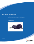
Westover FBP Probe Microscope & HD3 Display Handheld video probe microscope and display for fiber inspection User Manual ZP-PKG-0346 REV 3 REV 0 Notice Copyright Trademarks Every effort was made to ensure that the information in this document was accurate at the time of printing. However, information is subject to change without notice, and JDSU reserves the right to provide an addendum to this document with information not available at the time that this document was created. © Copyright 2008 JDSU, LLC. All rights reserved. JDSU, Enabling Broadband and Optical Innovation, and its logo are trademarks of JDSU, LLC. All other trademarks and registered trademarks are the property of their respective owners. No part of this guide may be reproduced or transmitted electronically or otherwise without written permission of the publisher. JDSU is a trademark of JDSU in the United States and other countries. CleanBlast is a registered trademark of JDSU. RibbonDrive is a trademark of JDSU. Hirose is a trademark of Hirose Electric Group. MTP is a registered trademark of US Conec, Ltd. IBC is a trademark of US Conec, Ltd. Molex is a registered trademark of Molex Incorporated. OptiTip is a trademark of Corning Incorporated. Sony is a registered trademark of Sony Corporation. Specifications, terms, and conditions are subject to change without notice. All trademarks and registered trademarks are the property of their respective companies. Patents RibbonDrive Tips: US Patent No. 6,751,017 / 6,879,439 CleanBlast: US Patent No. 7,232.262 Tested Equipment All pre-qualification tests were performed internally at JDSU, while all final tests were performed externally at an independent, accredited laboratory. This external testing guarantees the unerring objectivity and authoritative compliance of all test results. JDSU's Commerce and Government Entities (CAGE) code under the North Atlantic Treaty Organization (NATO) is 0L8C3. FCC Information Electronic test equipment is exempt from Part 15 compliance (FCC) in the United States. European Union Electronic test equipment is subject to the EMC Directive in the European Union. The EN61326 standard prescribes both emission and immunity requirements for laboratory, measurement, and control equipment. This unit has been tested and found to comply with the limits for a Class A digital device. Independent Laboratory Testing 2 This unit has undergone extensive testing according to the European Union Directive and Standards. User Manual Table Of Contents Chapter 1 JDSU FIBER INSPECTION SOLUTIONS............................................................................... 5–6 Chapter 2 INSPECT BEFORE YOU CONNECT....................................................................................... 5 Simple Solution........................................................................................................................ 5 Good Fiber Connection......................................................................................................... 6 JDSU Fiber Inspection & Cleaning Solutions................................................................. 6 Benefits of Proactive Inspection........................................................................................ 6 Fiber Optic Connectors................................................................................................7–10 Key Terms & Concepts............................................................................................................ 7 Fiber Connector (Simplex)................................................................................................... 7 Fiber Connection (Simplex)................................................................................................. 7 Body............................................................................................................................................. 8 Ferrule.......................................................................................................................................... 8 Fiber............................................................................................................................................. 8 Cladding........................................................................................................................... 8 Core................................................................................................................................... 8 Simplex & Multi-fiber Connectors..................................................................................... 8 Contamination......................................................................................................................... 9 Zones.........................................................................................................................................10 Zones Overlays............................................................................................................10 Acceptance Criteria...............................................................................................................10 Single-mode.................................................................................................................10 Multimode.....................................................................................................................10 Westover FBP Probe & HD3 Display 3 Contents Chapter 3 Westover FBP Probe Microscope....................................................................... 11–12 Introduction............................................................................................................................11 Controls.....................................................................................................................................12 Focus Control...............................................................................................................12 Magnification Control...............................................................................................12 Specifications..........................................................................................................................12 Analog Probe Models...........................................................................................................12 Chapter 4 Inspection Tips & Adapters..................................................................................... 13–15 Chapter 5 Introduction............................................................................................................................13 Barrel Assemblies..................................................................................................................13 Standard Tips..........................................................................................................................14 Long Reach Tips.....................................................................................................................14 APC Tips....................................................................................................................................14 Angled Tips..............................................................................................................................14 RibbonDriveTM Tips................................................................................................................14 Alignment Guides.................................................................................................................14 FMA Adapters.........................................................................................................................14 FBPT Tip Installation Guide................................................................................................15 FBPT Standard Inspection Tips Matrix...........................................................................15 FBPT RibbonDriveTM Inspection Tips Matrix.................................................................16 Westover HD3 Display................................................................................................. 17–20 Introduction............................................................................................................................17 HD3 Features...........................................................................................................................18 Controls.....................................................................................................................................18 Specifications..........................................................................................................................19 Charging the Battery............................................................................................................19 Changing the Battery...........................................................................................................20 Power Modes..........................................................................................................................20 Hanging Accessory...............................................................................................................21 Appendix A JDSU Fiber Inspection Video Probe Solutions.................................................22 Appendix B JDSU CleanBlast® Systems...............................................................................................23 4 User Manual JDSU Fiber Inspection Solutions Chapter 1 JDSU Fiber Inspection Solutions 1 Inspect Before you ConnectSM Contamination is the #1 source of troubleshooting in optical networks. A single particle mated into the core of a fiber can cause significant back reflection, insertion loss, and equipment damage. Visual inspection is the only way to determine if fiber connectors are truly clean before mating them. Simple Solution By implementing a SIMPLE yet IMPORTANT process of proactive visual inspection and cleaning, you can prevent poor signal performance and equipment damage. Westover FBP Probe & HD3 Display 5 Chapter 1 Good Fiber Connection JDSU Fiber Inspection Solutions There are 3 basic principles that are critical to achieving an efficient fiber optic connection: 1. 2. 3. Perfect Core Alignment Physical Contact Pristine Connector Interface Light Transmitted CLADDING CORE CLEAN CONNECTION Today’s connector design and production techniques have eliminated most of the challenges to achieving CORE ALIGNMENT and PHYSICAL CONTACT. What remains challenging is maintaining a PRISTINE END FACE. JDSU Fiber Inspection & Cleaning Solutions Benefits of Proactive Inspection 6 The JDSU video fiber inspection probe and handheld display system is used to quickly and easily inspect connector end faces, which ultimately minimizes loss and optimizes test conditions. WESTOVER FBP series video probes, available in digital or analog and single or dual-magnification (200/400X) models are high-performance, handheld microscopes designed for inspecting both “female” (bulkhead) and “male” (patch cord) connectors, as well as other optical devices. The probe microscope can also be combined with a USB converter module to inspect connectors via compatible test platforms and PC/laptop. Our versatile systems offer a wide range of configurable solutions that can meet the demands of any application. • Reduce Network Downtime • Reduce Troubleshooting • Optimize Signal Performance • Prevent Network Damage User Manual Fiber Optic Connectors Chapter 2 Fiber Optic Connectors 2 Key Terms & Concepts Fiber connectors enable fiber-to-fiber mating by aligning the two optical fibers. Fiber connectors come in various types and have different characteristics for use in different applications. The main components of a fiber connector are detailed below: Body Fiber Connector (Simplex) Fiber Ferrule Fiber Ferrule Alignment Sleeve Fiber Connection (Simplex) Physical Contact Westover FBP Probe & HD3 Display 7 Fiber Optic Connectors Chapter 2 Body Houses the ferrule that secures the fiber in place; utilizes a latch and key mechanism that aligns the fiber and prevents the rotation of ferrules of two mated connectors. Ferrule Thin cylinder where the fiber is mounted and acts as the fiber alignment mechanism; the end of the fiber is located at the end of the ferrule. Fiber CLADDING Glass layer surrounding the core, which prevents the signal in the core from escaping. CORE The critical center layer of the fiber; the conduit that light passes through. Ferrule Cladding Body Core Simplex & Multi-fiber Connectors Simplex Fiber Connector A simplex fiber connector contains a single fiber located in the center of the ferrule. Common types include SC, LC, FC and ST. Ferrule Simplex Fiber Connector Fiber Multi-fiber Connector A multi-fiber/ribbon fiber connector contains multiple linear fibers (4, 8, 12, 24, 48 or 72) in a single connector to provide high-density connectivity. The most common configuration is MPO (also called the MTP®). 8 User Manual Ribbon Fiber Connector Multiple Fibers Fiber Optic Connectors Contamination Chapter 2 Dirt is everywhere, and a typical dust particle (2–15μm in diameter) can significantly affect signal performance and cause permanent damage to the fiber end face. Most field test failures can be attributed to dirty connectors, and most of them are not inspected until the problem is detected, AFTER permanent damage has already occurred. If dirt particles get on the core surface the light becomes blocked, creating unacceptable insertion loss and back-reflection. Furthermore, those particles can permanently damage the glass interface, digging into the glass and leaving pits that create further back-reflection if mated. Also, large particles of dirt on the cladding layer and/or the ferrule can introduce a barrier that prevents physical contact and creates an air gap between the fibers. To further complicate matters, loose particles have a tendency to migrate. Scratches are typically created during polishing, cleaning or mishandling fiber connectors. Scratches that touch the core are problematic because they create back reflection. Clean Connection Light Transmitted Light Transmitted CLADDING CORE Dirty Connection CLEAN CONNECTION CORE CLADDING BACK REFLECTION DIRTY CONNECTION Clean Fiber Dirt / Contamination Pits / Chips Scratch Westover FBP Probe & HD3 Display INSERTION LOSS 9 Fiber Optic Connectors Chapter 2 Zones Zones are a series of concentric circles that identify areas of interest on the connector end face. The inner-most zones are more sensitive to contamination than the outer zones. Zones Overlays A B C D A. Core B. Cladding C. Adhesive/Epoxy D. Contact/Ferrule Single-mode Acceptance Criteria Multimode Acceptance Criteria are a series of failure thresholds that define contamination limits for each zone. The tables below list the ACCEPTANCE CRITERIA standardized by the International Electrotechnical Commission (IEC) for single-mode and multimode connectors as documented in IEC 61300-3-35 Ed. 1.0. Single-Mode MultiMode 10 Zone Name (Diameter) Scratches Defects A. Core Zone (0–25μm) none none B. Cladding Zone (25–120μm) no limit <= 3μm none > 3μm no limit < 2μm 5 from 2–5μm none > 5μm C. Adhesive Zone (120–130μm) no limit no limit D. Contact Zone (130–250μm) no limit none => 10μm Zone Name (Diameter) Scratches Defects A. Core Zone (0–65μm) no limit <= 5μm 0 > 5μm 4 <= 5μm none > 5μm B. Cladding Zone (65–120μm) no limit <= 5μm 0 > 5μm no limit < 2μm 5 from 2–5μm none > 5μm C. Adhesive Zone (120–130μm) no limit no limit D. Contact Zone (130–250μm) no limit none => 10μm User Manual WESTOVER FBP Probe Microscope Chapter 3 Westover FBP Probe Microscope 3 Introduction JDSU's Westover FBP Series Probe Microscopes are portable video microscopes used to inspect fiber optic connectivity. While most fiber microscopes are limited to inspecting “male” connectors, JDSU's WESTOVER FBP Probe is designed to inspect both simplex and multi-fiber (ribbon) types of both “male” and “female” connectors as well as optical devices, such as transceivers. The probe is specially designed to fit and operate comfortably and easily in-hand, allowing the user to inspect hardto-reach connectors that are installed on the backside of patch panels or inside hardware devices. This eliminates the need to disassemble hardware devices prior to inspection. Westover FBP Probe & HD3 Display 11 WESTOVER FBP Probe Microscope Chapter 3 Controls The basic design of the WESTOVER FBP probe microscope incorporates an imaging system, integrated light source, video camera, focus mechanism and magnification control. The probe is fully assembled and is powered by the display device. The only assembly required by the user is the connection to the display device and installation of the appropriate barrel assembly and/or the inspection tip. The FBP analog probe is equipped with a 4-pin circular Hirose™ connector with notch-keys which allows for a secure and firm latch-lock connection to the display device. Inspection Tip Barrel Assembly Focus Control Magnification Control (Dual-Mag Probes Only) 12 Focus Control The Focus Control on the probe allows the user to adjust focus manually of the live fiber end face image on the display. Magnification Control The Magnification Control (available only on dual-magnification probes) allows the user to switch between LOW and HIGH magnifications of the fiber end face image. Specifications Dimensions Weight Cord Length Connector Camera Type Video Output Light Source Lighting Technique Power Source 14.0cm x 4.6cm x 4.4cm 180g 240cm 4-pin Hirose™ male 1/3” CMOS Sensor NTSC or PAL Blue LED, 100,000+ hour life Coaxial from the display device or USB module Analog Probe Models FBP-P1 FBP-P1-400 FBP-P5 Analog, Single (LOW, 200X) Mag, NTSC Analog, Single (HIGH, 400X) Mag, NTSC Analog, Dual (LOW & HIGH, 200/400X) Mag, NTSC User Manual FBPT Inspection Tips & Adapters Chapter 4 FBPT Inspection Tips & Adapters 4 Introduction JDSU’s comprehensive selection of over 250 precision, stainless-steel fiber inspection tips and adapters will inspect every connector and application. Our unique optics architecture and design provide true versatility and adaptability, and designed and engineered for consistent and accurate inspection. These connector-specific and universal inspection tips are interchangeable, which allow the probe to interface with different types of fiber connectors. Barrel Assemblies The barrel assembly houses the objective lens and works in conjunction with a number of tips. NOTE: Certain tips are equipped with integrated optics and do not require a barrel assembly (e.g., Long Reach Tips [FBPT-LC-L], Angled Tips [FBPT-SC-A6]). FBPP-BAP1 Westover FBP Probe & HD3 Display FBPP-BAP2 FBPP-BAP3 13 FBPT Inspection Tips & Adapters Chapter 4 FBPT-SC (Bulkhead) FBPT-U25M (Patch Cord) FBPT-LC-L FBPT-SC-APC FBPT-SC-A6 FBPT-MTPA FBPT-A801-2-001-R Standard Tips (Bulkhead & Patch Cord) Standard bulkhead tips allow the user to inspect the fiber end-face on the “female” side of the bulkhead (e.g., inside hardware devices or on the back side of patch panels). Standard patch cord tips allow inspection of “male” ends of a fiber connection (e.g., patch cords, pigtails, etc.). “Universal” tips include the FBPT-U25M, compatible with 2.5mm ferrules (e.g., FC, SC, ST) and the FBPT-U12M, used to inspect 1.25mm ferrules (e.g., LC, MU). Long Reach Tips Long reach tips have a 1/2” longer reach than standard tips, and allow the user to inspect the fiber end-faces in tight, hard-to-reach spaces. Apc Tips APC tips are designed with an angle that complements the end face of an APC polish fiber connector. This allows the entire fiber image to stay in focus during inspection. Angled Tips Angled tips, identified by “A6,” are angled 60° to allow easy maneuvering and inspection of hard-to-reach locations such as transceivers on a printed circuit board (PCB) or bulkheads located in tight spaces. ribbonDriveTM Tips JDSU's patented RibbonDrive™ tips are specialty tips that allow inspection of high-density, multifiber array connectors that are mounted within a bulkhead adapter. Each tip mates securely with connectors using a precision-keyed mating adapter interface. The patented “panning knob” allows the user to view each fiber individually in the linear array. Alignment Guides Alignment guides enable the inspection of various military & aerospace connectors that use a plug & receptacle design. In addition to providing an alignment channel for sockets, these alignment guides work in conjunction with a barrel assembly to prevent the pins from breaking. FMA Adapters FMA Adapters provide optimized inspection for “male” connector ends and are ideal for inspecting patch cords with multi-fiber ribbon and APC polish connectors. FMA adapters can be utilized by a probe microscope with a universal flare adapter (FBPT-UFMA). 14 User Manual FBPT Inspection Tips & Adapters FBPT Tip Installation Guide Chapter 4 Long Reach Tips Patch Cord Adapters 60° Angled Tips Standard Patch Cord Tips RibbonDrive™ Tips Standard Bulkhead Tips Barrel Assembly JDSU offers a comprehensive selection of over 250 tips and adapters that will to inspect every connector and application. FBPT STANDARD Inspection tips (common tips shown) Connector Type Inspection Tip SC/UPC FBPT-SC Inspect SC/UPC connectors through a bulkhead. FBPT-U25M Inspect 2.5mm UPC patch cord connectors. FBPT-SC-APC Inspect SC/APC connectors through a bulkhead. FBPT-U25MA Inspect 2.5mm APC patch cord connectors. FBPT-LC Inspect LC/UPC connectors through a bulkhead. FBPT-U12M Inspect 1.25mm UPC patch cord connectors. FBPT-LC-L Inspect LC/UPC connectors through a bulkhead with 1/2” longer reach. FBPT-LC-APC Inspect LC/APC connectors through a bulkhead. FBPT-U12MA-SF Inspect 1.25mm APC patch cord connectors. SC/APC LC/UPC LC/APC Application Westover FBP Probe & HD3 Display Description 15 Chapter 4 FBPT Inspection Tips & Adapters FBPT STANDARD Inspection tips Connector Type Inspection Tip Application Description ST/ UPC FBPT-ST Inspect ST/UPC connectors through a bulkhead. FBPT-ST-A6 Inspect ST/UPC connectors through a bulkhead at a 60° angle. FC/ UPC FBPT-FC Inspect FC/UPC connectors through a bulkhead. FC/ APC FBPT-FC-APC Inspect FC/APC connectors through a bulkhead. E2000/ APC FBPT-E2000 Inspect E2000/APC connectors through a bulkhead. FBPT Multi-fiber RibbonDriveTM Inspection tips Connector Type Inspection Tip MTP®/UPC FBPT-MTP-A6 Inspect MTP®/UPC connectors through a bulkhead at a 60° angle. MTP®/APC FBPT-MTPA-L Inspect MTP®/APC connectors through a bulkhead (long reach). MTP® Patch Cords FMA-MTPA & FBPT-UFMA Inspect MTP®/UPC or APC patch cords (MTP®/APC inspection shown). FCLT-MTP-MA Inspect MTP®/UPC or APC patch cords (MTP®/APC inspection shown). 16 User Manual Application Description WESTOVER HD3 Display Chapter 5 Westover HD3 Display 5 Introduction The WESTOVER HD3 Display combines performance and value in a small formfactor device. It is designed for ultimate portability and incorporates features that enable comfort and efficiency. It features a 1.8” TFT LCD screen and an innovative GripSwitch™ that saves battery life by providing instant-ON functionality when both sides are pressed and turning OFF when released. A continuous-ON feature is also available for hands-free operation. With its durable design and ruggedized enclosure, the HD3 ensures excellent performance and portability in real-life field applications. Westover FBP Probe & HD3 Display 17 WESTOVER HD3 Display Chapter 5 HD Features • 1.8” TFT LCD display • Ruggedized, drop-tested enclosure • Power-saving GripSwitch™ designed for comfort and efficiency; provides • • • • instant-ON when gripped in-hand and turns power OFF to save battery life when released Built-in rechargeable NiMH (nickel metal hydride) battery pack 3-hour run time on continuous-ON mode, dramatically longer run time when utilizing the GripSwitch™ mode Low battery warning LED (when lit, remaining battery life will equal approximately 30 minutes) AC adapter (power supply 100–240VAC/12VDC) for alternate power source and for charging NiMH battery Probe Input 4-pin FBP Probe input for stand-alone display AC Power/Charger Input alternative AC power and battery charger input Controls Low Battery Indicator when lit, remaining battery life = 30 minutes 1.8” TFT LCD Screen GripSwitch™ press both sides to turn power ON and release to turn power OFF Accessory Connection Power Mode Selector • ON Mode for continuous ON • GripSwitch™ Mode designed to save battery life • OFF/CHARGE Mode to turn power OFF or to CHARGE battery Hex Screw 18 remove to access battery compartment User Manual WESTOVER HD3 Display Specifications ChaRging the Battery Chapter 5 Dimensions 10.0cm x 7.2cm x 4.3cm Weight 230g with FBP probe Video Display 1.8” TFT LCD Power Modes • ON (continuous ON) • GripSwitch™ (power saving mode) • OFF/CHARGE Connectors 4-pin Hirose™ for FBP Probes or hardwired FBP or FBE probe Power Source Built-in rechargeable NiMH (nickel metal hydride), 800mAH battery or AC adapter (100-200VAC/12VDC) Run Time • ~3 hours continuous ON • Extended run time with use of GripSwitch™ ! WARNING: Use ONLY the AC adapter/charger provided to power the display and charge the battery. IMPORTANT: Charge the battery for ~4 hours before using the battery power for the first time. 1. 2. 3. RED GREEN Westover FBP Probe & HD3 Display Switch the power mode switch to the OFF/ CHARGE position. Connect the AC adapter/charger to the display and plug into wall socket. The LED on the AC adapter/charger will illuminate red when charging and green when complete. 19 Chapter 5 WESTOVER HD3 Display 1. Changing the Battery 2. 3. 4. Unscrew the hex screw on the battery compartment with the hex key (included). Disconnect and remove the battery. Connect and install the new battery, running the wires around the battery. Reattach and secure the battery compartment with the hex screw. ON Mode Power Modes Continuous ON mode When the battery is fully charged, the display will stay on for approximately 3 continuous hours. GripSwitch™ Mode Battery conserving mode Press and release the GripSwitch™ feature on both sides of the display to turn the display ON and OFF, respectively. OFF/CHARGE Mode OFF or battery CHARGE mode Switch to OFF/CHARGE mode to turn the display OFF or to recharge the internal battery using the AC adapter (included). NOTE: The power mode switch must be in the OFF/ CHARGE position for the battery to charge. 20 User Manual WESTOVER HD3 Display Hanging Accessory Chapter 5 The HD3 Display features a hanging accessory for hands-free operation. It utilizes a hook that allows the unit to be hung and positioned onto a specified location. The accessory is mounted onto the back of the display with a hex tool (included). Use the hex tool to tighten the hex screw on the accessory and secure onto the back of the HD3 display. Westover FBP Probe & HD3 Display 21 Appendix A JDSU Video Probe Inspection Systems Appendix A: JDSU Video Probe Inspection Systems Digital Video Probe JDSU's WESTOVER P5000 digital probe microscope connects directly to PC/ laptops via a USB 2.0 connection, and operates with FiberChek2TM, an advanced software that determines the acceptability of optical fiber end faces through advanced automated inspection and analysis. USB 2.0 connection to PC/laptop Analog Video Probe JDSU's WESTOVER FBP analog probe microscopes connect directly to WESTOVER HD displays (HD1, HD2 or HD3) or to a PC/laptop or JDSU test platform (T-BERD/ MTS or FST) via a USB digital converter. with HD Series displays USB analog to digital converter 22 User Manual JDSU CleanBlast® Systems Appendix B Appendix B: JDSU CleanBlast® Systems JDSU’s CLEANBLAST® system is an advanced fiber cleaning instrument that provides a fast, effective, repeatable and cost-effective (less cost per clean than conventional cleaning methods at under $0.01 per clean) solution for removing loose dirt and debris from optical connectors. It utilizes a highly filtered stream of pressurized gas to create a high flow rate jet consisting of specially formulated cleaning solvent that blasts across the surface of the fiber, with nearly 100% effectiveness. Precision cleaning tips and adapters are also available for multiple configurations and connector types, allowing users to optimize their cleaning efficiency and performance. The CleanBlast® system also includes an input for an optional probe microscope, as well as a video output that can be connected to an external monitor or to a mounted LCD. Portable CleanBlast® Features & Benefits Provides rapid, controlled, and repeatable cleaning & removal of contamination from fiber end faces Utilizes a precise non-contact “air- solvent-air” combination to blast, remove and dissolve contamination Faster, more effective, and less cost per clean than other conventional cleaning methods Precision cleaning tips & adapters available to clean various types of “male” and “female” fiber connectors, including SC, FC, LC, ST, E2000, MPO, MPX, MT, MTP®, transceivers, etc. Bench-top CleanBlast® Inputs for optional video probe microscope and LCD display for fiber inspection Multiple system configurations for different applications Westover FBP Probe & HD3 Display 23 Test and Measurement Regional Sales NORTH AMERICA TEL: 1 866 228 3762 FAX: 1 301 353 9216 LATIN AMERICA TEL: +55 11 5503 3800 FAX: +55 11 5505 1598 All statements, technical information and recommendations related to the products herein are based upon information believed to be reliable or accurate. However, the accuracy or completeness thereof is not guaranteed, and no responsibility is assumed for any inaccuracies. The user assumes all risks and liability whatsoever in connection with the use of a product or its applications. JDSU reserves the right to change at any time without notice the design, specifications, function, fit or form of its products described herein, including withdrawal at any time of a product offered for sale herein. JDSU makes no representations that the products herein are free from any intellectual property claims of others. Please contact JDSU for more information. JDSU and the JDSU logo are trademarks of JDS Uniphase Corporation. Other trademarks are the property of their respective holders. © 2008 JDS Uniphase Corporation. All rights reserved. ASIA PACIFIC TEL: +852 2892 0990 FAX: +852 2892 0770 EMEA TEL: +49 7121 86 2222 FAX: +49 7181 86 1222 www.jdsu.com/inspect ZP-PKG-0346 REV 3