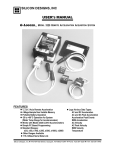
1
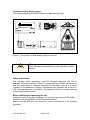
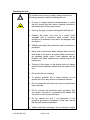
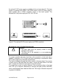
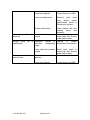
CDPS532M
Continuous Wave Frequency-Doubled
Diode-Pumped Solid-State Laser
User’s Manual
21012687 Rev 001
Page 0 of 28
Contents
Page
Safety Information and Symbols
Classification
Disconnecting from line power
Line power requirement
Laser classification
Location of laser warning signs
Safety instructions
Before initializing and operating the unit
Operating the unit
Safety symbols
Compliance
3
3
3
3
4
4
4
5
6
7
General Information and Specifications
General information
Specifications
7
11
Getting Started
Before initializing and operating the laser
Initial inspection
Storing and shipping
Claims and repackaging
Warranty
Returning shipments to JDS Uniphase
12
12
13
13
13
13
Operating and Maintenance Instructions
External dimensions
Mounting the laser
Using the laser
Laser input/output interface
Analog interface
RS232 interface
Laser controller status display
Disconnecting the umbilical cable
Service and Maintenance
Troubleshooting
14
16
17
19
19
23
26
26
27
27
21012687 Rev 001
Page 1 of 28
List of Illustrations
Page
1
2
3
4
5
6
7
8
9
10
4
8
9
9
14
15
15
16
18
18
Location of laser warning signs
The CDPS532M laser system
Cooling power requirements for the heat sink
Relative humidity vs. temperature
Laser head dimensions
Laser controller dimensions
Umbilical cable
Optional 5V DC power supply
Laser controller connections
5V DC input power connector
List of Tables
1
2
3
4
5
6
7
8
9
10
11
12
13
Laser classification
Safety symbols
Laser specifications
Power supply electrical parameters
5V DC connector pin functionality
Analog interface
Controller calibration constants
RS232 pin funtionality
RS232 protocol
Parameters for the QUERY command
Controller LED functions
Faults indicated via the analog interface
Troubleshooting tips
For sales and service information, contact JDS Uniphase or your local representative
JDS Uniphase Corporation
163 Baypointe Parkway
San Jose, CA 95134
USA
Phone:
800-644-8674 in North America or
408-434-1800
Fax:
408-434-3838
Email:
[email protected]
JDS Uniphase GmbH
Leipziger Str. 4
85386 Eching
Germany
Phone:
(089) 318-880
Fax:
(089) 318-88444
Email:
[email protected]
Please visit our web site at jdsuniphase.com for our world-wide representatives.
21012687 Rev 001
Page 2 of 28
3
6
11
18
19
19
23
23
23
24
26
27
27
Safety Information and Symbols
Classification
The unit consists of an exposed metal chassis that is connected directly to earth
via a power cord and, therefore, is classified as a Class 1 instrument. Class 1
refers to equipment relying on ground protection as a means of shock protection.
The following symbol is used to indicate a protective conductor terminal in the
unit.
Disconnecting from line power
Some of the circuits are powered whenever the unit is connected to the AC
power source (line power). To ensure that the unit is not connected to the line
power, disconnect the power cord from either the power inlet on the unit or from
the AC line-power source (receptacle). The power cord must always be
accessible from one of these points. If the unit is installed in a cabinet, the
operator must be able to disconnect the unit from the line power by the system’s
line-power switch.
Line power requirements
The unit is powered by 5 V/9 A DC supplied to the controller. The maximum
power consumption is 45 W. A DC power supply can be ordered as an option to
operate the unit from a single-phase AC power source. The line requirement is
115 to 230 V at a frequency of 47 to 440 Hz.
Laser classification
The laser specifications are given in Table 1:
Table 1: Laser classification
Parameter
Wavelength
Laser Safety Classification
Output Power
Beam Waist Diameter
21012687 Rev 001
Specification
532 nm
IIIb
10, 20, 50 mW
0.6 mm (± 10%), (1/e2 points)
Page 3 of 28
Locations of laser warning signs
The following drawing shows the locations of laser warning signs.
Figure 1: The location of laser warning signs on the unit.
Warning
Class IIIb lasers are hazardous to eyes and skin if viewed
directly.
Safety Instructions
The following safety instructions must be observed whenever the unit is
operated, serviced or repaired. Failure to comply with any of these instructions or
with any precautions or warnings mentioned in the user’s manual is in direct
violation of the standards of design, manufacture and intended use of the unit.
JDS Uniphase assumes no liability for the customer’s failure to comply with any
of these safety requirements.
Before initializing and operating the unit
Inspect the unit for any sign of damage, and read the user’s manual thoroughly.
Install the unit as specified in the Getting started section.
Ensure that the unit and any devices or cords connected to it are properly
grounded.
21012687 Rev 001
Page 4 of 28
Operating the unit
Warning
To avoid the risk of injury or death, always observe the
following precautions before initializing the unit:
21012687 Rev 001
•
If using a voltage-reducing autotransformer to power
the unit, ensure that the common terminal connects to
the earthed pole of the power source.
•
Use only the type of power cord supplied with the unit.
•
Connect the power cord only to a power outlet
equipped with a protective earth contact. Never
connect to an extension cord that is not equipped with
this feature.
•
Willfully interrupting the protective earth connection is
prohibited.
•
Never look into the laser beam emitted either from the
laser head or the end of an optical cable connected to
an operating optical output. Laser radiation can be
invisible, and direct exposure can severely injure the
human eye.
•
Turning off the power to the device does not always
block the entire radiation emitted from the output of the
unit.
•
Do not use the unit outdoors.
•
To prevent potential fire or shock hazard, do not
expose the unit to any source of excessive moisture.
•
Do not operate the unit when its covers or panels have
been removed.
•
Do not interrupt the protective earth grounding. Any
such action can lead to a potential shock hazard that
can result in serious personal injury.
•
Do not operate the unit if an interruption to the
protective grounding is suspected. In this case, ensure
that the unit remains inoperative.
•
Unless absolutely necessary, do not attempt to adjust
Page 5 of 28
or perform any maintenance or repair procedure when
the unit is opened and connected to a power source.
•
Repairs are to be carried out only by a qualified
professional.
•
Do not attempt any adjustment, maintenance or repair
procedure to the unit’s internal mechanism if immediate
first aid is not accessible.
•
Disconnect the power cord from the unit before adding
or removing any components.
•
Operating the unit in the presence of flammable gases
or fumes is extremely hazardous.
•
Do not perform any operating or maintenance
procedure that is not described in the user’s manual.
•
Some of the unit’s capacitors can be charged even
when the unit is not connected to the power source.
Safety symbols
The following symbols and messages can be marked on the unit (Table 2).
Observe all safety instructions that are associated with a symbol.
Table 2: Safety symbols
Symbol
Description
Laser safety. See the user’s manual for instructions on
handling and operating the unit safely
!
See the user’s manual for instructions on handling and
operating the unit safely.
Frame or chassis terminal for electrical grounding within
the unit.
Protective conductor terminal for electrical grounding to
the earth.
21012687 Rev 001
Page 6 of 28
WARNING
CAUTION
The procedure can result in serious injury of loss of life if
not carried out in proper compliance with all safety
instructions. Ensure that all conditions necessary for safe
handling and operation are met before proceeding.
The procedure can result in serious damage to or
destruction of the unit if not carried out in compliance with
all instructions for proper use. Ensure that all conditions
necessary for safe handling and operation are met before
proceeding.
Compliance
The unit has been designed and tested to comply with the following standards:
Electromagnetic Emissions (EN 50081-1) tested to standard CISPR 11:1999 +
A1.
Electromagnetic Immunity (EN 61000-6-2) tested to standard EN 61000-4-2 and
EN 61000-4-3.
Safety evaluation tested to standard UL 3101 and EN 61010-1.
The CDPS532M laser system is an OEM version of a JDS Uniphase diodepumped solid-state laser and as such only intended for integration into other
equipment. These lasers do not comply with CDRH or EN 60825-1. The
customer is responsible for CDRH or 60825-1 compliance of the system
incorporating the CDPS532M laser system.
General information and specifications
General information
The CDPS532M is a continuous-wave, frequency-doubled diode-pumped solidstate laser operating at a wavelength of 532 nm. The laser can provide an output
power of 10 - 50 mW. The CDPS532M provides a very stable and low noise laser
beam in a compact package, especially designed for original equipment
manufacturing and system integration. The low noise operation is achieved via
single-longitudinal mode operation.
The laser (Figure 2) consists of a laser head, a controller and an umbilical cable
connecting the head and the controller. To prevent electrostatic damage to the
pump laser diode mounted in the laser head the controller and the laser head
have to stay connected at all times. The laser is powered by supplying 5 V DC to
the controller by either an optional DC power supply or by a customer provided
DC power supply.
21012687 Rev 001
Page 7 of 28
Figure 2: The CDPS532M laser system.
In the laser head lasing is achieved in a two mirror linear cavity containing the
Nd:Vanadate (Nd:YVO4) crystal and the intra-cavity frequency doubling crystal. A
KTP crystal is used to convert the fundamental 1064 nm radiation into the 532
nm green output beam. The pump power for the Vanadate crystal is provided via
a 808 nm pump laser diode outside the laser cavity. The pump diode wavelength
is matched to the Vanadate absorption line. All these components are mounted
in a metal structure for mechanical stability. The laser beam exhibits a very good
mode quality close to diffraction limit. The output beam from the cavity is imaged
with a telescope, resulting in a low divergence beam with a divergence of < 1.2
mrad.
The whole cavity is temperature stabilized for long term stability using a
thermoelectric cooler. The heat dissipation takes place through the base plate of
the laser head. For proper operation the laser head has to be mounted on a heat
sink. The base plate temperature has to be kept below 45°C by the heat sink.
21012687 Rev 001
Page 8 of 28
Heat Load [W]
15
10
5
0
10
20
30
40
50
Base Plate Temperature [°C]
Figure 3: Cooling power requirement for the heat sink.
Relative Humidity Vs. Temperature
110%
laser set at 15
C
100%
20 C
25 C
30 C
40 C
35 C
90%
80%
Relative Humidity (%)
Condensing region
70%
60%
50%
40%
30%
Non-Condensing region
20%
10%
0%
0
5
10
15
20
25
30
35
40
45
50
55
60
65
70
75
80
Temperature (C)
Figure 4: Relative humidity vs. temperature for a non-condensing
environment.
21012687 Rev 001
Page 9 of 28
The laser has to be operated in a non-condensing environment. The
temperature/relative humidity condition can be estimated by using the graph
above (Figure 4).
The controller drives the pump laser diode, the thermoelectric cooler and uses a
photo-diode and thermistor signal for feedback loops. After warm-up the
controller switches to constant power operation. A photo diode signal is used to
keep the output power of the laser stable via adjustment of the pump laser diode
power. This is done via controlling the pump diode driving current.
To operate the laser a 5 V DC supply has to be connected to the controller. The
laser system can be controlled and monitored either via a RS232 interface or via
an analog interface.
21012687 Rev 001
Page 10 of 28
Specifications
The following table summarizes the specifications for the CDPS532M.
Table 3: Laser specifications
Optical
Wavelength [nm]
Output Power [mW]
CDPS532M-010
CDPS532M-020
CDPS532M-050
Power Stability (2 hour, 25 ± 3 °C) [%]
Mode Quality M2
Beam Waist Diameter (1/e2 point) [mm]
Beam Divergence (full angle) [mrad]
Polarization Ratio (E-vector is vertical)
Noise (rms, 20 Hz – 2 MHz) [%]
Ellipticity [%]
Pointing Stability (after 2 hour warm-up, 25 ± 3 °C) [µrad]
Static Alignment
Beam position [mm]
Beam angle [mrad]
Environmental
Base Plate Temperature [°C]
Operating
Non-operating
Shock (11 msec duration) [g]
Operating
Non-operating
Vibration (sinusoidal, 5 – 500 Hz) [g]
Operating
Non-operating
Heat Sink Requirements
Surface Flatness [µm]
Torque Specification [Nm]
Sound Power Level
Ultrasonic Pressure Level
21012687 Rev 001
Page 11 of 28
532 ± 1
10
20
50
<1.0
<1.2
0.6 (± 10%)
<1.2
>100:1
<0.5
<10
± 30
± 0.25
± 1.0
10 - 45
0 - 60
1
25
0.3
2
25
0.5
N/A
N/A
Getting started
Before initializing and operating the laser
• Check that he unit was shipped with all parts
• Check that there is no obvious damage to the unit.
• Read the user’s manual thoroughly, and become familiar with all safety
symbols and instructions to ensure that the unit is operated and maintained
safely
Initial Inspection
Warning
• To avoid electrical shock, do not initialize or operate
the unit if it bears any sign of damage to any portion of
its exterior surface, such as the outer cover or panel.
!
•
Never look into the laser beam emitted either from the
laser head or the end of an optical cable connected to
an operating optical output. Laser radiation can be
invisible, and direct exposure can severely injure the
human eye.
•
Do not use the unit outdoors.
•
To prevent potential fire or shock hazards, do not
expose the unit to any source of excessive moisture.
Caution
• Always have the laser head and laser controller
connected before applying power to the unit.
Check that the unit and contents are complete:
1. Wear an anti-static wrist strap and work in an electrostatic discharge (ESD)
controlled area.
2. Inspect the shipping container for any indication of excessive shock to the
contents, and inspect the contents to ensure that the shipment is complete.
3. Inspect the unit for structural damage that can have occurred during
shipment.
4. Ensure that the laser head is connected to the controller.
5. Keep the packaging.
Immediately inform JDS Uniphase and, if necessary, the carrier if the contents of
the shipment are incomplete, if the unit or any of its components are damaged or
defective, or if the unit does not pass the initial inspection.
21012687 Rev 001
Page 12 of 28
!
Caution
• For environmental operating conditions see General
information and Mounting the laser
Storing and Shipping
To maintain optimum operating reliability, do not store the unit in locations where
the temperature falls below 0°C or rises above 60°C. Avoid any environmental
condition that can result in internal condensation. Ensure that these temperature
and humidity requirements can also be met whenever the unit is shipped.
Claims and Repackaging
Immediately inform JDS Uniphase and, if necessary, the carrier, about a claim. In
the event of carrier responsibility, JDS Uniphase will allow for the repair or
replacement of the unit while the claim against the carrier is being processed.
Removal of either the laser head cover or controller cover voids the warranty.
Warranty
JDS Uniphase diode-pumped solid-state lasers are warranted to be free of
defects in material and workmanship for twelve months from date of shipment or
5,000 h, whichever occurs first.
Returning Shipments to JDS Uniphase
JDS Uniphase only accepts returns for which an approved Return Material
Authorization (RMA) has been issued by JDS Uniphase. This number must be
obtained prior to shipping any material back to JDS Uniphase. The owner’s name
and address, the model number and full serial number of the unit, the RMA
number, and an itemized statement of claimed defects must be included with the
return material.
Ship return material in the original shipping container and packing material. If
these are not available, typical packaging guidelines are as follows:
• Wear an anti-static wrist strap and work in an ESD controlled area.
• Cover the front panel, if applicable, with lens cleaning tissue taped to the front
panel.
• Wrap the unit in anti-static packaging. Use anti-static connector covers, as
applicable.
• Pack the unit in a reliable shipping container.
• Use enough shock-absorbing material (10 to 15 cm on all sides) to cushion
the unit and prevent it from moving inside the container. Anti-static foam
material is the best material.
• Seal the shipping container securely.
• Clearly mark FRAGILE on the outside of the container.
• Always provide the model and serial number of the unit and the RMA number
on any accompanying documentation.
• Ship the unit only to the address given at the beginning of this document.
21012687 Rev 001
Page 13 of 28
Operating and Maintenance Instructions
External Dimensions
The laser head is shown in figure 5 (dimensions are in mm):
21012687 Rev 001
Page 14 of 28
The laser controller is shown in figure 6 (dimensions are in mm):
77.34
7.62
43.69
59.95
140.64
91.92
51.94
4X
2.79
4X
3.66
AIR FLOW
5.59
126.38
152.40
100
61.47
99.70
LASER HEAD INTERFACE
15 PIN D-SUB FEMALE CONNECTOR
23.88
Laser head and controller are connected via the umbilical cable with a 15-pin Dsub connector at each end (figure 7). The umbilical cable is installed at the
factory and the warranty is void if the cable is disconnected on either the laser
head or controller side. The standard length of the umbilical cable is 765 mm.
Figure 7: The umbilical cable connects laser head and controller.
21012687 Rev 001
Page 15 of 28
An optional 5V DC power supply is available for the unit (see figure 8). The laser
system is compliant with CDRH, if the CDRH version of the 5V power supply is
used together with a CDRH compliant version of the laser system. The
dimensions of the power supply are 164 x 82 x 55 mm.
Figure 8: The optional 5V DC power supply (not CDRH compliant)
Mounting the Laser (Cooling Requirements)
Caution
• The laser head must be properly cooled to avoid
!
damage to the system.
• The laser has to be operated in a non-condensing
environment.
For proper operation the laser head has to be mounted to a heat sink that is
capable to dissipate 10 W of heat load while maintaining a temperature below
45°C (refer to figure 2 for heat sink requirements).
The heat is dissipated through the bottom surface of the laser head. Four screws
in each corner of the laser head are used to mount the laser head to the heat
sink. A torque of 0.5 Nm has to be used to mount the screws.
For proper heat contact a surface flatness of the mounting surface of the heat
sink of 25 µm is required. Alternatively a thermal pad (part number 4906-002)
can be used between laser head and heat sink. The usage of thermal compound
or grease is forbidden.
21012687 Rev 001
Page 16 of 28
Using the Laser
Warning
• Never look into the laser beam emitted either from the
laser head or the end of an optical cable connected to
an operating optical output. Laser radiation can be
invisible, and direct exposure can severely injure the
human eye.
•
Never leave the laser on, unattended.
•
Always have the power supply cover, the controller
cover and the laser head cover in place when the laser
is connected to line power.
•
When the laser is on and the output beam is not being
terminated in an experiment or optical system, block
the beam.
•
Set up experiments so that the laser beam is not at eye
level.
To use the laser
!
Caution
• The laser controller has been factory adjusted to
operate the CDSP532S laser. Do not attempt to
operate the laser with any other equipment.
• To avoid damage to the laser, or for safety reasons, do
not use the laser system in any manner not described
in this manual
Mount the laser head to a heat sink.
The power supply, controller and laser head must be installed in an equipment
enclosure by the end user to comply with all electrical safety regulations.
A 5V DC power supply is needed to operate the laser. The 5V DC can be
supplied either by an optional JDS Uniphase power supply or by a customer
supplied unit. The 5V return line of the power supply must be connected to the
earth ground of the power supply or the controller and the laser head must be
grounded to an earth grounded mounting plate to satisfy all electrical safety
requirements. The maximum power of the power supply has to be limited to
150W. The 5V power supply has to comply with the following specifications:
21012687 Rev 001
Page 17 of 28
Table 4: Power supply electrical parameters
Parameter
Specification
Input voltage
5.0 ± 0.2 Vdc
Line regulation
± 0.1%
Noise and ripple
1% peak-to-peak
Current
9A
Power
45 W
The power is supplied to the controller via a 4 pin AMP 1-350944-0 connector
(see figure 9).
INTERLOC K, 25 PIN D-SUB FEMALE C ONNEC TO R
INPUT SUPPLY C ONNEC TO R
R S232, 9 PIN D-SUB FEM ALE C ONNEC TO R
LED
Figure 9: Laser controller connections
The 5V DC input power connector is shown in figure 10, and the pin functionality
is listed in the following table.
Figure 10: 5V DC input power connector.
21012687 Rev 001
Page 18 of 28
Table 5: 5V DC Connector Pin Functionality
Pin #
Functionality
1
Ground
2
Ground
3
+ 5V
4
+ 5V
!
Caution
• Always have the laser head and laser controller
connected before applying power.
• Do not connect the 5V power supply to the controller
while the 5V DC is present. Apply and remove the 5V
only after switching of the 5V DC power.
The laser will only turn on if:
The interlock chain (pin# 12 and 24, 25-pin D-sub) is shorted and the unit power
and Laser emission on/off (pin# 1 and 14, 25 pin D-sub) are driven to TTL low.
Connect the 5V power supply and apply power. The laser is now active.
Laser Input/Output Interface
The laser can be monitored and controlled via the RS232 and analog interface.
Analog Interface
The functions of the analog interface are summarized in the following table.
Table 6: The Analog Laser Interface (25-pin D-sub connector)
Function
Pin
Comments
Numbers
Digital Input. This pin must be at TTL low level
Unit Power on/off
Pin 1
in order to enable unit power up and for laser
emission to occur.
Digital/Analog
Pin 2
ground
Digital Input. This input selects the type of
Feedback mode
Pin 3
feedback that will be implemented during laser
emission. If left unconnected, this pin will be
pulled to +5V by an internal 4.75K ohm pull-up
resistor, and the feedback mode will be “light”
mode. That is, laser output power will be held
constant. If this pin is shorted to Digital/Analog
ground, or driven to TTL low level by external
hardware, the feedback mode will be constant
21012687 Rev 001
Page 19 of 28
“current” mode. That is, the current flowing
through the laser diode will be held constant.
The light feedback mode may be a two-stage
process depending on operating conditions.
The unit will remain in constant current mode
until the TEC’s have locked to the set
temperature. After a short delay, the unit will
switch to “light” feedback mode.
Active state “0” = current mode
“1” = light mode
Laser diode current
status ok/bad
Internal fault ok/bad
Pin 5
Pin 6
Digital Output. If the laser diode current
exceeds 95% of the diode current limit value,
then this output is driven to 0V, TTL logic low
level. If the laser diode current is below 95%
of the current limit value, then this output is
driven to 5V, TTL logic high level. This signal
is useful to indicate that a diode is near its end
of life. As the diode ages, more current is
required to achieve a certain laser output
power level.
Active state “0” = bad
“1” = ok
Digital Output. Under normal conditions, this
output is at TTL logic high. This output is
driven to 0V, TTL logic low level under the
following condition:
1. Interlock open
2. Diode current exceeded internal limit.
3. TEC Shutdown.
Diode cavity
temperature exceeds 45 °C. This error
is latched.
Latched errors require that the laser power
supply is cycled off and on.
Interlock fault
ok/bad
21012687 Rev 001
Pin 7
Active state “0” = bad
“1” = OK
Digital Output. If the interlock chain is broken,
then this output signal is driven to 5V, TTL
logic high level. When the interlock chain is
unbroken, this output signal is driven to 0V,
TTL logic low level. The laser output is latched
Page 20 of 28
off (when the user interface jumper is not used)
in the event the interlock chain is broken during
operation. The unit power must be cycled off
and on; or a LON command can be sent
through the RS232 interface to re-establish
lasing.
Set laser power
Pin 8
Digital/Analog
ground
Pin 9
+ 5V out
Pin 10
Laser power
monitor
Pin 11
Interlock chain in
Pin 12
Shorting link
(signal)
Pin 13
Laser emission
on/off
Pin 14
Active state “0” = OK
“1” = bad
Analog Input. This proportional analog control
input may be used to set the laser power
directly.
The input voltage range is 0 to 4.095V.
Analog Output. This proportional analogue
output gives a real time value proportional to
the instantaneous laser output power. This
signal is derived from analog electronics
directly, but is also sampled by the on board
uController to 10 bit accuracy.
Analog Input. This input must be shorted to the
interlock chain “out” pin (Pin 24) for the laser
diode to be able to be turned on. Both pins
must be provided to the customer to connect
any safety switches located in user equipment.
Analog Input. The user-connector-present link
pins 13 and 25 are to be shorted together to
indicate that the unit is to be controlled through
the user interface partially or wholly. If the link
is not detected, then the unit cannot be
controlled via the P1 interface.
Digital Input. This input controls laser emission.
If left unconnected, this pin will be pulled to
+5V by an internal 10K ohm pull-up resistor,
and laser emission will be disabled. If this pin
is shorted to Digital/Analog ground, or driven to
TTL low level by external hardware, then laser
emission may occur, subject to valid operation
conditions (e.g. interlock ok, no faults, actual
current/power demand signal present.
There is approximately a 5-second delay
between laser emission request and actual
21012687 Rev 001
Page 21 of 28
laser emission. (CDRH)
Laser emission on
(status)
Laser power status
ok/bad
Pin 16
Pin 18
Set laser current
Pin 19
Analog laser power
enable
Pin 22
Active state “0”, laser emission is ON.
Digital Output. This pin is set to 5V when the
laser is enabled. This setting includes the
short waiting time before the diode actually
does turn on when emission is enabled by pin
14. It is at ground at all other times.
Active state “0” = OFF
“1” = ON
Digital Output. If the laser output power is not
within ± 5% of the expected value, then this
output signal is driven to 0V, TTL logic low
level. IF the laser output power is within
specifications, then this output signal is driven
to 5V, TTL logic high level.
Active state “0” = bad
“1” = OK
Analog Input. This proportional analog control
input may be used to set the laser current
directly.
The input voltage range is 0 to 3V.
Digital Input. This input must be raised to +5V
in order for the voltages on pin # 8 to be
accepted as the laser power control settings.
Until this pin is activated, the unit will run at a
power level set by its internally stored values
or controlled through the RS-232 interface.
Laser diode current
monitor
Pin 23
Interlock chain out
Pin 24
Active state “1” = analog laser power enable
Analog Output. This proportional analog output
gives a real time value proportional to the
instantaneous laser diode current. This signal
is derived from analog electronics directly, is
also sampled by the controller’s 12-bit ADC.
Analog Input. See pin #12.
Shorting link (0V
logic)
Pin 25
Analog Input, See pin #13.
The analog interface allows a couple of control and monitor functions that require
a DC voltage proportional to a certain parameter. The controller internal
calibration constants are given in the following table.
Table 7: Controller Calibration Constants
21012687 Rev 001
Page 22 of 28
Pin #
8
Function
Set laser power
11
Laser power monitor
19
23
Set laser current
Laser diode current
monitor
50 mW
20 mW
10 mW
50 mW
20 mW
10 mW
Calibration constant
0.0683 V/mW
0.164 V/mW
0.274 V/mW
0.0683 V/mW
0.164 V/mW
0.274 V/mW
0.5 A/V
0.5 V/A
RS232 Interface
The laser can be controlled and monitored via a RS232 interface (9 pin D-sub
connector). The following connector pins are used for the interface. The interlock
loop on the analog interface (25 pin D-sub connector, pin# 12 and 24) has to be
closed. For proper operation of the laser we recommend that all other
connections to the analog interface to be disconnected.
Table 8: RS232 Pin Functionality
Pin #
Functionality
2
TxD
3
Rxd
5
Ground, 0V
The following table describes the RS232 protocol for the CDPS532M laser.
Table 9: RS232 Protocol
Command
Scaling
Range
Acknowledgement
SLC nnnn<cr> Diode current • 2000
0 – 1.5 A
(slc) nnnn#<cr>
Description SLC nnnn<cr>
Sets pump diode current and changes the control mode to current mode.
CSP nnnn<cr> Diode current • 2000
0 – 1.5 A
(csp) nnnn#<cr>
Description CSP nnnn<cr>
Sets pump diode current without changing the laser control mode.
(slp) nnnn#
Output power / N x 4095
0 – 10 mW if succeeds
N = 15 @ 10 mW
0 – 20 mW
N = 25 @ 20 mW
0 – 50 mW
N = 60 @ 50 mW
Description SLP nnnn<cr>
Sets laser output power and changes the control mode to power mode.
SLP nnnn<cr>
PSP nnnn<cr>
21012687 Rev 001
Output power / N x 4095
Page 23 of 28
(psp) nnnn#
0 – 10 mW if succeeds
N = 15 @ 10 mW
0 – 20 mW
N = 25 @ 20 mW
0 – 50 mW
N = 60 @ 50 mW
Description PSP nnnn<cr>
Sets laser output power without changing the laser control mode.
LOFF<cr>
Description LOFF<cr>
Turns laser off.
(loff)#
ON_C<cr>
Description ON_C<cr>
Turns laser on in current mode.
(lonc)#
ON_L<cr>
Description ON_L<cr>
Turns laser on in light mode.
(lonl)#
QUERY<cr>
See table below
See table below
Description QUERY<cr>
The controller returns 13 items, a semi-colon separates each item. The analog
values (nnnn) range from 0 – 4095 and the digital values (ddd) from 0 – 255.
Items 10 to 13 (x) are for internal use only.
VER<cr>
Typical
version
follows this format:
Ver 3.1Build 25 1019-01#<cr>
Description VER<cr>
Returns the version of the firmware.
OT?<cr>
M x 10,000 + m =
minutes, s = seconds
m = minutes, s = seconds
Description OT?<cr>
Returns the laser’s on-time in minutes.
(on time) M;m:s#<cr>
(on time) m:s#<cr>
The following table lists the parameters for the RS 232 QUERY command listed
above.
Table 10: The Parameters for the QUERY Command
Acknowledgement
(query) nnnn;nnnn;nnnn;nnnn;nnnn;nnnn;ddd;ddd;ddd;x;x;x;x#
Item #
Scaling
Description
1
N/A
N/A
21012687 Rev 001
Page 24 of 28
2
3
4
5
6
7
nnnn / 100
nnnn x N / 4095
N = 15 @ 10 mW
N = 25 @ 20 mW
N = 60 @ 50 mW
nnnn / 2000
N/A
(2250 – nnnn) / 500
Laser cavity temperature [°C]
Laser output power [mW]
Pump diode current [A]
N/A
Laser cavity TEC drive current [A]
Digital Input
Bit #
0
Unit power on/off
1
Laser emission on/off
2
Feedback mode
3
Analog laser power enable
4
Shorting link (signal)
5
Interlock chain in
6
TEC shutdown
1=normal, 0=shutdown
7
N/A
Digital Output
Bit #
0
Internal fault ok/bad
1
Light/current mode
1=light, 0=current
2
Crowbar
1=on, 0=off
3
LED: laser emission
1=off, 0=on
4
LED: laser in specification
1=off, 0=on
5
LED: thermal fault
1=off, 0=on
6
LED: internal fault
1=off, 0=on
7
Interlock fault ok/bad
Digital Output
Bit #
0
N/A
1
N/A
2
N/A
3
N/A
4
Laser diode current status
ok/bad
5
Laser power status ok/bad
6
N/A
8
9
21012687 Rev 001
Page 25 of 28
7
N/A
N/A
N/A
N/A
10
11
12
13
N/A
Laser controller status display
The laser controller status is displayed with five LEDs. The functions of these
LEDs are described in the following table.
Table 11: Controller LED Functions
LED color
Description
Yellow
Laser emission
Green
Laser in specifications
Red
Thermal fault
Red
Internal fault
Green
Unit power
Comments
Illuminated whenever diode emission is
enabled. Lights five seconds before laser
emission.
Illuminated when laser is operating within
±5% of the set output power. LED is
blinking if laser power fluctuates by more
than ±5%.
Illuminated when TEC control loop
cannot maintain its temperature set
point.
Note: This LED may be illuminated
when power is first applied to the laser
controller. It should go off once
temperature reaches set-point.
Illuminated when
1. Interlock is open.
2. Diode current exceeded safe
operating limit. This error is latched;
power supply must be cycled off and
on.
3. Cavity temperature exceeds 45 °C.
This error is latched; power supply
must be cycled off and on.
Illuminated whenever DC voltage is
supplied to controller.
Disconnecting the Umbilical cable between Head and Controller
The laser is shipped with the umbilical cable installed at the factory. Laser heads
and controllers are NOT interchangeable, so disconnecting the unit is not
recommended. The warranty is void if the umbilical cable is disconnected without
clearance from JDS Uniphase.
21012687 Rev 001
Page 26 of 28
!
Caution
• Only work in an ESD controlled area and wear an antistatic wrist strap.
If absolutely necessary, use the following instructions to disconnect the umbilical
cable:
Wear an anti-static wrist strap and work in an ESD controlled area.
Disconnect the cable from either the laser head or the controller. For the laser
head, immediately reconnect a shorting plug to the D-sub connector or
immediately shorten the pins of the D-sub connector using conductive foam, to
prevent ESD damage to the pump laser diode inside the laser head.
Service and Maintenance
There are no user serviceable parts required for the laser system, nor is there
any routine maintenance that needs to be performed on the laser system.
Troubleshooting
Laser system faults can be checked via the 25-pin D-sub connector of the analog
interface.
Table 12: Faults indicated via the analog interface
Pin Number
Fault
#5
Laser diode current status
#6
Internal fault
#7
Interlock fault
#18
Laser output power status
Table 13: Troubleshooting tips
Problem
Probable Cause(s)
5V DC is not supplied
Laser does not turn on
(no light emitted from
Interlock loop (analog
aperture)
interface, pins #12 and
24) open
Low output power
21012687 Rev 001
Pins #1 and #14 (analog
interface)
are
not
grounded or at TTL logic
low
Pump laser diode current
at maximum
Page 27 of 28
Solution
Turn on 5V DC supply
Remove
interlock
condition, close interlock
loop
Ground pins #1 and #14
or drive to TTL logic low
Check pins #5 or #23 , if
at
maximum
contact
factory for RMA
Laser miss-aligned
Contact factory for RMA
Laser mounting stress
Remount laser head
using
proper
torque
specifications. Mount to
flat heat sink surface.
Clean window with lens
cleaning
tissue
and
methanol.
Laser turns off after Laser head not properly Mount laser head to
warm-up
cooled
proper heat sink. Ensure
proper heat contact.
in
proper
Optical noise out of Operation outside of Operate
specification
specified
temperature temperature environment
range
Output window dirty
Laser head not properly Mount laser head to
proper heat sink. Ensure
cooled
proper heat contact.
Laser turns on, but no Obstruction
in
laser Remove obstruction
output beam
aperture
Laser miss-aligned
21012687 Rev 001
Page 28 of 28
Contact factory for RMA