1
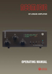
ALPHA 99
HF LINEAR AMPLIFIER
OPERATING MANUAL
© 2006 Alpha Radio Products, Inc
All rights reserved
Specifications subject to change without notice
ALPHA 99 OPERATING MANUAL
www.alpharadioproducts.com
ALPHA 99 OPERATING MANUAL
www.alpharadioproducts.com
Table of Contents
1 Introduction
7
1.1 General Description
7
1.2 Amplifier Capabilities
8
1.3 Shipping Information
8
1.4 Safety Information – Installation and Operation
1.5 Owner Assistance
9
2 Quick Start Information
8
11
2.1 Overview
11
2.2 Station Engineering Considerations - Checklist
2.3 Preparation
11
2.4 Unpacking
12
2.5 Operation
12
11
3 Station Engineering Considerations
13
3.1 Overview
13
3.2 AC Power Source
13
3.3 Air Flow
13
3.4 Antennas
14
3.5 Coax and Connectors
3.6 RF Safety
15
15
4 Unpacking & Preparation
17
4.1 Unpacking
17
4.2 Installing the Power Transformer
17
4.2.1 Install the Power Transformer
18
4.2.2 Connecting the Transformer Power Plugs
20
4.2.3 Power Cord Connections
21
4.2.4 Important Information About Operation from 90-130V AC
4.3 AC Primary Connections
22
ALPHA 99 OPERATING MANUAL
www.alpharadioproducts.com
21
4.4 Complete the Transformer Installation
4.4.1 RF Grounding
25
4.4.2 Replacing the Amplifier Cover
25
4.4.3 Blower Preparation
25
4.5 Amplifier/Station Interconnections
25
4.5.1 Coaxial Cable Types & Connectors
4.5.2 T/R Control Cable
26
4.5.3 ALC 26
5 Theory of Operation
29
5.1 Theory of Operation - Overview
5.2 Tubes
29
5.3 Output Tank Circuit 29
5.4 Tube Deck
30
5.5 Mains Board
30
5.6 High Voltage Board 30
5.7 Control Board 31
5.9 Output Wattmeter Board
31
5.10 Center Partition Board
32
29
25
25
6 Operation & Maintenance
33
6.1 Before Operating Your Alpha 99
33
6.1.1 Setting Input Drive
33
6.1.2 Dealing with Faults
33
6.1.3 High SWR Considerations
34
6.1.4 Operating at Less Than 1.5 kW Requires Retuning
6.1.5 Lightning Protection
35
6.1.6 Operating in Bypass Mode
35
6.1.7 Never Use Transceiver Automatic Antenna Tuner
6.2 Transceiver Connections
35
6.3 Initial Setup & Tuning
36
6.3.1 Control Functions
36
6.3.2 Tune-Up
37
6.3.3 Grid Current Information
37
ALPHA 99 OPERATING MANUAL
www.alpharadioproducts.com
34
35
6.3.4 ALC
38
6.3.5 Turning On The Amplifier
38
6.3.6 Tuning the Amplifier
39
6.4 Normal Use
41
6.4.1 Tubes
41
6.4.2 Interlocks
42
6.4.3 Fuses
42
6.4.4 Plate Overcurrent Relay
43
6.4.5 Idling Plate Current and Electronic Bias Control (Ebs)
6.4.6 RF and Mistuning Protection
43
6.5 Standard Maintenance Tasks
43
7 Troubleshooting Hints
7.1 Normal Troubleshooting
8 Glossary
45
49
ALPHA 99 OPERATING MANUAL
www.alpharadioproducts.com
45
43
ALPHA 99 OPERATING MANUAL
www.alpharadioproducts.com
1 Introduction
1.1 General Description
Congratulations on your purchase of a professional quality Alpha 99 amplifier! With proper
installation and care, you can expect to enjoy your Amateur Radio hobby with this amplifier
improving your signal for many years to come. Please study this manual carefully before
operating your amplifier for the first time.
The Alpha 99 is a self-contained manual tune HF linear power amplifier capable of continuous
operation at 1500 W peak power output on SSB, keyed CW, SSTV, RTTY, digital modes or FM, with
no time limit.
Other Alpha products available to enhance your use and enjoyment of the 99 amplifier include:
• Alpha 2100 full 1500-watt rated 50-ohm dummy loads and
• Alpha 4500 series SWR meters / Wattmeter
See our web site at www.alpharadioproducts.com or call 303-473-9232 for further information.
ALPHA 99 OPERATING MANUAL
www.alpharadioproducts.com
1.2 Amplifier Capabilities
CAUTION:
It is extremely important to thoroughly review the Installation and Operation
sections of this manual before attempting to use the Alpha 99. Failure to do so
could result in serious damage not covered under warranty.
• Continuous RF Output. The 99 is capable of 1.5 kW continuous RF output on all commonly used
modes and on any authorized amateur frequency from 1.8 to 29.7 MHz.
• Compatibility with popular amateur transceivers and exciters. The 99 requires approximately
50-65 W peak RF drive for 1.5 kW output.
• Capable of full CW break-in, QSK and all digital modes when used with any appropriate
transceiver.
• Protective functions are built in. The control system incorporates protective functions that
minimize the probability of accidental damage to the amplifier or its power tubes. In most cases,
when one of the protective functions is “tripped,” the amplifier will go to Standby.
1.3 Shipping Information
The Alpha 99 amplifier ships in two heavy-duty cardboard cartons. One carton holds the power
transformer and weighs 43 lb (20 kg) and the second carton contains the amplifier and weighs 38 lb. (17
kg).
Alpha recommends that you retain the pallet and the cartons after installation in the unlikely
situation that you need to ship the unit later. Contact Alpha at 303.473.9232 for shipping advice
and assistance.
1.4 Safety Information – Installation and Operation
• Make sure the Alpha 99 is located where there is good air circulation all around and on top
of the cabinet. The unit may become hot during operation.
• The Alpha 99 weighs approximately 68 pounds when the transformer is installed. Use
proper lifting techniques and two people when moving the amplifier.
• The Alpha 99 is designed to meet international safety standards and FCC regulations.
ALPHA 99 OPERATING MANUAL
www.alpharadioproducts.com
However, one should always remember that the equipment works with high voltages that
can be LETHAL!
This operating manual holds information, cautions and warnings that must be followed to ensure
safe installation and operation. Read Chapter 1 before attempting to unpack or operate the
Alpha 99 amplifier.
Warnings: What Not to Do
• Never open the amplifier case without unplugging the unit from the wall outlet.
• Never stick objects into holes in the case.
• Never touch an antenna during transmission.
• Never attempt to turn on the amplifier without the cover securely in place (all
attachment screws reinserted).
• Never turn the amplifier back on after a hard fault without waiting at least 20
seconds.
• Always resist the temptation to immediately hit the ON button after the
amplifier faults to power off.
• Never allow liquids to enter the amplifier through the cover holes.
Warnings posted in this manual should be read and thoroughly understood
by users. Failure to perform procedures properly may result in amplifier
damage, fire hazard, or electric shock.
1.5 Owner Assistance
Technical Assistance from Alpha Radio Products is available from several sources.
• The Alpha Radio Products web site is www.alpharadioproducts.com. Click on Support and
follow the instructions. Many typical problems and their solutions are listed on this site. On
this site you can get the following assistance:
•
•
•
•
•
•
•
Technical Support
Repair Information
Software Downloads
Manuals
Tech Tips
Legacy Equipment Information
FAQs
ALPHA 99 OPERATING MANUAL
www.alpharadioproducts.com
10
• You can e-mail us for customer support at [email protected] or you can send
your request by fax to 303.473.9660.
ALPHA 99 OPERATING MANUAL
www.alpharadioproducts.com
11
2 Quick Start Information
2.1 Overview
This section explains in brief the items you need to consider when setting up your Alpha 99
amplifier.
If you already have a well-designed shack and have used an amplifier before, please review the
items below to make sure you have considered all the critical items for proper installation and
operation.
If you are using an amplifier for the first time, please skip this section and go to sections 3, 4, and
5 for a more detailed explanation of how to set up your shack for maximum safety and operating
enjoyment.
If you have installation questions, do not hesitate to contact Customer Support. We much prefer
to address questions prior to power up.
2.2 Station Engineering Considerations - Checklist
Make sure you have properly addressed the following concerns (Section 2.3 below) before
installation of your Alpha 99 amplifier. If you are unsure of any of these items, please read the
noted sections carefully.
2.3 Preparation
__
__
__
__
220V AC Power in shack? (Section 3.2)
Amplifier placed with proper airflow? (Section 3.3)
Antenna ready for 1,500W? (Section 3.4)
Adequate RF cabling? (Section 3.5)
ALPHA 99 OPERATING MANUAL
www.alpharadioproducts.com
12
2.4 Unpacking
__
__
__
__
__
__
Unit Checked for Damage?
Transformer Installed? (Section 4.2.1, 4.2.2)
Power Cord Connector Attached? (Section 4.2.3)
AC Primary Voltage Set? (Section 4.3)
Amplifier Grounded Properly? (Section 4.4.1)
Amplifier Cover Replaced and Secured? (Section 4.4.2)
2.5 Operation
__ All Exciter Interconnections Set? (Section 6.2)
__ Exciter Drive Correctly Set? (Section 6.1.1)
__ Amplifier Tuned to Antenna System? (Section 6.3.6)
ALPHA 99 OPERATING MANUAL
www.alpharadioproducts.com
13
3 Station Engineering Considerations
3.1 Overview
The Alpha 99 is capable of dramatically improving the performance of your amateur station. It
is important that you observe good engineering practices to achieve all the benefits of such a
station in a safe and reliable manner. This section provides a few hints for important operational
considerations, but it is recommended that the user also consult a good source of general
information such as “The Radio Amateur’s Handbook” by the ARRL, especially if this is the first
high-power amplifier you have used.
3.2 AC Power Source
This amplifier runs best when powered by a 200V - 240V AC circuit. If you do not have a 220V
AC outlet in your shack, you will need to get a licensed electrical contractor to install one. A
minimum of a 20 amp capacity is required. A 20 amp breaker on your 220V circuit is sufficient.
There are many styles of plugs, some of which are country-specific. For this reason, the amplifier
is not shipped with a power plug. Select a location for the outlet as close as possible to where
you expect to operate the 99. If you are not sure, or contemplate moving the amplifier, you may
choose to get a second outlet installed at the same time. Ask your contractor for two or three
matching plugs during installation as there are several styles of connector available. Ask the
contractor to measure the voltage and record it, so you can set the line voltage tap on the 99
appropriately. If possible, have the contractor measure the line voltage with a 10 amp current
draw, and use this value for setting the transformer tap. The Alpha 99 can run when connected
to a 110V AC outlet. However, you WILL NOT achieve full legal limit output in this case. If the
amplifier is connected to a 110V AC outlet, you should not expect more than 1000 W output.
3.3 Air Flow
It is critical that airflow around the Alpha 99 remain unimpeded at all times. Keep the top of the
amplifier clear of any restrictions. If you are mounting the amplifier in a console, make sure that
the exhaust air is properly and fully removed from the console. Poorly designed consoles can
result in outlet air being drawn back into the amplifier air intake and recirculated, thus getting
ALPHA 99 OPERATING MANUAL
www.alpharadioproducts.com
14
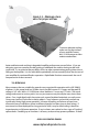
Figure 3.3 - Minimum clearance for proper airflow
3”
3”
To ensure adequate cooling
make sure the top and rear
of your amplifier have at
least 3” of clearance to allow
unobstructed airflow.
hotter and hotter and resulting in degraded amplifier performance or even failure. If you are
designing your own console, consider putting in additional fans and/or ducting to deal with
waste heat. Try to minimize the possibility of dust or other contamination getting drawn into or
falling on the amplifier. It is also advisable to periodically (at least annually) clean the dust out of
your amplifier for continued flawless operation. Alpha Radio Products recommends the use of
compressed air for dust removal.
3.4 Antennas
Many antennas that are suitable for general use are unsuited for operation with a full 1500 W
of power. At this power level in a 50-ohm circuit, the RMS current is 5.5 amps and the peak RF
voltage is 387 volts. With a 2:1 SWR, these values double to 11 amps and 775 volts. The actual
voltage and current at various points in or on your antenna may actually be many times these
values. On a simple dipole with sharp wire ends, corona (localized ionization) can easily occur.
Corona can (and has!) led to fire in nearby objects. Traps in beams and verticals can heat up
significantly during high power operation. Instances of melting or flashover of traps have
occurred in many installations where insufficient thought has been given to their ratings. If
an antenna has been deployed for a long period of time, it may be worth taking it down for
inspection prior to full power operation. If any insulators are cracked or show signs of “tracking”,
replace them. Doubling-up on insulators is also easy to do, and may prevent problems. If there
ALPHA 99 OPERATING MANUAL
www.alpharadioproducts.com
15
is any chance of people, animals or objects coming close to the antenna, take steps to move it
higher, or place barriers so that this cannot happen. Check the SWR of your antenna; if you have a
favorite part of any band you use most often, consider adjusting the antenna for minimum SWR
in this part of the band.
3.5 Coax and Connectors
The importance of a well-constructed feed-line system cannot be overstated. After all, the
purpose of the amplifier is to provide approximately 2 S units (12+ dB) of improvement in your
radiated signal. All too often, installation problems are encountered where cheap, poor or
under-rated coax and connectors are used. These often are responsible for at least one S unit
of degradation. (This means you could have bought a 375 W amplifier and achieved the same
radiated signal by buying good quality feed-line components!) Use the lowest loss 50-ohm
coaxial cable you can obtain. Use new, clean connectors installed according to the manufacturer’s
recommendation. Clean the connectors after soldering them, and before mating them with
the amplifier. Make sure any excess solder is removed from the connector; likewise remove
any fragments of braid etc. Never use old coax, which may have had moisture penetrate under
the jacket. Run the coax in straight lines as much as possible. Support it frequently using noncompressive clips so that it does not hang or stretch under its own weight. Avoid sharp bends
(most manufacturers will specify a minimum bend radius for their product). Make sure the
connection from feed-line to antenna is waterproof. Provide for disconnection of the feed-line
when it is not in use; this protects against damage caused by power surges and lightning strikes,
which are not covered under the amplifier warranty.
3.6 RF Safety
The FCC requires users to check their installations for compliance with published values for allowable
exposure to RF fields. This information is available in ARRL publications, FCC printed rules, and on the
web. Alpha Radio Products strongly recommends that this be done for any installation, both fixed and
at an expedition or contest site.
If you have any questions regarding engineering your 99 into your amateur radio station, please
visit our online technical support website at: www.alpharadioproducts.com
ALPHA 99 OPERATING MANUAL
www.alpharadioproducts.com
16
ALPHA 99 OPERATING MANUAL
www.alpharadioproducts.com
17
4 Unpacking & Preparation
4.1 Unpacking
Inspect both boxes for physical damage. Save all packing material (boxes and inserts) for
possible future use. Contact 303-473-9232 if shipping damage is found. Carefully unpack the
amplifier and transformer.
Carefully remove the amplifier and place it on a workbench or table where you can install the
power transformer. This is a good time to remove the screws on the back panel which lock down
the blower motor for transportation. Retain these screws, as they should be re-installed if the
amplifier is shipped again.
4.2 Installing the Power Transformer
It is recommended that the power transformer be installed when the amp is at or near the place it
is to be used. The chassis of the 99 is designed for the mechanical loads it experiences when the
amplifier is on a flat surface with the tilt-bail up or down. If the amplifier is tilted too far, such that
the transformer is cantilevered or “hanging out” to any degree, the chassis of the amplifier can
distort. This may affect a number of things, from the alignment of screw holes on the top cover
to the band-switch alignment and tension. If the amplifier is moved, even if only from one site to
another locally, remove the transformer to avoid the possibility of damage.
CAUTION:
Do not operate amplifier without the cover in place and all cover screws
installed. Do not operate the amplifier without a good RF ground connection
on the rear panel ground terminal.
ALPHA 99 OPERATING MANUAL
www.alpharadioproducts.com
18
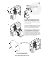
4.2.1 Install the Power Transformer
Place the amplifier on the bench or desk where it is to be used and remove the cover screws and
the cover. Carefully lift the transformer by the handle and move it into place at the rear of the
amplifier., taking care not to bump any of the boards and connectors on the power supply stack.
Locate the set of 4 screws and washers that are supplied with your amp and used to secure the
transformer to the chassis. Next, slide and rotate the amplifier so that the right back corner hangs
over the edge of the bench and insert the screw from the bottom of the amplifier and turn it into
the nut on the transformer plate. Continue this way, rotating the amplifier on the bench until all
of the screws have been inserted and turned. Do not over tighten these screws as doing so may
cause excessive vibrations or noise from the transformer. Figure 4.1 shows an alternate method of
transformer installation.
Once the transformer has been installed and all of the screws are in place holding it to the chassis,
you may proceed to attach the connectors as described in section 4.2.2.
WARNING!
The transformer is very heavy and must be moved with due caution using
only the lifting handle.
CAUTION:
PROCEED SLOWLY to avoid bumping and damaging adjacent wires,
connectors or components.
While the top cover is removed, make sure each tube is firmly seated in its socket, rubber exhaust
chimneys are fully and correctly installed, and anode connectors are tightly clamped to each
tube. The silicone rubber chimneys installed on the 4CX800 tubes are a critical part of the cooling
system. Make sure the chimneys are straight and fully installed so the bottom of the chimney
is firmly against the tube deck and completely covers the airflow openings in the deck. Tube
cooling exhaust must exit only through the tube anode fins; it must not be allowed to escape
outside them. Failure to ensure proper cooling airflow may result in tube damage or destruction,
which is not covered under warranty.
ALPHA 99 OPERATING MANUAL
www.alpharadioproducts.com
19
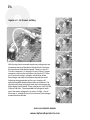
1
2
Figure 4.1
Transformer Installation
1. On a flat surface, with plenty of room, carefully
rotate the amplifier on to its right side (power supply/transformer side). Rotate the transformer onto
its right side, placing the transformer squarely on the
transformer shim (the transformer should overhang
the shim on all sides).
2. Slowly move the amplifier and transformer together making sure to align the nuts on the transformer
with screw holes in the bottom of the amplifier.
3. Once the transformer is settled into position and
the screw holes are aligned, secure the tranformer
into place from the bottom of the amplifier. Insert
the supplied bolts (1/4 / 20, ½” hex bolts) with ¼”
washers through the four clearance holes in the chassis and into the nuts in the transformer base. Once
the transformer is secure you may carefully rotate the
amplfier back to its standard orientation.
3
ALPHA 99 OPERATING MANUAL
www.alpharadioproducts.com
20
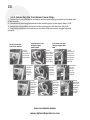
4.2.2 Connecting the Transformer Power Plugs
1. Connect the 9-pin white Molex connector to the matching plug mounted on the back wall
of the amplifier.
2. Connect the 8-pin orange connector to the matching pins on the upper (Mains) PCB.
3. Connect the 6-pin yellow connector to the matching pins on the lower (HV) PCB.
4. Check to be sure that all connector pins on these three connectors engage fully and
correctly.
Transformer to Low
Voltage Supply
(Mains) PCB
AC to Transformer
Connector (Molex)
Found
towards
the back of
the amp &
transformer.
1
1
First make
sure the
connectors are
properly
aligned
Transformer to High
Voltage Supply (HV)
PCB
Found
towards the
front of the
transformer
& the top
rear of the
Mains PCB.
2
First make
sure the
connectors are
properly
aligned
1
Found
towards the
front of the
transformer
& the lower
side of the
HV PCB.
2 First make
sure the
connectors are
properly
aligned
2
3
Gently
but firmly
press the
connectors
together
till they
are fully
mated.
3
Gently
but firmly
press the
connectors
together
till they
are fully
mated.
ALPHA 99 OPERATING MANUAL
www.alpharadioproducts.com
3 Gently
but firmly
press the
connectors
together
till they
are fully
mated.
21
4.2.3 Power Cord Connections
WARNING!
To avoid the hazard of a potentially fatal electric shock and/or severe
damage to the ALPHA 99 and other equipment, always use an AC plug that is
appropriate for the primary mains voltage, current rating and configuration.
NEVER use 120V-type plugs and power receptacles for 190-250V circuits.
ALWAYS use grounding type AC connectors which conform to local codes and ensure that the
green wire in the Alpha 99 power cable is wired only to the AC mains safety ground (or to neutral,
as may be necessary with a 240V circuit configured 120V-N-120V without a separate ground,
commonly found in the US).
The green conductor in the power cord is wired to the ALPHA 99 chassis. It MUST be connected
only to the power source safety ground or neutral. The black and white power cord wires connect
to the two “hot” wires of the AC source; either wire may be connected to either side of the line.
For best results use a dedicated 200-240 V branch circuit of #10 AWG copper wire or equivalent,
rated at 20 A, to feed the amplifier.
4.2.4 Important Information About Operation from 90-130V AC
Electrical power equipment will draw twice as much primary current from 120 V mains as from
240 V mains. Therefore, operating the ALPHA 99 on a typical 120 V/20 A household circuit without
exceeding the 20 A circuit rating will limit maximum peak power output to about 600-1000 W.
Maximum possible RF output power for any particular primary AC voltage and current capacity
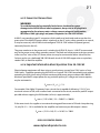
may be estimated as:
Po max = (Vline x Iline) / 2.3
For example, if the Alpha 99 operates from a circuit that is capable of delivering 115 V AC at a
maximum current of 20A, with no other loads connected to the circuit, maximum peak RF output
possible without tripping the 20A breaker (or fuse) is approximately:
Po max = (115V x 20A) / 2.3 = 2300/2.3 = 1000 W
If the same circuit also supplies a transceiver drawing peak line current of 5A and a lamp drawing
1A, only 20-5-1 = 14A is available for the amplifier and maximum possible output is about:
Po max = (115V x 14A) /2.3 = 1610/2.3 = 700W
ALPHA 99 OPERATING MANUAL
www.alpharadioproducts.com
22
4.3 AC Primary Connections
Primary voltage is selected by placing a jumper wire on the proper pin located on the mains
board seated between the transformer and the front panel of the amplifier. See Figures 4-2 and
4-3.
Figure 4-2
External Fan
Interlock
Blower
Transformer AC
Connector
Tubes
Vacuum Relay
RF Choke
Crowbar
Tank coil
Band switch
Power Supply
Mains Board
Below are some considerations at the high end and the low end of this voltage range that are
rarely encountered.
Low Voltage vs. Power Output
At the low end of the voltage range, do not expect to be able to get 1,500 watts output if your
line voltage is below 110 volts. If your line voltage is between 110 and 130 volts, then 1,500 watts
PEP operation (CW or SSB) may be possible if your AC line service has sufficient current capacity
(30 amp circuit recommended). However, 1,500 watts continuous should not be expected. If
your line voltage is between 90-110 volts, then power outputs above 1,000 watts should not be
expected from the amplifier. Tune (adjust) the amplifier for no more than 1,000 watts output, and
simultaneously for maximum efficiency.
ALPHA 99 OPERATING MANUAL
www.alpharadioproducts.com
23
Low Voltage vs. Current Draw
If either of the two low voltage taps is used, be aware that the amplifier is normally shipped
fused with 20A/250V fuses. You may want to consider replacing these with 25A/250V “slo-blo”
fuses for very low line voltages (less than 100 volts). If you do, be aware that the higher current
at the lower voltage will significantly warm the power cord for the amplifier. The cord (as well
as fuse holders and some internal connectors) are operating near their maximum ratings due
to the current demand at lower voltages. Be sure that the AC cord is not coiled too tightly or
placed where normal air flow is restricted because the cord could overheat. If other equipment
is drawing current from the same circuit as the Alpha 99, then the considerations in section 4.2.3
should be taken into account.
High Voltage and Tube Life
At the high end (sometimes encountered when using poorly regulated generators) the plate
voltage and tube heater voltage may be too high. If voltages above 250 volts are applied for any
length of time, the lifetime of the tubes may be reduced. If this is your situation, the first line of
defense is to contact your utility company and ask if they can reduce your line voltage. If this is
not possible, you may want to consider placing your own step-down transformer in line between
the AC outlet and the amplifier. If this is necessary, a transformer with at least 4-kVA rating is
required, due to the nature of the current waveform in the primary. Another choice for voltage
control, a ferro-resonant voltage regulator, is an expensive solution, but is a good way to stabilize
primary voltage.
Note: If you intend to operate the amplifier on any of the 90 - 130V settings, the two lower 2
amp fuses on the rear panel will have to be changed to 5 amp to allow for the increased in-rush
current.
ALPHA 99 OPERATING MANUAL
www.alpharadioproducts.com
24
Figure 4-3 - AC Power setting
240 V
220 V
200 V
With the top cover removed, the primary voltage taps are
located on the top of the Mains Board, which is between
the transformer and the front panel. There is a row of 5
“fast on” connectors (J1 through J5) and a “flying” jumper
connector which mates with them. See Figure 4-3. There
are 5 “nominal” primary voltages, which cover all the
line voltages normally encountered around the world.
Selecting the appropriate tap for your situation will
optimize amplifier performance, safety and lifetime. The
nominal mid-range voltage for each tap is printed on the
Mains Board circuit board. These voltages are 100,120, 200,
220 and 240 Volts. The acceptable line voltage for each
tap is the center voltage plus or minus 10 Volts. One of
these taps is suitable for any of the “nominal” line voltages
encountered worldwide.
ALPHA 99 OPERATING MANUAL
www.alpharadioproducts.com
120 V
100 V
25
4.4 Complete the Transformer Installation
4.4.1 RF Grounding
A ground stud with wing nut is provided on the rear of the chassis. Connection should be made
from this stud to a good RF earth ground, such as a copper water pipe or driven rod, via heavy
copper braid or strap.
CAUTION:
When using any high power amplifier, failure to connect ALL station
equipment to a good common ground may allow RF feedback to leak into the
transceiver and cause severe signal distortion.
4.4.2 Replacing the Amplifier Cover
Replace all attachment screws. Use only the 6-32 screws supplied with the amplifier and do not
tighten any of the screws until all are started. Do not attempt to operate the amplifier with the
cover removed or only placed back on the unit without the attachment screws. This WILL cause
damage to the Alpha 99 and may also lead to injury or death to the operator.
4.4.3 Blower Preparation
The cooling fan is secured to the rear panel for shipping. Be sure to remove the fan shipping
hardware (two 10-32 bolts, fiber washers, rubber shim) from rear chassis wall. Save this hardware!
It must be reinstalled whenever the chassis is transported.
4.5 Amplifier/Station Interconnections
Once the power transformer is installed, properly configured, and the cover replaced, place the
amplifier in its operating position. The amplifier with the transformer installed is heavy so you
may need assistance to safely move it. Make sure it is placed on a stable surface and that there is
sufficient space to the rear, sides, and top to allow good air flow and safe placement of cables.
4.5.1 Coaxial Cable Types & Connectors
Connect the transceiver RF output to the ALPHA 99 RF INPUT connector with 50-ohm coaxial cable- RG-
ALPHA 99 OPERATING MANUAL
www.alpharadioproducts.com
26
58C/U or equivalent. A 6 ft. cable is supplied for this purpose.
Coaxial cable from the 99 RF OUTPUT connector to the antenna should be RG-8A/U, RG-213/U, or
equivalent high quality type with a PL-259 UHF-type plug on the amplifier end. RG8X cable is not
recommended, as it is not rated for 1500 watts.
4.5.2 T/R Control Cable
The Alpha 99 has a full break-in vacuum relay QSK system requiring only the normal interconnection
when used with a modern QSK transceiver. The Alpha 99 requires a contact closure (short circuit) on
transmit from its RELAY jack center pin to chassis. This function is supplied by the transceiver, usually
from a dedicated relay that is normally open in receive and closed in transmit. Shielded wire should
be used for the T/R control cable. The Alpha 99 end must be fitted with a common phono (RCA-type)
plug and the other end with a connector suitable for the transceiver.
The T/R relay contact must close before application of RF drive. The Alpha 99 protection circuitry
prevents “hot-switching” with RF drive applied. Modern transceivers have the proper time delay
between key up and the start of the transmitted signal to allow the Alpha 99 to follow the CW keying.
If a T/R timing problem is suspected, connect the CW keyer to the RELAY jack on the Alpha 99, and
connect a cable from KEY OUT on the amplifier to the keying input of the transmitter.
4.5.3 ALC
Alpha Radio Products does not recommend connecting the ALC on your Alpha 99 to your exciter.
ALPHA 99 OPERATING MANUAL
www.alpharadioproducts.com
27
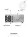
Key In line from
radio
Key Out line (optional) to radio
RF output to antenna
1500 watts
RF input from radio
50-60 watts
ALPHA 99 OPERATING MANUAL
www.alpharadioproducts.com
28
ALPHA 99 OPERATING MANUAL
www.alpharadioproducts.com
29
5 Theory of Operation
5.1 Theory of Operation - Overview
The Alpha 99 uses tetrode vacuum power grid tubes as the amplifying devices. The main power
supply is an unregulated transformer/rectifier/capacitor power supply for the high voltage
(HV) and heater circuits. All other power supplies are regulated. There are 8 circuit cards in the
amplifier. In addition to these, the tubes, tank circuit assembly, and transformer complete the
main sections of the amplifier. These major blocks are described below.
5.2 Tubes
The amplifier is designed to use two GU74B tetrode tubes. The Svetlana Company of St.
Petersburg, Russia manufactures these tubes. The amplifier design uses these tubes well within
their ratings. At the time of manufacture, these tubes are available as “new military surplus” (NMS)
devices. According to Svetlana, the 4CX800A tube is a direct commercial replacement for the
GU74B. The two tubes are operated in parallel, and the Alpha 99 is designed with the expectation
that a matched pair of tubes will be used in the amplifier. Alpha matches tubes received from the
supplier to within 10% for power output and gain when operated in a standardized test fixture.
Note that power output, efficiency, tube life and amplifier reliability may be compromised if tubes
are used that do not meet Alpha’s matching criteria. Any damage sustained as a result of using
unmatched tubes may not be covered under warranty. The tubes are operated in Class AB1, with
a plate voltage of 2,500V (nominal, full output, key down), a grid 1 voltage of 50-60 volts, and a
grid 2 voltage of 340-360 volts. Each tube has a 15-ohm low-inductance resistor in series with its
cathode. This resistor stabilizes the tube bias and provides negative feedback, which improves
linearity (and hence IM performance). Electronic bias switching (EBS) increases the negative grid
1 voltage in pauses in speech or between Morse code elements. This reduces the standing bias
on the tubes, resulting in less waste heat, longer tube life and higher overall amplifier efficiency.
The artifacts of EBS are not noticeable under normal communications conditions.
5.3 Output Tank Circuit
ALPHA 99 OPERATING MANUAL
www.alpharadioproducts.com
30
The output tank circuit of the Alpha 99 is designed to provide reliable high efficiency, low
distortion performance in a very compact volume. The basic topology is “pi-L”, which provides
harmonic attenuation adequate to meet the requirements of all countries globally that permit
power outputs of 1,500 watts. Band switching is under manual control and is accomplished by
a four-wafer band switch. Three of these wafers are used as multi-function tap selectors, which
simultaneously select band taps on the inductors and include varying amounts of capacitance to
provide band-spread on the tune and load capacitors. These three wafers are in the RF tank area.
The fourth wafer is inside the front sub-chassis and is used by the control board to determine
which band the user has selected.
5.4 Tube Deck
The tube deck is a mechanical assembly built around the tube deck PCB. The tube deck PCB has
the tube sockets mounted on it, as well as those critical circuit elements that need to be in close
proximity to the tubes. The tube sockets contain integral screen grid (grid 2) RF bypass capacitors.
Also on this PCB is the input bypass relay. This relay is under microprocessor control and in one
position switches the input RF to the tubes and in the other it switches the input RF to the tube
matching circuit. The tubes are operated as a “swamped grid” tetrode design. The tube grids
are tied at RF to a 50-ohm swamping resistor, which absorbs most of the input drive power. The
RF voltage across this resistor is added to the grid 1 DC bias to provide the net low-impedance
tube grid 1 bias. The RF impedance represented by grid 1 and its capacitance is compensated
for by a series inductance to provide less than 2:1 SWR on each band at the amplifier’s input. At
higher frequencies, a relay shorts out some of this compensating inductance. This relay is under
microprocessor control and is actuated according to the band switch setting.
5.5 Mains Board
The power supply functions are split between the mains board and the high voltage (HV) board.
The mains board mostly deals with the primary side of the transformer. The various taps for the
transformer primary are routed through this board and so is the AC line input. Relays on the
mains board connect the AC line to the appropriate taps on the primary. One of 5 tap options is
selected by using a 5-way jumper field. See section 4.3 for more details on how to set the jumper.
Also on the mains board is a step-start circuit. This circuit consists of a relay and a resistor, which
are time-sequenced to limit the inrush current into the amplifier when it is first turned on. When
initially turned on, the tap relays operate from a voltage derived from resistors from the AC line.
They hold via contacts on the trip relay on the HV board. The regulated minus12 volt and minus
124 volt supplies are also located on this board.
5.6 High Voltage Board
ALPHA 99 OPERATING MANUAL
www.alpharadioproducts.com
31
The main high voltage for the amplifier is created on this board using a full-wave bridge rectifier
and a bank of capacitors. This power supply has two 10-ohm resistors, one in the positive (B+)
lead, and the other in the negative return, which goes to ground. The combination of these two
resistors limits the surge current in the case of a B+ arc. The voltage across the resistor in the
negative return is used to monitor tube plate current in the control board. This voltage is also
used to generate the “hard fault” condition. When the power supply current exceeds about 2
to 2.5 Amps, a relay operates to open the coil circuit of the mains tap relays on the mains board.
When these relays release, the amplifier goes to the power-off state. This hard fault circuit
operates independently of microprocessor control. The regulated screen supply is also located on
this board. It consists of a string of Zener diodes and a series-pass N-channel MOSFET. All power
supply filter capacitors on this board have bleeder resistors which will discharge the capacitors in
less than 60 seconds. If it is necessary to work on this board, it is nevertheless recommended that
the discharged condition be confirmed with a voltmeter, due to the remote possibility of bleeder
resistor failure.
5.7 Control Board
The control board is the heart of the amplifier. It contains all of the bias, control and safety
circuitry for the Alpha 99. All tube bias conditions are set on this board, as well as transmit and
receive timing. All critical safety parameters, such as plate current, amplifier gain and reflected
power are monitored on this board. These parameters are set at the factory and there are no user
adjustments recommended or desired.
5.8 Display Board
This board converts analog voltages into linear bar graph displays for the front panel. It receives
these voltages from the control board. Various discrete LEDs are also on this board.
5.9 Output Wattmeter Board
This is a transformer-coupled reflectometer with diode detectors. The outputs from this board
are DC voltages corresponding to the forward and reflected power sensed by the reflectometer.
These voltages are connected to the control board. There is a trimmer capacitor on this board.
This capacitor is adjusted with the amplifier operating into a good 50-ohm dummy load. The
capacitor is rotated to minimize the reflected power voltage. The board also has an 800V
protection device on the RF output. This is located between the PCB and the flange of the output
connector.
ALPHA 99 OPERATING MANUAL
www.alpharadioproducts.com
32
5.10 Center Partition Board
This contains the RF decoupling circuit on the B+ line as well as the “crowbar” safety circuit. This
safety device consists of a piece of spring metal, which shorts out the B+ line when the top cover
of the amplifier is removed.
ALPHA 99 OPERATING MANUAL
www.alpharadioproducts.com
33
6 Operation & Maintenance
The ALPHA 99 is extremely easy to operate, but failure to carry out each procedure
exactly as described in this manual is likely to lead to amplifier damage, which is
not covered under warranty. Damage to other station equipment may also result.
6.1 Before Operating Your Alpha 99
6.1.1 Setting Input Drive
You must set the transceiver output power properly. Virtually all damage to date has resulted
directly from severe overdrive. The ALPHA 99 requires about 50 W drive for full rated output.
Damage caused by applying several times rated drive power to the ALPHA 99 will not be
covered under warranty. Fortunately, most modern transceivers maintain quite consistent
output from band-to-band and mode-to-mode when set up properly.
CAUTION:
Setting only the transceiver POWER or RF PWR control IS NOT SUFFICIENT.
Several popular transceivers can generate RF spikes of 200-300 W. Control of
these spikes typically is done with a knob labeled DRIVE (IC-781, FT-1000) or
PROCESSOR OUT (TS-940, TS-950). On SSB, when speech processing is not used,
adjust the MIC or MIKE controls. See the operator’s manual for your particular
transceiver.
6.1.2 Dealing with Faults
The ALPHA 99 “faults” into STBY or OFF when unsafe operating conditions occur. This is
shown when the amplifier changes from the OPR LED being ON to the Fault and STBY LEDs
turning ON instead (soft fault), or when the amplifier shuts off completely (hard fault).
ALPHA 99 OPERATING MANUAL
www.alpharadioproducts.com
34
One of four situations will typically result in a fault:
• Incorrect gain. Output too low or too high for the input power supplied.
• High reflected power (SWR).
• Incorrect plate voltage (too high).
• RF arc in output circuit including antenna.
If the tube current exceeds about 2.5 amps, the amplifier is shut off completely- that is, the AC
is shut off. The ON/OFF switch will need to be used to put the amplifier back on line. To avoid
problems, wait at least 20 seconds after this occurs before attempting to put the amplifier
back on line. If the amplifier trips again immediately, investigate and cure the problem before
attempting to turn the amplifier on again.
Repeatedly hitting the ON switch when the amplifier trips out is likely to result in severe damage
to components in the amplifier.
If a hard fault trips the amplifier all the way OFF, wait at least 20 seconds before turning the
amplifier power on again.
If you are certain that you have taken care of the problem that caused the fault, you may turn the
amplifier back to operate and proceed with use.
6.1.3 High SWR Considerations
On any frequency where your antenna VSWR exceeds 1.5:1, it’s important to carefully tune
the ALPHA 99 for a proper match. The ALPHA 99 does not contain an antenna tuner. The SWR
can be tuned via the antenna or an external tuner connected to the output of the Alpha 99.
Nevertheless, if the system SWR is below 2:1, the additional RF power loss of an antenna tuner can
be avoided by tuning the 99 into the slight mismatch. There is no advantage to using a tuner to
“tweak” the last bit of SWR - in fact you will lose power this way.
6.1.4 Operating at Less Than 1.5 kW Requires Retuning
If you tune the amplifier for maximum power output and then decide to operate the 99 at
a power output much different from 1.5 kW, it must be re-tuned for efficient and RF-clean
operation. Under such “lightly loaded” conditions, the green grid LED will probably be fully lit.
Note that if you tune the amplifier at 1,500 watts and then simply reduce power to 1,000 watts,
the tubes are actually going to run hotter than at 1,500 watts. It is better to tune the amplifier
with close to 50 watts of power, but reduce the loading control to get 1,000 watts.
ALPHA 99 OPERATING MANUAL
www.alpharadioproducts.com
35
6.1.5 Lightning Protection
Induced energy from nearby electrical storms or other power transients may damage
components. Such damage is not covered under warranty. It is important to use a good
lightning arrestor, however the only lightning proof solution available is to disconnect
antenna feedlines and AC power when the equipment is not in use.
6.1.6 Operating in Bypass Mode
Whenever the 99 is in line, either off, in standby (STBY), or in warm-up with the WAIT LED lighted,
the amplifier is bypassed and the exciter is connected directly to the antenna. The throughput
limit in all cases is 150 watts. Any power level more than this may damage the RF switching relays
in the 99.
6.1.7 Never Use Transceiver Automatic Antenna Tuner
Never use an automatic antenna tuner into or through the 99. This will cause damage to the
Input wattmeter and Input T/R Relay. Note that many popular transceivers have built-in antenna
tuners that should be disengaged when driving your amplifier or transmitting through the
amplifier with the amplifier in bypass mode.
6.2 Transceiver Connections
The following is a list of popular transceivers and considerations for their connection to the
ALPHA 99 amplifier. Contact Alpha Radio Products Customer Service for advice on other
transceivers.
Table 6.2 Typical Transceiver Connections
Transceiver
Icom
Yeasu
Connection and Keying Information
RF –
T/R – Connection with the “Send” jack. See the transceiver User’s
Manual for information.
RF –
T/R – Connection with the RCA “TX GND” connector. Also with the
DIN “Band Data” connector. See the transceiver User’s Manual for
information.
ALPHA 99 OPERATING MANUAL
www.alpharadioproducts.com
36
Kenwood
Older Transceivers
RF –
T/R – See the transceiver User’s Manual for information on
connecting to external amplifiers.
See the transceiver User’s Manual for information on connecting
to external amplifiers.
6.3 Initial Setup & Tuning
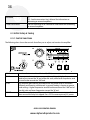
6.3.1 Control Functions
The following chart shows the controls that allow you to adjust and monitor the amplifier.
BAND
TUNE
LOAD
POWER
Used to select amateur band desired (in MHz).
Sets output tank circuit to resonance within each band. Higher frequencies
tend to tune toward the “0” end of the dial scale, while lower frequencies tend
to tune further toward the “100” end.
Sets amplifier plate loading and determines the power level at which best
efficiency and linearity are achieved. In general, loading is heavier at greater
scale settings. Higher frequencies tend to load more toward the “100” end of
the dial scale and lower frequencies toward the “0” end.
Press ON to apply primary AC power to the amplifier or to reset power if the
plate overcurrent relay has tripped. Press OFF to remove primary AC power.
ALPHA 99 OPERATING MANUAL
www.alpharadioproducts.com
37
OPR/STBY
Metering LEDs
& Bargraphs
RF OUTPUT
& REFLECTED
POWER
TUNE
Ip
HV
Operate (OPR) places the amplifier in-line.
With the 99 off, in standby(STBY), or in warm-up with the WAIT LED lighted, the
amplifier is bypassed and the exciter is connected directly to the antenna.
Separate bargraphs provide instantaneous full-time display of peak values.
Red and green “GRID” LEDs indicate, respectively, that normal peak drive has
been reached, and the onset of overdrive and flattopping. A switch-selected
bargraph monitors three additional functions.
Permits a simple and safe tune-up procedure to be performed at low output
power. See section 6.3.2 Tune-Up.
Plate current, 1.5 amperes full scale (approximately 75 mA per segment).
Plate voltage, 3000 VDC full scale (150 V per segment).
6.3.2 Tune-Up
The objective of tune-up is to adjust the amplifier (and the drive applied to it) to obtain optimum
efficiency and linearity at the desired output power. Any linear amplifier must be adjusted for
optimum efficiency and linearity at each specific power level. If operation at higher power is
then attempted without appropriate readjustment, the result will be flattopping, “splatter,” and
(usually) excessive amplifier grid current. If operated at a much lower power level than it has
been adjusted for, the amplifier’s efficiency decreases considerably. Recommended practice is
to tune first into a dummy load or artificial antenna, then connect the antenna and make any
slight final adjustments that may be needed. Alpha Radio Products makes the ALPHA 2100 in-line
dummy load which simplifies this process. Using the AP 2100, the operator can switch between
the dummy load and the antenna at the flip of a switch.
6.3.3 Grid Current Information
The ALPHA 99 operates in Class AB2 when delivering maximum output power consistent with excellent
linearity. A small amount of grid current flows and the green GRID MIN LED illuminates as drive
approaches the optimum level. The green GRID LED will flicker on SSB voice peaks, and illuminate under
CW/SSTV/RTTY carrier conditions.
As overdrive approaches, grid current increases rapidly and the red GRID MAX LED illuminates. At
maximum output and efficiency, the red LED lights dimly; full illumination of the red LED indicates
overdrive and must be avoided. If the red LED lights up before the desired value of plate current and/or
power output is reached, readjust amplifier loading before continuing.
ALPHA 99 OPERATING MANUAL
www.alpharadioproducts.com
38
On SSB, optimum output consistent with good linearity occurs when the green GRID LED
illuminates on most voice peaks and the red LED flickers dimly on only the highest peaks.
Excessive grid current results from overdrive and/or inadequate loading. The solution is to reduce
drive, and/or increase amplifier loading. The 99’s 4CX800A/GU74b tubes are well protected and
these adjustments tend to be less critical than in many other amplifiers. Grid bias is stabilized
against grid current fluctuations.
6.3.4 ALC
The 99 grid current limiting circuits provide substantial tube protection against possible damage,
therefore no ALC control is necessary. It is only necessary to set the drive power from the radio as
detailed in this manual.
6.3.5 Turning On The Amplifier
Please Note: Every time the ALPHA 99 is powered up there is a built-in 150 second warm up wait.
1. Place the OPR/STBY switch to STBY (standby).
2. Rotate the multimeter selector switch to HV.
3. Depress the POWER/ON switch. For about two seconds the bar graph displays and the
LEDs on the front panel will be lit randomly as the microcontroller goes through its startup sequence. The fan and blower should immediately begin to operate. If there is no air
flow from the amplifier and no sound of blower operation, immediately turn the amplifier
off and investigate.
4. After the two-second period, the HV display should be all the way to the right, certainly
above 2,500 Volts. If it is lower than this, investigate further- perhaps the primary taps are
not correctly set.
5. Move the multimeter switch to the Ip position. There should be no current indicated,
and this should be true during the entire period the amplifier is warming up. Leave the
switch in the Ip position during amplifier warmup. The “Wait” LED will be blinking about
twice per second, indicating that warmup is still in progress. The FAULT, OPER and STBY
LEDs should not be illuminated.
CAUTION:
EXHAUST AIR MUST BE DETECTABLE FROM BOTH TOP VENTS.
If exhaust air is not coming from the top vents, TURN OFF the amplifier immediately and verify
that the exhaust chimneys are properly positioned over the tubes. When the warm up delay is
complete (about 150 seconds), the WAIT LED will extinguish. Put the OPR/STBY switch to OPR and
ALPHA 99 OPERATING MANUAL
www.alpharadioproducts.com
39
ALPHA 99 is now “ready”.
6.3.6 Tuning the Amplifier
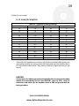
Band (MHz)
1.8
1.8
3.5
3.5
3.5
7
10
14
18
21
24
28
28
28
Table 6.3 – Preliminary Tune-up Settings
Frequency (MHz)
Tune
1.8
60
2.0
20
3.5
67
3.75
58
4.0
50
7.15
45
10.13
15
14.2
70
18.1
50
21.2
40
24.9
65
28.0
32
28.6
24
29.7
18
Load
14
65
40
60
75
35
26
40
55
65
60
72
74
76
*Each ALPHA 99 shipped from our factory will include an individual table showing the
tune and load settings we used to achieve full output power on that amplifier into an
AP 2100, a 50-ohm dummy load. These settings usually vary slightly from those in the
manual.
CAUTION:
If at any time in the following procedure the amplifier fails to respond as described,
remove drive immediately and turn the OPR/STBY switch to STBY! Verify all
connections and cables, turn the amplifier switch to OPR and proceed with the
tuning procedure.
ALPHA 99 OPERATING MANUAL
www.alpharadioproducts.com
40
Alpha Radio Products recommmended tune up procedure.
“Dip and Load” Method
Tuning up for Operation at 1,500 W RF Output.
Preset BAND, TUNE, and LOAD controls to the nominal positions given in your amp’s specific tune up
table or Table 6.3:
Note: Final TUNE and LOAD settings will vary with the operating frequency, antenna characteristics and
power level.
1. Please limit the transceiver drive to about 65W for tuning up and operating the amp.
2. Set Multimeter to Ip (Plate Current). Set TUNE and LOAD controls to numbers indicated
in the tuneup sheet originally included with the amplifier.
3. Key radio with 20W drive and adjust TUNE control for a peak in RF out which should
be at the same point as a dip in Ip.
4. Increase drive to get 1000W output, going back and forth between the TUNE and
LOAD to peak the RF output. If more output is desired, increase drive from radio slightly,
increase LOAD for a peak in RF out, then peak RF out with TUNE control.
5. When the amplifier is tuned correctly on 160m thru 40m, the Ip should range between
0.9A and 1.1 A (read on the 0-to-1.5A scale) for 1500W output, and input drive should not
need to be more than about 60W. On 20m the Ip will usually be about 1.0A for 1500W
output.
6. Plate current (Ip) is the most useful parameter to monitor on the multimeter bargraph
during normal operation of the amplifier.
Alpha Radio Products alternate tune up procedure.
“Nominal Gain” Method
Tuning up for Operation at 1,500 W RF Output.
Preset BAND, TUNE, and LOAD controls to the nominal positions given in your amp’s specific tune up
table or Table 6.3:
ALPHA 99 OPERATING MANUAL
www.alpharadioproducts.com
41
Note: Final TUNE and LOAD settings will vary with the operating frequency, antenna characteristics and
power level.
1. Reduce transceiver carrier output control to ZERO.
2. Press OPR (operate) on OPR-STBY switch. OPR LED should illuminate.
3. Select the TUNE function of the multimeter bargraph.
4. Switch transceiver to CW and increase its carrier output to approximately 15 W (99 output will
be approximately 300-500 W).
5. Adjust the TUNE control to deflect the TUNE LED maximum rightward.
6. Adjust the LOAD control to place the illuminated TUNE LED near the “V” mark on the TUNE
scale.
7. Repeat steps 5 and 6 at least twice.
8. Increase the excitation power until the 99 output is about 1500 W.
9. Repeat steps 6 and 7 at least twice.
10. Touch up the TUNE for maximum power output.
11. The ALPHA 99 is now correctly tuned to deliver 1500 W RF output on SSB, CW, FSK, SSTV and
FM. The TUNE LED normally fluctuates during modulation or keying. Illumination of the first red
LED on the RF OUTPUT bargraph indicates output has exceeded 1500 W. The tune LED may vary
during standard opertaion, especially SSB. This is normal.
6.4 Normal Use
6.4.1 Tubes
The 4CX800A/GU74b tubes used in the ALPHA 99 are supplied as a matched pair. They are very
rugged and normally operate with a large margin of safety. They should provide outstanding
service for many years if not damaged by abuse - such as overdrive or blockage of cooling airflow.
ALPHA 99 OPERATING MANUAL
www.alpharadioproducts.com
42
Allow at least three to four inches (10 cm) of unobstructed clearance around the air intake and
exhaust areas. Stacking equipment on top of the amplifier is not recommended.
Never allow key-down plate current to exceed 1.5 A for more than one or two seconds. If you
do, and a plate current trip occurs, it will automatically reset in about 4 seconds if the amplifier is
returned to receive (key-up).
Never allow the red GRID LED to stay brightly illuminated for more than a second.
Frequent on-off AC power cycling may shorten the tubes’ life. It is less stressful to leave
equipment in standby for several hours than to cycle power repeatedly on-off-on-off over the
same period.
6.4.2 Interlocks
The ALPHA 99 is equipped with a cover interlock switch intended to remove primary power from
the amplifier, and a crowbar to short-circuit the high voltage to chassis whenever the cover is
lifted. These interlocks are designed to protect against dangerous electric shock resulting from
accidental contact with the lethal voltages inside the amplifier.
WARNING!
ALWAYS DISCONNECT THE AC LINE CORD FROM THE POWER SOURCE BEFORE
REMOVING THE TOP COVER FROM THE 99 FOR ANY REASON!
Cover interlocks are intended only as back-up protection against accidents. Never depend
on them! Always disconnect the power cord from the AC mains before removing the cover!
Interlock switches should not be disabled for any reason.
6.4.3 Fuses
Never replace any fuse with one of a different type or greater current rating. Blowing of one
or both primary line fuses indicates that the maximum safe average power capability of the
amplifier has been substantially exceeded or that an equipment failure has occurred. USE ONLY
20 AMP, 250 VOLT RATED FUSES for 190-220 VAC service. 25 amp fuses may be used with caution
for line voltages of 90-130V.
The slow-blow fuse F3, located below the primary line fuses, may prevent damage to the stepstart resistors and HV rectifiers in the event of abnormal turn-on conditions or HV faults. If the AC
interlock is defeated and primary power is applied while the HV crowbar is closed, the step-start
ALPHA 99 OPERATING MANUAL
www.alpharadioproducts.com
43
fuses will normally blow.
CAUTION:
DAMAGE RESULTING FROM USE OF A FUSE OF INCORRECT SIZE OR TYPE WILL
NOT BE COVERED UNDER WARRANTY AND MAY VOID THE WARRANTY.
6.4.4 Plate Overcurrent Relay
This relay will quickly turn off the amplifier in the event of grossly excessive plate current or fault
in the high voltage circuitry. The relay will not prevent tube or other damage due to either short
or long term overdrive or improper tuning. It is the operator’s responsibility to ensure safe tuning,
drive, and general operating conditions. Should the overcurrent relay trip, remove AC power from
the amplifier, then determine and correct the cause of the trip before turning the 99 on again.
This “hard fault” trip circuit does not rely on the microntroller for it’s operation, and will protect
the amplifier even if the processor has been damaged or is malfunctioning.
6.4.5 Idling Plate Current and Electronic Bias Control (Ebs)
Idling plate current of the ALPHA 99 is approximately 350 to 400 mA during full power
transmission. A detector senses RF drive, and reduces plate current to 30-50 mA during pauses
in speech and key-up intervals, thus substantially reducing average power supply loading, heat
generation, and wasted energy.
6.4.6 RF and Mistuning Protection
The ALPHA 99’s exclusive circuit senses the beginning of any RF arc in, for example, a TUNE
or LOAD variable capacitor and automatically switches the amplifier to standby within a few
milliseconds. This system has virtually eliminated RF arc damage in current ALPHA amplifiers. The
system similarly detects severe miss-tuning of the 99, and if drive exceeds about 25 W switches
the amplifier to standby. The 25 watt input trip threshold permits safe tune-up at low power
levels without aggravating and unnecessary trip-outs.
6.5 Standard Maintenance Tasks
The amplifier interior, particularly high voltage areas, should be cleaned with a vacuum cleaner
and a soft bristle brush frequently enough to prevent visible accumulation of dust. In extremely
dusty conditions it may be advisable to secure a thin air filter of the type used for window air
conditioners across the air intake on the rear panel.
ALPHA 99 OPERATING MANUAL
www.alpharadioproducts.com
44
There are no user-accessible lubrication points in the amplifier. Do not apply oil or grease to
any of the components. The exterior of the ALPHA 99 may be cleaned with a mild household
liquid detergent. Do not use chemical solvents, as these may severely damage the front panel or
cabinet finish. Never use an abrasive cleaner.
ALPHA 99 OPERATING MANUAL
www.alpharadioproducts.com
45
7 Troubleshooting Hints
7.1 Normal Troubleshooting
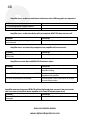
99 will not turn on; nothing happens when ON switch is pushed.
Problem
1) External AC wiring, fuse or circuit breaker
may be open.
2) Amplifier cover is not in place or properly
secured; cover safety interlock is open.
3) Fuse F1-F4 open or missing. Check fuses
with an ohmmeter.
4) Step-start resistor open.
Correction
Check & correct wiring, replace fuse, or reset
circuit breaker.
Make sure cover is replaced and all screws
securely inserted.
Check and replace any blown fuses with fuses
of the same size.
Check resistor. If damaged, replace.
Amplifier turns on but no HV is indicated by the multimeter LED bargraph.
Problem
1) Multimeter selector switch in wrong
position, e.g., Ip.
2) Possible HV circuit fault.
3) HV sampling resistor in power supply
damaged.
4) Transformer plugged into power supply
incorrectly.
Correction
Set Multimeter switch to the correct position.
Check power supply wiring and connectors to
be sure input and output connectors are set
properly and the voltage taps have been set
properly.
ALPHA 99 OPERATING MANUAL
www.alpharadioproducts.com
46
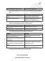
Amplifier turns on but no multimeter indication; other LED bargraphs are operative.
Problem
1) Low voltage power supply problem.
2) Defect or damage on control board.
Correction
Amplifier turns on but time delay will not complete; WAIT LED does not turn off.
Problem
1) Defect or damage in timing circuitry on
control board.
Correction
Contact Alpha Customer Service.
Amplifier turns on, time delay completes but amplifier will not transmit.
Problem
1) Open T/R control line from transceiver to
RELAY jack.
Correction
Contact Alpha Customer Service.
Amplifier transmits but red GRID LED illuminates often.
Problem
1) Amplifier overdriven or under-loaded.
Correction
Reduce transceiver output and /or increase
amplifier loading.
2) Load VSWR (reflected power) exceeds 200 W. Check output cabling and antenna. Correct
impedance mismatches.
3) Exciter output poorly controlled.
Consult exciter’s User’s Manual for assistance
on controlling output.
Amplifier operates but green GRID LED will not light and plate current is low; transceiver
does not seem to be able to drive amplifier to its rated RF output power level.
Problem
Correction
1) Input RF load resistor or bias circuitry
Contact Alpha Customer Service.
damaged.
ALPHA 99 OPERATING MANUAL
www.alpharadioproducts.com
47
2) Possible damaged or defective tube(s).
Contact Alpha Customer Service.
Receive signals disappear or are severely attenuated when switching from STBY to
OPR.
Problem
1) RELAY (T/R) control cable from transceiver is
shorted.
2) Transceiver locked in transmit
Correction
Check T/R control cable to make sure it is
switching properly. Replace if needed.
Make sure transceiver is properly switching
between transmit and receive. See
transceiver’s User’s Manual for assistance.
Plate current indicated when amplifier is in STBY or receive.
Problem
1) 4CX800A/GU74b tube heater-to-cathode
leakage or short.
2) Tube bias supply or T/R bias switch faulty.
Correction
Contact Alpha Customer Support.
Contact Alpha Customer Support.
Distorted SSB signal; possible severe television interference.
Problem
1) Excessive RF drive from transceiver and/or
insufficient amplifier loading.
2) Coaxial connector, coax feedline, antenna
feedpoint balun, tuner, or antenna trap arcing
on voice peaks.
3) RF feedback from antenna into transceiver
via the transceiver power cord, microphone or
key cable, or other unshielded station patch
cables.
4) Poor station RF ground.
Correction
Decrease drive from transceiver. Re-check
amplifier tuning.
Make sure all power cords, microphone
and key cables, or other cables are properly
shielded and grounded.
Be sure the amplifier and transceiver have a
proper RF ground. Correct if necessary.
Low frequency (60 Hz) audio hum on transmitted signal.
ALPHA 99 OPERATING MANUAL
www.alpharadioproducts.com
48
Problem
1) Defective microphone cord (especially, a
broken ground lead).
Correction
Check to be sure microphone cord has not
broken or does not have defective leads or
connectors.
2) Dynamic (magnetic) microphone located
All dynamic microphones pick up some
within about two feet of 99 power transformer. magnetically coupled hum from the external
field of nearby power transformers. In cases
where objectionable hum is experienced
while using the 99 and popular microphones
such as the Heil series, the problem usually
can be resolved by keeping the microphone
at least 18 to 24 inches from the front of the
amplifier and ensuring that transceiver mike
gain and speech processing levels are not
adjusted to exceed 10 dB. In rare cases it may
be necessary to use a ceramic or condenser
type microphone.
Grid bias is unexpectedly decreasing.
Problem
1) Nominal grid bias current is 380 mA. If
the normal bias is decreasing, the tubes are
probably aging.
Correction
Contact Alpha Customer Support to see if
tubes need replacing.
Required drive to maintain 1,500 W is steadily increasing.
Problem
1) If the amount of drive required to maintain
1,500 watts is steadily increasing, this is an
indication that the tubes are probably aging.
Correction
Contact Alpha Customer Support to see if
tubes need replacing.
ALPHA 99 OPERATING MANUAL
www.alpharadioproducts.com
49
8 Glossary
The following terms are used in this manual. Detailed explanations may be found in various
publications including the ARRL Handbook.
AB1-
Modulation class AB1. Provides good linearity in push-pull configuration.
AC-
Alternating current
ALC-
Automatic Level Control
ampere-
Current measurement
ARRL- American Radio Relay League
AWG-
American wire gauge
CW-
Continuous wave
dB-
Decibel
EBS-
Electronic bias control
Exciter-
The radio that provides RF drive for the 99 to operate
FCC-
Federal Communications Commission
FM-
Frequency modulation
FSK-
Frequency-shift keying
HF-
High frequency (3 to 30 MHz)
HV-
High voltage
Hz-
Hertz
Ip-
Idling plate current
kV-
Kilovolts
kVA-
Kilovolts/ampere. kVA * 0.8 = kilowatts
kW-
Kilowatt
LED-
Light-emitting diode
LV-
Low voltage
mA-
Milliampere
MHz-
Megahertz
OPR-
Operate
PSK-
Phase shift keying. A digital modulation scheme
QSK-
Quadrature shift keying. In this CW transmitting mode, the transmitter is
only on for the duration of each dot or dash and switches to receive between each
ALPHA 99 OPERATING MANUAL
www.alpharadioproducts.com
50
dot or dash, allowing the operator to hear any signal being sent.
RCA-
Radio Corporation of America. Also a type of interconnecting plug.
RF-
Radio frequency
RG-x/x- Coaxial cable type
RMS-
Root mean square
RTTY-
Radioteletype
SSB-
Single-sideband
SSTV-
Slow-scan television
STBY-
Standby
SWR-
Standing wave ratio. A measure of antenna and feedline efficiency.
T/R-
Transmit / Receive
UHF-
Ultra high frequency (300-3,000 MHz)
US-
United States
VAC-
Volts of alternating current
VDC-
Volts of direct current
VSWR-
Voltage standing wave ratio
ALPHA 99 OPERATING MANUAL
www.alpharadioproducts.com