1
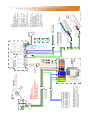
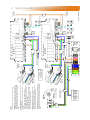
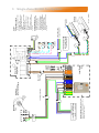
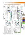
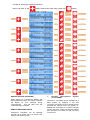
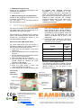
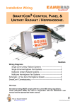
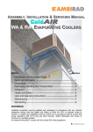
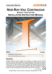
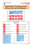
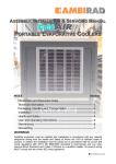
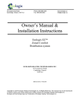
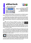
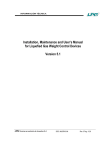
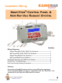
Installation Wiring
SmartCom 3
SMARTCOM 3 CONTROL PANEL &
NOR-RAY-VAC RADIANT SYSTEM.
Section
Wiring Diagrams
Single Zone B80, B160, B300 Fan Systems------------------------- 1
Split-zone B80, B160, B300 Fan Systems --------------------------- 2
Single Zone BH300 Fan Systems -------------------------------------- 3
Split-zone BH300 Fan Systems ----------------------------------------- 4
Schematic Nor-Ray-Vac Multi-zone System ----------------------------- 5
SmartCom³ Commissioning -------------------------------------------------- 6
End Vent Suction Setting Procedure --------------------------------------- 7
Warnings
All external wiring MUST comply with the current IEE wiring regulations.
These instruction MUST be used in conjunction with the SmartCom³ user
manual and the Nor-Ray-Vac O&M instruction manual.
Visit our Support Database
at www.s-i-d.co.uk
4-Core Armoured or
Screened Cable 1.5mm²
MPORTANT
For Inverter panels only
(fan types B80 / B160 & B300):
MAXIMUM length of cable between inverter
and fan is 5m (EMC class A building) or
10m (EMC class B building).
N.B. if in doubt, do not exceed 5m.
230V 1P 22A
230V 1P 22A
230V 1P 30A
B80
B160
B300
THE LOCAL RELAY UNIT houses an inverter. This
converts the 230V single-phase input into a
three-phase 230V output. The inverter provides a
soft start to the motor, which extends the motor life
by minimising the start current.
ELECTRICAL INPUT
FAN TYPE
SUPPLY VIA ISOLATOR
3 Phase
Isolator
L
L
N N
U
(FAN CIRCUIT)
2
40
9
3
4
Volt free
Fan Trip
Indication
by others
C
Inverter
Local Relay
Unit
V W 1
Low Voltage
+15V DC
!
41
(FAN CIRCUIT)
5
6
!
LIVE
NEUT
1/L 2/N
(LIVE)
SmartCom
Singlezone
(NEUTRAL)
FAN MOTOR
230V 3-Phase Supply.
Motor must be wired DELTA
10
eg Door
Drawing No. : 900287 R5
Burners
Zone A
Supply to inline
burners
*The power supply is non-isolated,
therefore all wiring to the control must be
mains rated.
REMOTE SENSOR(s) may be
placed at a max distance of 100m
from the control unit, using
screened 6A mains* cable.
Wiring should be kept separate
from mains wiring to minimise
noise pick up. Set within Engineers
functions for remote sensor.
*The power supply is non-isolated,
therefore all wiring to the control must be
mains rated.
REMOTE SWITCH INPUTS
should be connected by 6A mains
Max length is 100m.
Low voltage switching inputs to be
normally open (closed circuit to
enable).
Connect to B0 & B1 for remote ON
(ie BMS time control).
Connect to B0 & B2 for remote
OFF (ie door interlock. remote
frost etc).
NOTES:
230V 50Hz 1 Pha
Supply via Isolator
Black Bulb
Sensor
Note: Connection to the
burners MUST be made
via a 3A fused spur.
(where applicable)
Remote ON
eg B.M.S.
(where applicable)
Remote OFF
B1 B0 B2 S/R0 S/R1
(COMMON)
FUSE RATING
!
(REMOTE ON)
Exhaust
Fan
(REMOTE OFF)
1
Single Zone B80, B160, B300 Fan Systems.
(HEAT 1 OUTPUT)
3 Phase
Isolator
230V 1P 22A
230V 1P 22A
230V 1P 30A
B80
B160
B300
FAN TYPE ELECTRICAL INPUT
SUPPLY VIA ISOLATOR
4-Core Armoured or
Screened Cable 1.5mm²
FAN MOTOR
230V 3-Phase Supply.
Motor must be wired DELTA
Exhaust
Fan
Burners
Zone B
Burners
Zone A
Supply to inline
burners
THE LOCAL RELAY UNIT houses an inverter. This converts the 230V
single-phase input into a three-phase 230V output. The inverter provides a
soft start to the motor, which extends the motor life by minimising the start
current.
REMOTE SENSOR(s) may be placed at a max distance of 100m
from the control unit, using screened 0.75mm² cable.
Wiring should be kept separate from mains wiring to minimise noise
pick up. Set within Engineers functions for remote sensor.
REMOTE SWITCH INPUTS should be connected by 0.75mm² cable.
Max length is 100m.
Low voltage switching inputs to be normally open (closed circuit
Supply to inline
to enable).
burners
Connect to B0 & B1 for remote ON (ie BMS time control).
Connect to B0 & B2 for remote OFF (ie door interlock. remote frost etc).
For Master/Slave networks, remote OFF can be set for individual
zones or total system via the Master.
If individual BMS ON/OFF on master/slaves systems are required,
set all SmartCom programs to 24 hour and use normally closed
contacts across B0 and B2. Set engineers variable.
NETWORK. Master-slave (Network) communication is by screened
twisted pair cable, RS485 compatible such as Belden 9841. Maximum
overall system length of 500m. Connect screen to C0. NOTE: Diagram
shows a master and ONE slave configuration**. Wire further slaves in
parallel.
L
Note: Connection to the
burners MUST be made
via a 3A fused spur.
N N
Burners
Zone A
L
41
U
V W 1
41
230V 50Hz 1 Pha
Supply via Isolator
Burners
Zone B
2
40
40
8
C
9
25
14
5
6
3
7
C
9
25
14
4
Low Voltage +15V DC
230V 50Hz 1 Pha
Supply via Isolator
8
(Master)
6
LIVE
10
!
1/L 2/N
10
Fan Trip
Indication
by others
!
eg Door
To other slave
controllers
(where applicable)
Drawing No.: 900288 R5
(where applicable)
(where applicable)
eg Door
Remote OFF
Remote ON
eg B.M.S.
Black Bulb
Sensor
To other slave
controllers
Remote OFF
S/R0S/R1 D0 D1 O0 O1 B1 B0 B2 C2 C0 C1 66 64 20
Black Bulb
Sensor
S/R0S/R1 D0 D1 O0 O1 B1 B0 B2 C2 C0 C1 66 64 20
! FUSE RATING
1/L 2/N
! FUSE RATING
Volt Free Circuit
NEUT
LIVE
NEUT
Inverter
Local
Relay
Unit
5
SmartCom Mulitizone
7
(Slave 1)
SmartCom Mulitizone
(COMMON)
(COMMON)
Controls cables min 0.75mm² cable for up to a distance of 200m.
(REMOTE ON)
NOTES:
(REMOTE OFF)
(REMOTE OFF)
2
Split-zone B80, B160, B300 Fan System.
415V 3P 25A
BH300
FAN MOTOR
415V 3-Phase Supply.
Motor must be wired DELTA
!
U
2
40
(FAN CIRCUIT)
(FAN CIRCUIT)
9
3
4
Volt free
Fan Trip
Indication
by others
C
Local Relay
Unit
1
41
5
6
!
1/L 2/N
(LIVE)
LIVE
(NEUTRAL)
NEUT
10
eg Door
Drawing No. : 900289 R7
Burners
Zone A
Supply to inline
burners
*The power supply is non-isolated,
therefore all wiring to the control must be
mains rated.
REMOTE SENSOR(s) may be
placed at a max distance of 100m
from the control unit, using
screened 6A mains* cable.
Wiring should be kept separate
from mains wiring to minimise
noise pick up. Set within Engineers
functions for remote sensor.
*The power supply is non-isolated,
therefore all wiring to the control must be
mains rated.
REMOTE SWITCH INPUTS
should be connected by 6A mains
Max length is 100m.
Low voltage switching inputs to be
normally open (closed circuit to
enable).
Connect to B0 & B1 for remote ON
(ie BMS time control).
Connect to B0 & B2 for remote
OFF (ie door interlock. remote
frost etc).
NOTES:
230V 50Hz 1 Pha
Supply via Isolator
Black Bulb
Sensor
Note: Connection to the
burners MUST be made
via a 3A fused spur.
(where applicable)
Remote ON
eg B.M.S.
(where applicable)
Remote OFF
B1 B0 B2 S/R0S/R1
(COMMON)
FUSE RATING
!
(REMOTE ON)
SmartCom
Singlezone
V W
Mains Voltage
230V AC
L3 L2 L1 L1 N N
4-Core Armoured Cable
THE LOCAL RELAY UNIT houses a 3pha
motor contactor and overload plus any
additional fan logic circuitry.
ELECTRICAL INPUT
FAN TYPE
SUPPLY VIA ISOLATOR
3 Phase
Isolator
Exhaust
Fan
(REMOTE OFF)
3
Single Zone BH300 Fan System.
(HEAT 1 OUTPUT)
3 Phase
Isolator
ELECTRICAL INPUT
415V 3P 25A
BH300
Burners
Zone A
Supply to inline
burners
Burners
Zone B
FAN TYPE
SUPPLY VIA ISOLATOR
4-Core Armoured Cable
FAN MOTOR
230V 3-Phase Supply.
Motor must be wired DELTA
Exhaust
Fan
THE LOCAL RELAY UNIT houses an inverter. This converts the 230V
single-phase input into a three-phase 230V output. The inverter provides a
soft start to the motor, which extends the motor life by minimising the start
current.
REMOTE SENSOR(s) may be placed at a max distance of 100m
from the control unit, using screened 0.75mm² cable.
Wiring should be kept separate from mains wiring to minimise noise
pick up. Set within Engineers functions for remote sensor.
REMOTE SWITCH INPUTS should be connected by 0.75mm² cable.
Max length is 100m.
Low voltage switching inputs to be normally open (closed circuit
Supply to inline
to enable).
burners
Connect to B0 & B1 for remote ON (ie BMS time control).
Connect to B0 & B2 for remote OFF (ie door interlock. remote frost etc).
For Master/Slave networks, remote OFF can be set for individual
zones or total system via the Master.
If individual BMS ON/OFF on master/slaves systems are required,
set all SmartCom programs to 24 hour and use normally closed
contacts across B0 and B2. Set engineers variable.
NETWORK. Master-slave (Network) communication is by screened
twisted pair cable, RS485 compatible such as Belden 9841. Maximum
overall system length of 500m. Connect screen to C0. NOTE: Diagram
shows a master and ONE slave configuration**. Wire further slaves in
parallel.
Burners
Zone A
L3 L2 L1 L1 N N
Note: Connection to the
burners MUST be made
via a 3A fused spur.
41
U
V W
1
41
230V 50Hz 1 Pha
Supply via Isolator
Burners
Zone B
2
40
40
8
C
9
25
14
5
6
3
7
C
9
25
14
5
4
Mains Voltage 230V AC
230V 50Hz 1 Pha
Supply via Isolator
8
(Master)
LIVE
!
(where applicable)
1/L 2/N
10
Fan Trip
Indication
by others
!
eg Door
To other slave
controllers
(where applicable)
Drawing No.: 900290 R7
(where applicable)
(where applicable)
eg Door
Remote OFF
Remote ON
eg B.M.S.
Black Bulb
Sensor
To other slave
controllers
Remote OFF
S/R0S/R1 D0 D1 O0 O1 B1 B0 B2 C2 C0 C1 66 64 20
Black Bulb
Sensor
S/R0S/R1 D0 D1 O0 O1 B1 B0 B2 C2 C0 C1 66 64 20
Remote ON
10
! FUSE RATING
1/L 2/N
! FUSE RATING
Volt Free Circuit
NEUT
LIVE
NEUT
Local
Relay
Unit
6
SmartCom Mulitizone
7
(Slave 1)
SmartCom Mulitizone
(COMMON)
(COMMON)
Controls cables min 0.75mm² cable for up to a distance of 200m.
(REMOTE ON)
NOTES:
(REMOTE OFF)
(REMOTE OFF)
4
Split-zone BH300 Fan System.
From ‘Power out’ on
End Vent Burner to
In-line Burners
In-line Burner
Fused Spur
In-line Burner
Fused Spur
From ‘Power out’ on End Vent
Burner to In-line Burners
End Vent
Burner
End Vent
Module
For ease and swiftness of initial start-up, the
SmartCom³ range of electronic controllers is
supplied factory pre-set to operate a standard
warm air unit heater. To operate with a
Nor-Ray-Vac system however, the parameters
will have to be changed via the engineers
End Vent
Burner
230V 50Hz 13A
Mains Supply
End Vent
Module
SmartCom³ no.1
‘Master’ (SC3-MZ)
Isolator
0.75mm²
Screened
Cable
Sensor
Zone 1
1st Branch Zone 1
In-line Burner
Fused Spur
From ‘Power out’
on End Vent Burner
to In-line Burners
To ‘Mains In’ on
End Vent Burner
Fused Spur
To ‘Mains In’ on
End Vent Burner
End Vent
Module
End Vent
Burner
Fused Spur
In-line Burner
Isolator
Networking Cable
Screened pair Beldon
9841 or equiv
Local Relay
Unit / Inverter
Panel
* 4 core
Armoured Cable
0.75mm²
Screened
Sensor
Zone 2
* IMPORTANT
For Inverter Panels only
(fan types B80/B160 & B300)
MAXIMUM length of cable between
Inverter and Fan is 5m.
SmartCom³ no.2
‘Slave’ (SC3-MZ)
230V 50Hz 13A
Mains Supply
IMPORTANT
Fan types B80/B160 & B300)
MOTOR MUST BE WIRED IN
DELTA.
Tail Pipe
1st Branch Zone 2
In-line Burner
Isolator
SmartCom³ Commissioning.
2nd Branch Zone 1
6
Fused
Spur
Schematic Nor-Ray-Vac Multizone System.
Fused Spur
5
settings.
Follow the step by step instructions overleaf for
the correct settings. For more detailed
instructions and other engineer settings, refer to
the
SmartCom³
user
manual
GB/
SCOM/120/0309.
In order to access the engineer functions:
Press and hold in the
button and at the same time, press the
CONTROL TYPE
SET/OK
ARM A I R
press
to alter
or press
to advance
CONTROL TYPE
RAD I ANT
SET/OK
press
to accept.
Press
to advance
RAD/NRV/HB SPL I T
OFF
SET/OK
press
to alter
or press
to advance
RAD/NRV/HB SPL I T
ON
SET/OK
press
to accept.
Press
to advance
I NTERNAL SENSOR
SET/OK
ON
press
to alter
or press
to advance
I NTERNAL SENSOR
SET/OK
OFF
press
to accept.
Press
to advance
EXTERNAL SENSOR
SET/OK
OFF
press
to alter
or press
to advance
EXTERNAL SENSOR
SET/OK
ON
press
to accept.
Press
to advance
NETWORKING
OFF
SET/OK
press
to alter
or press
to advance
NETWORKING
ON
SET/OK
press
to accept.
Press
to advance
MASTER UN I T
OFF
SET/OK
press
to alter
or press
to advance
MASTER UN I T
ON
SET/OK
press
to accept.
Press
to advance
SLAVE UN I T
0
SET/OK
press
to alter
or press
to advance
SLAVE UN I T
3
SET/OK
press
to accept.
Press
to advance
SLAVE TOTAL
0
SET/OK
press
to alter
or press
to advance
SLAVE TOTAL
6
SET/OK
press
to accept.
Press
to advance
M
press
press
once.
once for
split zonal
systems
press
press
press
press
press
press
press
once to
turn off
internal
once to
turn off
external
once for
master
slave
once if
master
unit
for unique
slave
number
for total
no. of
slaves
button.
MASTER & SLAVE (NETWORK)
When setting up a SmartCom³ Master and
Slave (Network) system, the master controller
will display an error message during
commissioning.
This will clear once the
commissioning is complete.
REMOTE SWITCHED INPUTS
SmartCom³ controllers can be operated
remotely via a remote ON or a remote OFF
signal in the following ways:
A.
Building
Management
Control (BMS).
System
SmartCom³ controllers can be operated via a
BMS system, by applying a volt free
connection (ie closed circuit to enable) across
terminals B1 and B0 turns the system on.
Making this connection on a master controller
will turn the entire system on whereas making
this connection on a slave unit will only bring
on that zone.
1. BMS controlling time only.
Ensure all the programmed ON times in the
SmartCom² are turned off
(i.e. They read “- -:- -”).
2. BMS controlling time and temperature.
Ensure all the programmed ON times in the
SmartCom² are turned off
(i.e. They read “- -:- -”). Set all the required
day temperatures to 30°C.
End Vent Suction Setting Procedure.
The use of an inverter on the B80, B160, B300
fan system allows the end vent suction to be
adjusted by varying the fan speed.
The description for adjusting the fan speed is
given in the following section. Apart from this
change the commissioning section in the
manual should be followed.
End vent suction (B80, B160, B300 )
For these systems the end vent suction is
adjusted by altering the low speed setting of
the inverter within the local relay unit.
1. Check that the fan damper is fully open
and secure.
2. Ensure the SmartCom³ is in a programmed
ON time.
3. Set the required room temperature above
the actual room temperature.
4. After a 30s delay the fan should run.
5. The fan should now be running and the
inverter should be showing the motor
frequency in the display.
6. Check for correct rotation of fan.
7. Press the mode button 3 times until
‘COnF’ appears on the display.
8. Press the jog dial to enter. Rotate jog dial
The inverter
interface
(door open)
Mode LEDs
until ‘LSP’ is displayed. Press jog dial to
enter. Rotate jog dial to adjust frequency.
Press jog dial to enter new value, causing
the inverter to change its speed. Adjust the
frequency until the appropriate end vent
suction is achieved, this is given in the
table below.
9. Pressing the ESC button twice will return
the inverter to the ’rdY’ display. The setting
procedure is now complete.
System
End vent
pressure
mbar
Standard systems
6.25
Single 32LR End vent only
7.5
Single 38LR End vent only
8.25
Single 46LR End vent only
9.25
Three 46LR in a single branch
5.6
End vent suction (BH300 ONLY)
This unit does not feature an inverter, the end
vent suction adjustment is made using the fan
damper, details of this are given in the
Nor-Ray-Vac manual.
Mode button:
Switches between control/
programming modes.
(Only accessible with door
open).
7 segment display
Jog dial:
For navigation when
turned clockwise or
anticlockwise, or
selection/validation
when pressed.
Escape button:
Exits a menu or
parameter.
The local relay unit
AmbiRad Limited Fens Pool Avenue
Brierley Hill West Midlands DY5 1QA
United Kingdom.
Telephone 01384 489700
Facsimile 01384 489707
Email [email protected]
Website www.ambirad.co.uk
Technical Suport www.s-i-d.co.uk
AmbiRad is a registered trademark of AmbiRad Limited. Because of continuous product
innovation, AmbiRad reserve the right to change product specification without due notice
Document reference number GB/CON/004/0212
7
B. Remote door interlock. SmartCom³
controllers can be connected to a door
interlock, remote frost stat or permanent off
switch via terminals B2 and B0. When a volt
free connection is provided (ie closed circuit to
enable) at these terminals, the controller
reverts to FROST ONLY mode. Refer to the
individual wiring diagrams for wiring
configurations and type.