1
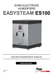
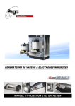
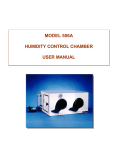
IMMERSED ELECTRODES
HUMIDIFIERS
EASYSTEAM
ES3-M-OEM
Use and Maintenance Manual
READ AND KEEP
USER MANUAL
REV. 01-09 ITA
Thank you for choosing a sunk-electrode EASYSTEAM humidifier
Read this manual carefully: doing so will ensure that installation is carried out correctly and that the
machine is used properly and efficiently.
You are therefore advised to store the manual near the humidifier so that it can be consulted for
maintenance and/or modification purposes as and when necessary..
To aid comprehension the manual contains the following symbols:
Note to be read carefully.
Indicates procedures that must be followed with due care and attention so as to prevent
damage to the humidifier, injury or malfunctions
Indicates forbidden practices and procedures which could cause damage to the humidifier,
injury or malfunctions.
Useful tip.
Indicates that the customer service centre should be contacted.
Pag. 2
MANUALE D’USO – USER MANUAL
CONTENTS
INTRODUZIONE
Page.
Page.
Page.
Page.
Page.
Page.
4
5
7
7
8
8
1.1
1.2
1.3
1.4
1.5
1.6
General
Operating principle
OEM series humidifier ID codes
OEM series humidifier technical data
Overall dimensions
ID data
PROGRAMMING
Page. 9
Page. 10
2.1
2.2
SLIM controller description
Level 1 programming
SWITCHING ON
Page. 11
Page. 11
3.1
3.2
Initial start-up
Steam production
MAINTENANCE
Page. 12
Page. 12
Page. 12
Page. 13
Page. 15
4.1
4.2
4.3
4.4
4.5
Maintenance
General safety rules
Maintenance Intervals
Changing the cylinder
Cleaning the cylinder
APPENDICES
Page. 15
5.1
CAP. 1
CAP. 2
CAP. 3
CAP. 4
CAP. 5
OEM series Spare parts list
MANUALE D’USO – USER MANUAL
Pag. 3
CHAP.1 INTRODUCTION
1.1
GENERAL
EASYSTEAM sunk-electrode humidifiers are the latest family of humidifiers to be released onto
the market: they are characterised by outstanding completeness of performance and extremely
simple maintenance
EASYSTEAM humidifiers feature software with an extensive programming range, full
personalisation and completely automatic operation
This means that the user can set steam output to maximum or some intermediate percentage,
regulate de-concentration emptying frequency or have all the water emptied automatically when the
machine has been idle for a set time.
The EASYSTEAM line also features a display that shows real-time room humidity, the current
being absorbed by the electrodes, working hours, various warnings/alarms, water filling/emptying
status and a full range of user-friendly programming parameters.
EASYSTEAM humidifiers also incorporate a buzzer to warn the user of any faults; the internal
software evaluates the seriousness of the problems and shuts down or continues steam generation
accordingly.
A key advantage of the EASYSTEAM range is that the cylinder with the stainless steel electrodes is
easily changed when normal wear makes such replacement necessary.
Pag. 4
MANUALE D’USO – USER MANUAL
1.2
OPERATING PRINCIPLE
The sunk-electrode humidifiers in the EASYSTEAM range use the conductivity of potable water to
produce steam by boiling.
The cylinder electrodes are sunk in the water: a current is generated between the electrodes and this
heats the water to boiling point.
Current intensity (expressed in amperes) varies according to the quantity of in-cylinder water that is
in contact with the electrode surfaces and the conductivity of the water.
The electronic controller measures, via an amperometric transformer, current intensity and controls
the water inlet valve (to raise the water level) or the discharge valve (to lower it) accordingly. This
system is fully automatic.
Combined use of the microprocessor and a humidity sensor also makes it possible to effect
proportional control: this optimises water and electricity consumption according to required
humidity levels.
In addition to ensuring that the humidifier works properly the discharge pump also empties the
cylinder completely when the unit had been idle for a set time: this prevents lime scale or other
particles created during the boiling process from depositing.
The humidifiers in the EASYSTEAM range are fully automatic and require only replacement of the
cylinder when the electrodes are worn.
The diagram below illustrates the operating cycle.
MANUALE D’USO – USER MANUAL
Pag. 5
The supplied steam is managed proportionally to steam production request that the electronic
control computes on the basis of functioning selected between the available five described at
chap.2.2. The minimum steam
supply is fixed at 20% and it is
Supplied steam
managed by an activation
hysteresis;
the
maximum
Maximum supply
supply obtained with the
maximum steam production
request, corresponds to first
level variable set percentage
(Pr). For example if the steam
production percentage Pr, on
ES3 humidifier that produces
3Kg/h of steam, is set to 100%,
Minimum supply
the maximum supply will be
3Kg/h; but if Pr=50 the
maximum supply will be
1,5Kg/h
Steam production request
To ensure proper humidifier performance use only mains drinking water; this is because it
is free from any harmful content and is compatible with the conductivity range needed for
optimal humidifier performance. Note that in some areas mains water may be unsuitable for optimal
performance owing to very low conductivity or very hard or too much aggressive; the following
table summarizes the parameters required for correct humidifier operation..
WATER SUPPLY OPERATING RANGE
PARAMETER
UNIT OF MEASURE
* Conductivity of water at 20° C
µS/cm
Hardness
mg/l CaCO3
Chlorine
mg/l Cl
Chlorides
ppm Cl
Calcium sulphate
mg/l CaSO4
Metalline impurities / Solvents / Soaps / Lubricants
mg/l
Temperature
°C
LIMITS
MIN MAX
250
1300
160
450
0
0,2
0
25
0
95
0
0
+1
+40
* Stated conductivity refers to water at 20° C; bear in mind that conductivity diminishes as water
temperature falls and so water may not be very conductive in winter when mains water is
particularly cold.
To avoid this inconvenience, diminish the produced steam percentage described in chapter
3 PROGRAMMING of this manual.
Do not fill the humidifier with water from wells or water that has been treated with
softening purifiers.
Pag. 6
MANUALE D’USO – USER MANUAL
OEM SERIES HUMIDIFIER ID CODES
1.3
ES3-M-OEM
1.4
single-phase custom humidifier complete with electronic kit with steam
output capacity of 3 Kg/h, proportional operation with 0-10 V signal.
OEM SERIES HUMIDIFIERS TECHNICAL DATA
TECHNICAL DATA and
OPERATING CONDITIONS
STEAM PRODUCTION (Kg/h)
ELECTRICAL POWER SUPPLY
POWER (KW)
ABSORBED CURRENT (A)
TYPE OF CONTROL
ELECTRONIC CONTROL POWER
SUPPLY
STEAM OUTLET DIAMETER (mm)
NUMBER OF CYLINDERS
WEIGHT (EMPTY) (Kg)
WEIGHT OF WORKING UNIT (Kg)
WATER SUPPLY PRESSURE
WORKING AMBIENT TEMPERATURE
WORKING AMBIENT HUMIDITY
STORAGE TEMPERATURE
PROTECTION RATING
AMBIENT TEMPERATURE OF
ELECTRONIC CONTROL OPERATION
AMBIENT HUMIDITY OF ELECTRONIC
CONTROL OPERATION
ELECTRONIC CONTROL PROTECTION
RATING
ES3-M-OEM
3
230V 50-60HZ
2
9
SLIM EASYSTEAM
230V 50-60HZ
25
1
6
8
1-10 bar
+1 ÷ +50 °C
< 60 %RH (90 %RH non condensing)
-10 ÷ +70 °C
IP00
+0 ÷ +60 °C
< 60 %RH (90 %RH non condensing)
IP20
MANUALE D’USO – USER MANUAL
Pag. 7
OVERALL DIMENSIONS
1.5
OEM SERIES
H
L
P
STEAM GENERATING UNIT
TYPE
ES3-M OEM
L
P
H
340
210
380
ELECTRONIC KIT
Measurements in mm.
IDENTIFICATION DATA
1.6
The unit described in this manual has, on its side, an ID plate showing all the relevant identification
data:
• Name of Manufacturer
• Unit model
• Serial number
• Power supply voltage
• Rated current
Pag. 8
MANUALE D’USO – USER MANUAL
CAP. 2 PROGRAMMAZIONE
DESCRIPTION OF SLIM CONTROLLER
2.1
1. The SLIM CONTROLLER is the control unit on the front of the humidifier. It consists of an 8LED display to visually check values (fig. 25) and 6 keys to adjust display and modify settings (fig.
26).
Relative humidity %
visualization
Steam being produced
Current absorbed (A)
visualization
Steam output %
visualization
Water inlet
Display
On = Water drain
Blinking = Water drain test
Alarm
Fig. 25
Used to display absorbed current or
steam production (%)
UP key, alarm mute
ON/OFF
Stand-by key
SET key
DOWN key
Manual water
emptying
Fig. 26
MANUALE D’USO – USER MANUAL
Pag. 9
LEVEL 1 PROGRAMMING
2.2
1. Level 1 programming allows the user to modify the steam production percentage Pr.
VAR.
MEANING
Pr
Steam production percentage
Bp
Not used
StC
r0
UrC
Not used
Not used
Not used
VALUES
DEFAULT
all models
20 ÷ 100 %
70 %
The steam percentage value Pr is the value the humidifier is able to reach at maximum
output. For example, leaving the setting at 100% on an ES3 rated at 3 Kg/h will give 3
Kg/h of steam output; if the Pr setting is reduced to 50% the humidifier will produce 1,5 Kg/h at
most.
The Pr variable is highly useful where water conductivity is poor and when you need to
make the most of the cylinder when it is nearing replacement; for further information
consult chapter 5 TROUBLESHOOTING of this manual.
To gain access to the Level 1 programming menu proceed as follows:
- Press the (t) and (u) keys simultaneously and keep them pressed for a few seconds until the
first programming variable appears on the display.
- Release the (t) and (u) keys.
- Select the variable to be modified using the (t) or (u) key.
- When the variable has been selected it is possible:
- to display the setting by pressing SET
- to modify the setting by pressing the SET key and the(t) or (u) keys.
- When configuration values have been set you can exit the menu by pressing the (t) and (u)
keys simultaneously for a few seconds until the parameter shown before programming was
accessed (e.g. steam production or absorbed current) reappears.
The new settings are saved automatically when you exit the configuration menu.
.
Pag. 10
MANUALE D’USO – USER MANUAL
CAP. 3 SWITCHING ON THE HUMIDIFIER
INITIAL START-UP
3.1
1. Check that default setting is compatible with signal connection.
1. Before powering up the humidifier check for correct connection of phases and signal
type; check for correct connection of the water mains, excess water discharge and steam pipes.
If the mains water feed line consists of piping that might contain oily residues or other foamgenerating substances it is essential that it be washed out by letting water flow through for
several minutes.
2. To verify the absence of water loss internally the humidifier
3. Power up the humidifier.
4. The humidifier will carry out a water discharge for several seconds as it emits a prolonged beep.
5. At this point the humidifier is in STAND-BY mode; to switch it on press the ON/OFF –
STAND-BY key: current absorption is displayed.
6. To function correctly humidifier needs enabling at digital input 1 with a free-voltage contact
(terminal blocks 1 and 2 on 100 Master card) indifferently from selected functioning mode.
If enabling is missing, the display will show OFF alternate to normal visualization.
STEAM PRODUCTION
3.2
1. Set the enable.
2. Let the cylinder fill until the water starts to boil; empty the cylinder completely using the
MANUAL DISCHARGE key to prime the pump and repeat the procedure once or twice.
3. At this point the humidifier is operative and will work autonomously
MANUALE D’USO – USER MANUAL
Pag. 11
CAP. 4 MAINTENANCE
MAINTENANCE
4.1
To ensure working safety, correct functioning and an optimal output of EASYSTEAM humidifiers,
it is necessary to execute maintenance operations according to following instructions.
GENERAL SAFETY RULES
4.2
Every type of maintenance has to be done exclusively by experienced and qualified
technical staff, conscious about necessary safety.
Before starting any maintenance procedure, to proceed as follows:
1. If unit is out of service because of an alarm condition, to note the displayed error code.
2. To close the valve of water supply.
3. To put the humidifier in stand-by using the proper key and discharge completely the water
contained in the cylinder using the key “Manual water emptying” on Slim Controller (see chap.
3).
4. To disconnect the unit from the electric system sectioning the power input permanently
padlocking it on OFF.
5. To wait the cylinder and the humidifier have cooled or to use protection gloves.
6. Each unit element, if it is defective, has to be replaced exclusively with original spare parts.
MAINTENANCE INTERVALS
4.3
Following are indicated the maintenance operations to execute and their suggested frequency.
Being electrodes consumption and incrustations and solid deposits formation into the cylinder
variables according to the type of water (also with the same conductivity), it could be necessary to
modify these intervals.
To verify this need checking the deposits quantity into the cylinder; a quickly accumulation of
incrustations and deposits requires to increase the suggested maintenance frequency and/or the deconcentration discharges parameters variation.
To minimize residual formation on the bottom of cylinder it’s advisable to increase
deconcentration drain frequency reducing value of S2 parameter. This trick has
disadvantage of bigger water and energy consumption.
Pag. 12
MANUALE D’USO – USER MANUAL
MAINTENANCE INTERVENTION
FREQUENCY
To verify there are not water losses internally the humidifier.
after 1 hour of working
To verify electrical connections clamping.
after 4 weeks of working
To verify there are not water losses internally the humidifier.
monthly or every
To verify the cylinder state, to remove incrustations and deposits if
500 hours of working
present.
To replace the cylinder if necessary.
To verify cylinder electrodes consumption and the absence of
quarterly or every
deformations or darkening on their surface; to replace the cylinder if
1000 hours of working
worn and torn and if it shows manifest faults.
To replace the cylinder.
yearly or every
To verify electrical connections clamping and water and steam
2500 hours of working
connections good state.
To verify there are not water losses internally the humidifier.
To verify cylinder state, to verify electrodes consumption, to remove
with alarm code E1
incrustations and deposits if present and to replace the cylinder if
necessary.
To verify there are not water losses internally the humidifier.
with alarm code E3
To verify that the solenoid valve is not disconnected or broken and to
replace it if necessary.
To verify that the drain pump is not disconnected or broken and to
replace it if necessary.
with alarm code E5 or E6
If present to remove incidental obstructions on cylinder bottom and/or
in draining pipes.
4.4
CHANGING THE CYLINDER
The only part of the humidifier subject to wear is the electrode cylinder. This wears
according to how much the machine is used or it is not possible to remove the internal
incrustations.
The EASYSTEAM range features stainless steel electrodes to maximise durability: however,
durability will largely depend on the quality of the water (conductivity and hardness) and on how
much the machine is used.
When the electrodes are worn the water level will rise excessively and trip the maximum level
alarm E1 several times: the cylinder must, at this point, be replaced.
Once you have checked that this alarm does not have other causes (see Chap. 6 – Troubleshooting)
change the cylinder. Proceed as follows:
NEVER CHANGE THE CYLINDER WITH THE MACHINE HOT AND WITH
WATER INSIDE IT. EMPTY ALL THE WATER FROM THE CYLINDER USING
THE MANUAL DISCHARGE KEY FIRST! IT IS COMPULSORY TO FOLLOW
THE INSTRUCTIONS REPORTED AT CHAPTER 6.2.
MANUALE D’USO – USER MANUAL
Pag. 13
1. Insert the new cylinder by repeating the above procedure in reverse order; check that the new
cartridge has the 2 supplied O-rings and that they are positioned correctly.
If necessary to use on O-rings and flanges the lubricating issued with the humidifier for making
their insertion easier (fig. 35 and 36).
Fig. 35
Fig. 36
2. Flush the cylinder completely 2 – 3 times immediately after replacement: do this by pressing the
“manual empty” key
3. To verify there are not water losses internally the humidifier after 1 hour of working from
cylinder replacing.
If there is a power supply failure during cylinder replacement empty the cylinder by
detaching the filling hose from the relevant solenoid valve (fig. 37).
Fig. 37
Pag. 14
MANUALE D’USO – USER MANUAL
4.5
CLEANING THR CYLINDER
When presence of incrustations and deposits into the cylinder prevents an adequate
passage of current between electrodes or thwarts the water discharge, it is necessary a
cleaning operation of cylinder.
NEVER CHANGE THE CYLINDER WITH THE MACHINE HOT AND WITH
WATER INSIDE IT. EMPTY ALL THE WATER FROM THE CYLINDER USING
THE MANUAL DISCHARGE KEY FIRST! IT IS COMPULSORY TO FOLLOW
THE INSTRUCTIONS REPORTED AT CHAPTER 6.2
1. Remove the cylinder from humidifier
2. Utilizing the hole on upper side of cylinder, to clean and remove the incrustations on the
electrodes and on accessible parts with a mechanical action using a plastic spatula and running
water or with a solution of water and 20% acetic acid (fig. 38). Execute the same operation on
slits of lower filter (fig. 39). During clearing operations do not damage or scrape coupling parts
that assure hydraulic seal as O-ring housing or flanges’ entrance. During clearing operations do
not wet the connector or cables holder ring UM-CA-01 (fig. 40).
Fig. 38
Fig. 39
Fig. 40
3. Clean and control the two O-ring integrity, replace them if necessary and verify their correct
positioning in the two predisposed housings on cylinder. Insert the cylinder by repeating the
above procedure in reverse order and verify its correct positioning. In coupling use the
lubricating issued with the humidifier for making readjustment operations easier.
4. Flush the cylinder completely 2 – 3 times immediately after replacement: do this by pressing the
“manual empty” key.
5. To verify there are not water losses internally the humidifier after 1 hour of working from
cylinder replacing.
MANUALE D’USO – USER MANUAL
Pag. 15
CAP. 5 APPENDICES
OEM SERIES EXPLODED VIEW
5.1
1A
14
15
16
Pag. 16
MANUALE D’USO – USER MANUAL
OEM SERIES SPARE PARTS LIST
Rif
Code
Description
1
1A
2
3
4
4+5
6
7
8
9
10
11
12
13
14
15
16
UMICO25
UMICO25
400UMCL04
UMIMOLLA4
UMISIFONE1
400UMSIF04
UMITUBO10-2
UMILAMCUST
400UM931OEM
UMIVALV1
UMIMAN12
UMIGOM12
UMIPORTGOM12
UMIOR1
UMICURVA90°
DN25 steam output flange
DN25 steam output flange
Electrodes cylinder for ES3-M-OEM
Cylinder fixing spring for ES3-M-OEM
Water drain siphon (exceeding water or deconcentration drain)
Complete siphon kit + water drain pipes for ES3-M-OEM
Tap water inlet pipe (L=1250mm)
aisi 316 stainless steel sheet panel bracket
230V 50/60 Hz asyncronous drain pump
230V 50/60 Hz solenoid valve for water filling
Solenoid fixing screws
Pump fixing screws
DN25 hose for water drain
½ gas elbow
½ gas hose bracket
O-Ring diameter 88,49 X 3,53 SILICON 60Sh.
24mm joint elbow 90°
Request spare parts from your dealer.
MANUALE D’USO – USER MANUAL
Pag. 17
Pag. 18
MANUALE D’USO – USER MANUAL