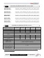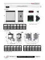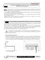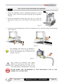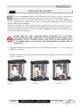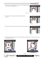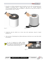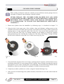
1
SUNK-ELECTRODE
HUMIDIFIERS
EASYSTEAM
Use and maintenance manual
READ AND KEEP
REV. 04‐10
ENG
Thank you for having chosen a PEGO EASYSTEAM sunk-electrode humidifier.
Reading this manual in full will enable you to correctly install the machine and make better use of
it.
It is therefore advised to keep this manual near the humidifier for eventual maintenance operations
and functioning amendments.
How to read the manual.
Graphic indications with the following meanings have been inserted to facilitate reading:
Indicates a note requiring careful reading.
Indicates the operations to be scrupulously performed to avoid damaging the humidifier,
injuring persons or any malfunctionings.
Indicates the operations not to be performed to avoid damaging the humidifier, injuring
persons or any malfunctionings.
Indicates a suggestion.
Indicates to contact the PEGO 2 HUMIDIFIERS DIVISION after-sales assistance centre
reported at the back of this manual.
Page 2
MANUALE D’USO – USER MANUAL
Rev. 04-10
TABLE OF CONTENTS
INTRODUCTION
Page 5
Page 6
Page 7
Page 9
Page 9
Page 10
Page 10
Page 11
Page 12
Page 12
1.1
1.2
1.3
1.4
1.5
1.6
1.7
1.8
1.9
1.10
Generality
Warranty conditions
Functioning principle
ES Series humidifiers identification codes
ES Series humidifiers technical data
OEM Series humidifiers identification codes
OEM Series humidifiers technical data
Overall dimensions
Identification data
Standard equipment
INSTALLATION
Page 13
Page 15
Page 19
Page 19
Page 24
Page 25
Page 25
Page 25
Page 25
Page 26
Page 29
Page 30
2.1
2.2
2.3
2.4
2.5
2.6
2.7
2.8
2.9
2.7
2.8
2.9
CHAP. 2
Main installation warnings
Installing the ES series humidifier
ES Series humidifiers safety devices and power supply electric connections
ES and OEM series sensors and control signals connections
Digital inputs on HUMID2 board
Digital outputs on HUMID2 board
TA Inputs for measuring current absorption
Board power supply
NANO EasySTEAM Display for MasterHUM2 board
ES and OEM series electrical layouts
Installing the OEM series humidifier
OEM series humidifier electric connections
PROGRAMMING
Page 31
Page 32
Page 33
Page 34
Page 35
3.1
3.2
3.3
3.4
3.5
NANO EasySTEAM Controller description
Combination of keys
Status LED on masterHUM2 electronics
1st Level programming
2nd Level programming
MASTER/SLAVE CONFIGURATION
Page 39
Page 39
4.1
4.2
Individual humidifier configuration
Master/Slave humidifiers configuration
HUMIDIFIER IGNITION
Page 42
Page 42
5.1
5.2
Commissioning
Steam output
DIAGNOSTICS
Page 43
CHAP. 1
CHAP. 4
CHAP. 5
CHAP. 6
Diagnostics
Rev. 04-10
CHAP. 3
MANUALE D’USO – USER MANUAL
Page 3
MAINTENANCE
Page 46
Page 46
Page 46
Page 48
Page 51
7.1
7.2
7.3
7.4
7.5
CHAP. 7
Maintenance
General and safety Standards
Maintenance intervals
Replacing the cylinder
Cleaning the cylinder
STEAM DISTRIBUTION
Page 52
Page 52
Page 53
Page 53
Page 54
8.1
8.2
8.3
8.4
8.5
CHAP. 8
Generality
Example of distribution in duct
Example of distribution in ambient
Choosing a steam distributor
Condense recovery
ATTACHMENTS
Page 55
Page 56
Page 58
Page 4
9.1
9.2
9.3
CHAP. 9
CE Declaration of conformity
ES Series spare parts
OEM Series spare parts
MANUALE D’USO – USER MANUAL
Rev. 04-10
CHAP. 1 INTRODUCTION
GENERALITY
1.1
The family of Pego EASYSTEAM sunk-electrode humidifiers is the latest conception on the
humidifiers market and can be considered the most complete for use type and easy maintenance.
The line includes humidifiers with 3KG/h and 6KG/h capacity with single-phase electric power
supply, 6KG/h, 12KG/h, 24KG/h, 48KG/h with three-phase+neutral electric power supply; all able
to work in ON/OFF mode, proportional mode with integrated humidostat and 4-20mA or 0-10V
probe, proportional mode with outdoor 0-10V signal, in ON/OFF mode from integrated thermostat.
The EASYSTEAM humidifiers are provided with a microprocessor software enabling the widest
programming for a fully customised use and a completely automatic functioning.
In fact, it is possible to set the maximum steam supply capacity, intermediate capacity values in
percentage, discharge frequency for disturbance, water discharge for non-use.
The EASYSTEAM line is also provided with a display for real time viewing of the humidity in the
premises to be treated; the current absorbed by the electrodes, the hours of work, various alarms,
water charging and discharging as well as all easily settable programming parameters.
An acoustic alarm (buzzer) is present in the EASYSTEAM humidifiers that warns the user of any
anomalies; the internal software is able to evaluate the seriousness of the anomaly, blocking the
machine or continuing the steam supply.
The strength of the EASYSTEAM line is the simplicity with which the cylinder is replaced when
normal wear makes it necessary.
Rev. 04-10
MANUALE D’USO – USER MANUAL
Page 5
1.2
WARRANTY CONDITIONS
The EASYSTEAM series humidifiers are covered by warranty against all manufacturing vices for
24 months from the date on the product identification code or from the date on the product
recording card, if present.
In case of defect, the equipment must be shipped with adequate packaging to our Establishment or
Authorised after-sales assistance centre, prior request of the return authorisation number.
The Customer has the right to the repair of the faulty appliance, including labour and spare parts.
The expenses and transport risks are the full responsibility of the Customer.
Every intervention under warranty does not extend or renew the deadline of the same.
The warranty excludes:
• Damage due to tampering, negligence, inexperience or inadequate installation of the humidifier
and its accessories.
• Installation, use or maintenance non-conform with the prescriptions and instructions supplied
with the humidifier.
• Repair interventions carried out by unauthorised personnel.
• Consumption material (sunk-electrode cylinders)
• Damages due to natural phenomenon which lightning, natural disasters, etc.
In such cases, all repair costs will be charged to the Customer.
The intervention service under warranty can be refused when the equipment results amended or
transformed.
In no case PEGO S.r.l. will be responsible for any loss of data and information, costs of
replacement goods or services, damages to things, injuries to persons or animals, no sales or profits,
interruption of activity, any direct, indirect, accidental, asset, cover, punishing, special or
consequential damages in any way caused, whether contractual, extra contractual or due to
negligence or other responsibility deriving from the use of the product or its installation.
The bad functioning caused by tampering, impacts, inadequate installation automatically voids the
warranty. It is compulsory to respect all indications in this manual and the working conditions of
the appliance.
PEGO S.r.l. declines every responsibility for the possible inaccuracies in this manual, if due to
printing or typing errors.
PEGO S.r.l. reserves the right to make those amendments to its products it considers necessary or
useful, without jeopardising its essential features.
Every new release of the manuals of the PEGO products, replaces all previous.
For that not expressly indicated, the current legal Standards and, in particular, art. 1512 C.C., apply
to the warranty.
For every controversy, the competence of the Court of Rovigo is elected and recognised by the
parties.
Page 6
MANUALE D’USO – USER MANUAL
Rev. 04-10
FUNCTIONING PRINCIPLE
1.3
The EASYSTEAM series sunk-electrode humidifiers use the conductivity of potable water to
produce steam by boiling.
A current is generated between the electrodes sunk in appropriate cylinder, that heats the water to
boiling point.
Current intensity (expressed in amperes) varies according to the quantity of water in cylinder that is
in contact with the electrodes surfaces and the conductivity of the water itself.
The electronics in the humidifier, via an amperometric transformer, measures current intensity and
controls the water charge valve to raise the water level or the discharge pump to lower it. This
system is fully automatic.
Combined use of the microprocessor and a humidity sensor also makes it possible to set
proportional functioning, optimising water and electricity consumption according to required
humidity levels.
In addition to ensuring functioning during steam output, the discharge pump also guarantees
draining the cylinder completely when the unit has been idle for a set time: this prevents forming
and depositing of limescale or other particles created during the boiling process.
The EASYSTEAM series humidifiers are fully automatic and require only replacement of the
cylinder when the electrodes are worn.
The layout below illustrates the functioning principle.
Rev. 04-10
MANUALE D’USO – USER MANUAL
Page 7
The supplied steam is managed proportionally upon steam output request that the
electronic control calculates depending on the chosen functioning among the eight available,
described in chap. 2.4. The
Supplied steam
minimum steam supply is fixed
at 20% and is managed with an
Maximum supply
activation
hysteresis;
the
maximum supply had in
correspondence
with
a
maximum requested output,
corresponds to the percentage
set in the first level variable
(Pr). If, for example, on an
ES6 producing 6Kg/h of Pr
Minimum supply
steam 100% is set, maximum
supply will be 6Kg/h; but if Pr
is reduced to 50%, maximum
supply will be 3Kg/h.
Steam output request
To ensure correct humidifier functioning, use only mains potable
water; this because it
is free from any toxic content and is compatible with the
conductivity
range
needed for optimal humidifier functioning. However, in some geographical areas mains water may
be unsuitable for optimal functioning due to very low or too high or too aggressive conductivity; the
below is a summary table of the parameters required for correct humidifier functioning.
POTABLE WATER FUNCTIONING RANGE
PARAMETER
UNIT OF MEASURE
* Water conductivity at 20°C
µS/cm
Hardness
mg/l CaCO3
Chlorine
mg/l Cl
Chlorides
ppm Cl
Calcium sulphate
mg/l CaSO4
Metal impurities/Solvents/Soaps/Lubricants
mg/l
Temperature
°C
LIMITS
MIN MAX
250
1300
160
450
0
0,2
0
25
0
95
0
0
+1
+40
* Water conductivity is always expressed at 20° C; bear in mind that conductivity decreases as
water temperature drops and so water may not be very conductive during winter when mains water
is particularly cold.
To overcome this problem, decrease the produced steam percentage described
in chapter 3, PROGRAMMING, in this manual.
Do not supply the humidifier with well water or treated with osmosis purifiers,
demineralising or softeners or taken from cooling circuits.
Page 8
MANUALE D’USO – USER MANUAL
Rev. 04-10
1.4
ES SERIES HUMIDIFIERS IDENTIFICATION CODES
400ES3MN
single-phase covered humidifier with 3KG/h steam supply capacity,
integrated electronics and eight selectable functioning modes.
400ES6MN
single-phase covered humidifier with 6KG/h steam supply capacity,
integrated electronics and eight selectable functioning modes.
400ES6N
three-phase covered humidifier with 6KG/h steam supply capacity,
integrated electronics and eight selectable functioning modes.
400ES12N
three-phase covered humidifier with 12KG/h steam supply capacity,
integrated electronics and eight selectable functioning modes.
400ES24N
three-phase covered humidifier with 24KG/h steam supply capacity,
integrated electronics and eight selectable functioning modes.
400ES488N
three-phase covered humidifier with 48KG/h steam supply capacity,
integrated electronics and eight selectable functioning modes.
ES SERIES HUMIDIFIERS TECHNICAL DATA
1.5
TECHNICAL DATA AND
WORKING CONDITIONS
STEAM OUTPUT (in KG/h)
ELECTRIC POWER SUPPLY
POWER (KW)
ABSORBED CURRENT (A)
TYPE OF CONTROL
ELECTRONIC CONTROL POWER
SUPPLY
STEAM OUTLET DIAMETER (mm)
CYLINDERS NUMBER
VACUUM WEIGHT (Kg)
WEIGHT WITH OPERATIONAL UNIT
(Kg)
WATER SUPPLY PRESSURE
FUNCTIONING AMBIENT TEMP.
FUNCTIONING AMBIENT HUMIDITY
STORAGE TEMPERATURE
PROTECTION RATING
Rev. 04-10
400ES3MN
400ES6MN
400ES6N
400ES12N
400ES24N
3
6
6
12
24
230V 50-60HZ
400V 3/N 50-60HZ
2
3
4,5
9
18
9
19
6,5
13
25
NANO Display + MasterHUM2 EASYSTEAM series
400ES488N
48
35
51
230V 50-60HZ
25
1
10
25
1
10
25
1
10
25
1
12
40
1
19
40
2
38
12
13
13
18
37
74
1-10 bar
+1 ÷ +40°C
< 60%RH (90%RH non condensing)
-10 ÷ +70°C
IP20
MANUALE D’USO – USER MANUAL
Page 9
1.6
OEM SERIES HUMIDIFIERS IDENTIFICATION CODES
400ES3MOEMN
400ES3MOEMCN
single-phase custom humidifier with 3KG/h steam supply capacity,
complete with electronics kit enabling eight selectable functioning modes.
400ES6MOEMN
400ES6MOEMCN
single-phase custom humidifier with 6KG/h steam supply capacity,
complete with electronics kit enabling eight selectable functioning modes.
400ES6OEMN
400ES6OEMCN
three-phase custom humidifier with 6KG/h steam supply capacity,
complete with electronics kit enabling eight selectable functioning modes.
400ES12OEMN
400ES12OEMCN
three-phase custom humidifier with 12KG/h steam supply capacity,
complete with electronics kit enabling eight selectable functioning modes.
400ES24OEMN
400ES24OEMCN
three-phase custom humidifier with 24KG/h steam supply capacity,
complete with electronics kit enabling eight selectable functioning modes.
1.7
OEM SERIES HUMIDIFIERS TECHNICAL DATA
TECHNICAL DATA AND
WORKING CONDITIONS
400ES3MOEMN
400ES3MOEMCN
400ES6MOEMN
400ES6MOEMCN
400ES6OEMN
400ES6OEMCN
STEAM OUTPUT (in KG/h)
ELECTRIC POWER SUPPLY
POWER (KW)
ABSORBED CURRENT (A)
TYPE OF ELECTRONIC CONTROL
ELECTRONIC CONTROL POWER
SUPPLY
STEAM OUTLET DIAMETER (mm)
CYLINDERS NUMBER
VACUUM WEIGHT (Kg)
WEIGHT WITH OPERATIONAL
UNIT (Kg)
WATER SUPPLY PRESSURE
3
6
6
HUMIDIFIER FUNCTIONING
AMBIENT TEMP.
HUMIDIFIER FUNCTIONING
AMBIENT HUMIDITY
STORAGE TEMPERATURE
HUMIDIFIER PROTECTION RATING
ELECTRONIC CONTROL
FUNCTIONING AMBIENT TEMP.
ELECTRONIC CONTROL
FUNCTIONING AMBIENT HUMIDITY
ELECTRONIC CONTROL
PROTECTION RATING
400ES12OEMN
400ES12OEMCN
400ES24OEMN
400ES24OEMCN
12
400V 3/N 50-60HZ
3
4,5
9
19
6,5
13
NANO Display + MasterHUM2 EASYSTEAM series
24
230V 50-60HZ
2
9
18
25
230V 50-60HZ
25
1
6
25
1
6
25
1
6
25
1
9
40
1
11
8
9
9
15
23
1-10 bar
+1 ÷ +50°C
< 60%RH (90%RH non condensing)
-10 ÷ +70
IP00
+0 ÷ +60
< 60%RH (90%RH non condensing)
IP20
FOR DIFFERENT NEEDS, ARE AVAILABLE MODELS WITH OTHER SPECIFICATIONS. FOR FURTHER
INFORMATIONS CONTACT US.
Page 10
MANUALE D’USO – USER MANUAL
Rev. 04-10
OVERALL DIMENSIONS
1.8
ES SERIES
H
W
D
TYPE
400ES
3MN
400ES
6MN
400ES
6N
400ES
12N
400ES
24N
400ES
488N
L
P
H
430
240
525
430
240
525
430
240
525
430
240
625
430
240
710
660
290
710
ELECTRONICS KIT
OEM SERIES
H
H
W
L
D
P
COMPACT STEAM UNIT
STEAM UNIT
TYPE
400ES3
M
OEMN
400ES6
M
OEMN
400ES6
OEMN
400ES
12
OEMN
400ES
24
OEMN
TYPE
400ES3
MOEM
CN
400ES6
MOEM
CN
400ES6
OEM
CN
400ES12
OEM
CN
400ES24
OEM
CN
L
P
H
340
210
335
340
210
390
340
210
390
340
210
460
340
210
530
L
P
H
275
230
345
275
230
400
275
230
400
275
230
470
275
230
540
Measurements in mm
Rev. 04-10
MANUALE D’USO – USER MANUAL
Page 11
IDENTIFICATION DATA
1.9
The appliance described in this manual is provided with a plate on the side reporting the
identification data of the same:
• Manufacturer Name
• Model of appliance
• Serial Number
• Power supply voltage
• Nominal current
STANDARD EQUIPMENT
1.10
For assembly and use, the EASYSTEAM line humidifiers are provided with:
N. 1 connection of 3/4 gas for water charging.
N. 1 connection with 40 mm external diameter for water discharge with fastening strip on ES series
models and with 25 mm external diameter for OEM series models.
N. 1 connection with 25 mm external diameter for the steam tube for models from 3 to 12 Kg/h and
with 40 mm external diameter for 24 and 48 Kg/h models, with relative fastening strap.
N. 1 use manual.
N. 1 test checklist reporting:
- humidifier model
- default configuration
- steam output at 100%
- electric power supply type
- absorbed power in KW
- nominal absorbed current
N. 1 ELECTRONICS KIT (only for OEM series models)
- MasterHUM2 (electronic control board with PEGO EASYSTEAM software)
- NANO EasySTEAM (display for viewing state and settings)
- TOROID (current absorption sensor)
- CONNECTOR (movable connector for cylinder connection)
Page 12
MANUALE D’USO – USER MANUAL
Rev. 04-10
CHAP. 2 INSTALLATION
MAIN INSTALLATION WARNINGS
2.1
1.
The installation, maintenance and use of the appliance must be carried out by qualified
personnel
able
to
safely
perform
the
requested
operations.
Carefully read this manual before performing any operations and follow all its indications.
2.
Install the appliance as close as possible to the ambient where steam is to be distributed;
position with minimum steam tube distance, it is advised not to exceed 15 metres.
3.
Install the appliance at a height enabling easy access to the control unit for parameters
adjustment and display viewing. A height of about 1 metre from the ground is advised.
4.
Install the appliance at a height enabling easy access to inside the humidifier for the
replacement of the cylinder.
5.
During functioning, certain humidifier parts, can exceed 60°C. Ensure the surfaces in contact
with it, are compatible with such values.
6.
Do not install and use the humidifier near products or objects that can damage in contact with
water or humidity produced.
7.
Avoid housing power supply cables in the same ducts with signal cables (probes and digital
inputs).
8.
Reduce the lengths of the connection cables as much as possible, avoiding the wiring
assuming the spiral shape, damaging for possible inductive effects on the electronics.
9.
Envision a general protection magnetothermic switch upstream of the humidifier.
10.
All conductors used in the wiring, must be proportioned to support the load they must power.
11.
If necessary to extend the probe, use suitably sectioned conductors and, however, not below 1
mm2.
12.
Connect the water drain with a pipe having minimum 40 mm diameter, that does not generate
throttles, that it does not exceed the level of the spout in height, in any point.
13.
For water charging, use only potable water with a pressure between 1 and 10 bar.
14.
Before starting the humidifier, check default setting on the selected functioning mode
indicated in the attached CHECK LIST test sheet; should default setting be different to own
Rev. 04-10
MANUALE D’USO – USER MANUAL
Page 13
requirements, set software setting as indicated in chapter 3 and in accordance with the
connections indicated in chapter 2.4.
15.
16.
17.
For the humidifier to work it requires enabling to digital input 1 by means of a potential free
contact (clamps 24 and 25 on the MasterHUM2 microprocessor board), regardless of the
selected functioning mode.
Should it not be necessary to use an external enabling, jump clamps 24 and 25 on the
MasterHUM2 microprocessor board.
Without enabling, the display alternates the OFF writing with normal displaying.
Page 14
MANUALE D’USO – USER MANUAL
Rev. 04-10
INSTALLING THE ES SERIES HUMIDIFIER
2.2
1. Extract the humidifier from its packaging keeping it in vertical position, remove the nylon
protective bag and check appliance integrity.
2. Wall-mount the humidifier, possibly levelled and 1 metre from the ground (fig. 1), using the 4
slots on the rear part for insertion of the fixing screws (fig. 2 and 3).
<0.5°
Fig. 1
Fig. 2
Fig. 3
Rev. 04-10
MANUALE D’USO – USER MANUAL
Page 15
3. Release the safety locks at the sides of front cover using a screwdriver (fig. 4, 5 and 6).
Fig. 4
Fig. 5
Fig. 6
4. Remove the front cover by gripping the two handles on the
sides and slightly pulling towards you (fig. 7).
Fig. 7
5. Remove the protective cardboard above the cylinder
(fig. 8).
Fig. 8
Page 16
MANUALE D’USO – USER MANUAL
Rev. 04-10
6. Connect the water discharge tube to the 40 mm diameter sleeve, fixing it with the provided strap
(fig. 9 and 10).
Fig. 9
Fig. 10
Only connect the discharge with piping suitable for temperatures not below 100°C, with a
diameter not below 40 mm; do not exceed the height of the humidifier in any point.
NEVER WORK THE HUMIDIFIER IF THE DISCHARGE LINE IS NOT
CORRECTLY CONNECTED!
7. Connect the water charge line to GAS ¾ coupling of the electrovalve located under the
humidifier (fig. 11 and 12).
Fig. 11
Fig. 12
Connect the water charge with a non metal piping, e.g. rubber, PVC, polypropylene,
nylon, etc.
Rev. 04-10
MANUALE D’USO – USER MANUAL
Page 17
8. Connect the steam tube in the cylinder flange sleeve fixing it with the provided strap (fig. 13, 14
and 15).
Fig. 13
Fig. 14
Fig. 15
Use only PEGO HUMIDIFIERS steam tube or other tube with certification guaranteeing
use with high temperatures without internal vulcanisation processes and release of toxic
substances!
DO NOT MAKE THROTTLES, SIPHONS OR LENGTHS GREATER THAN
5 METRES!
To correctly connect the steam distribution line, carefully read chapter 7, STEAM
DISTRIBUTION.
Page 18
MANUALE D’USO – USER MANUAL
Rev. 04-10
ES SERIES HUMIDIFIERS SAFETY DEVICES AND POWER SUPPLY
ELECTRIC CONNECTIONS
2.3
Connect the electric power supply to the humidifier terminal box bringing 230V voltage to
clamps R and N for single-phase models, or 400V voltage + neutral to the RST and N
clamps for the three-phase models.
It is compulsory to connect the yellow/green clamp with initial PE to the earth system of the electric
mains. If required, check earth system efficiency.
Leave jump in clamps 60 and 61 of the terminal box or, if required, replace it with a normally
closed emergency contact.
Clamps 62 and 63 of the terminal box are arranged for fan unit power supply; in case of unit
installation, consult the use manual attached thereto.
2.4
ES AND OEM SERIES SENSORS AND CONTROL SIGNALS CONNECTIONS
The humidifier envisions eight different functioning mode settable from S9 software variable
described in chapter 3.5 and from specific electric connections.
Also necessary is the enabling to In1 digital input clamps 24 and 25 on the MasterHUM2
microprocessor board for all functioning mode (enabling = closed contact between clamps 24 and
25). Without enabling, the display alternates the OFF writing with normal displaying.
Below are the specific connections for every functioning mode.
If wanting to connect the humidifier with humidity probes not supplied by PEGO s.r.l.,
contact the after-sales assistance centre to verify hardware compatibility of the probe
with the humidifier.
-
[S9=0] ON/OFF Functioning:
This type of functioning envisions steam output in 2 ways only: no output or maximum output.
The consent is usually given by a potential free contact coming from an electrical panel which,
in turn, is controlled by a humidostat. Set the second level variable S9=0 and connect the
consent to clamps 24 and 25 of the MasterHUM2 board (Enabling present with closed contact).
Signal
ON‐OFF
Enabling
Steam output request
Rev. 04-10
MANUALE D’USO – USER MANUAL
Page 19
-
[S9=1] PROPORTIONAL functioning with 4-20mA ambient humidity probe
(INTEGRATED HUMIDOSTAT):
This type of functioning envisions proportional steam output; the humidifier will automatically
regulate the steam output based on the request in ambient depending on set set. Consent is given
by a 4-20mA (0-100%RH) humidity probe that, as well as regulate steam output, enables
displaying relative humidity in ambient, directly on humidifier display. Set the second level
variable S9=1 and connect signal 4-20mA of the humidity probe to clamps 14 and 15; in
particular, connect the RH signal to clamp 14, connect +V to clamp 15.
RH% Ambient
humidity probe
-
RH
+V
RH% Ambient umidity
probe (4‐20mA)
Steam output request
Enabling
The Bp proportional band is the percentage value of the humidity around the set point; within
this value the humidifier works proportionally. Example: if the proportional band is set on
default value 10% (-5% / +5% set point value) and humidity is set at 50%, below 45% the
humidifier will work at 100% of steam output; above 55%, the humidifier will not produce
steam. Between 45% and 55%, the humidifier will optimally regulate steam output.
-
[S9=2] PROPORTIONAL functioning with 0-10Vdc signal of reference:
This type of functioning envisions steam output proportionally to 0-10Vdc signal of reference.
Example: a 6Vdc signal of reference ensures the humidifier produced 60% of steam output
referred to Pr software variable. So if Pr= 70%, steam output will be 42%. Set the second level
variable S9=2 and connect signal of reference 0-10V to clamps 16 and 17; in particular, connect
VRH (0-10Vdc probe output) to clamp 16, and GND mass to clamp 17.
External signal of
reference 0‐10V
VRH
Steam output request
Page 20
MANUALE D’USO – USER MANUAL
GND
External signal of
reference 0‐10V
Rev. 04-10
Enabling
-
[S9=3] PROPORTIONAL functioning with 4-20mA ambient humidity probe + 4-20mA
limit channel probe (INTEGRATED HUMIDOSTAT):
This type of functioning envisions proportional steam output; the humidifier will automatically
regulate the steam output based on the request in ambient depending on set set and the value
measured in duct.
Set the second level variable S9=3, connect signal 4-20mA of ambient humidity probe (0100%RH) to clamps 14 and 15, in particular, connect RH signal to clamp 14 and +V to clamp
15. Connect signal 4-20mA of channel probe (0-100%RH) to clamps 20 and 21, in particular,
connect signal RH to clamp 20 and +V to clamp 21. For further clarification on the channel
probe, refer to chapter 3 on programming (variables StC, r0, t1).
RH
+V
RH% Ambient humidit
probe(4‐20mA)
-
+V
RH
RH% Channel humidity
probe (4‐20mA)
Enabling
[S9=4] PROPORTIONAL functioning with 0-10Vdc signal of reference + limit channel
probe (4-20mA):
This type of functioning envisions steam output proportionally to 0-10Vdc signal of reference
and to humidity measured in duct.
Set the second level variable S94 and connect signal of reference 0-10Vdc to clamps 16 and 17;
in particular, connect VRH to clamp 16 and GND mass to clamp 17. Connect channel probe
signal 4-20mA (0-100%RH) to clamps 20 and 21, in particular, RH signal to clamp 20 and +V
to
clamp
21.
For further clarification on the channel probe, refer to chapter 3 on programming (variables StC,
r0, t1).
VRH
GND
External signal of
reference 0‐10V
Rev. 04-10
RH
+V
H% Channel humidity
probe (4‐20mA)
MANUALE D’USO – USER MANUAL
Enabling
Page 21
-
[S9=5] PROPORTIONAL functioning with 0-10Vdc ambient humidity probe
(INTEGRATED HUMIDOSTAT):
This type of functioning envisions proportional steam output; the humidifier will automatically
regulate the steam output based on the request in ambient depending on set set. Consent is given
by a 0-10Vdc (0-100%RH) humidity probe that, as well as regulate steam output, enables
displaying relative humidity in ambient, directly on humidifier display. Set the second level
variable S9=5 and connect signal 0-10Vdc of the humidity probe to clamps 16 and 17; in
particular, connect VRH signal to clamp 16, connect GND to clamp 17.
RH% Probe
ambient humidity
VRH
GND
Steam output request
H% Ambient humidit
probe 0‐10V
Enabling
The Bp proportional band is the percentage value of the humidity around the set point; within
this value the humidifier works proportionally. Example: if the proportional band is set on
default value 10% (-5% / +5% set point value) and humidity is set at 50%, below 45% the
humidifier will work at 100% of steam output; above 55%, the humidifier will not produce
steam. Between 45% and 55%, the humidifier will optimally regulate steam output.
-
[S9=6] PROPORTIONAL functioning with 0-10Vdc ambient humidity probe + 0-10Vdc
limit channel probe (INTEGRATED HUMIDOSTAT):
This type of functioning envisions proportional steam output; the humidifier will automatically
regulate the steam output based on the request.
in ambient depending on set set and the value measured in duct.
Set the second level variable S9=6 and
connect signal 0-10Vdc of the humidity
probe (0-100%RH) to clamps 16 and 17;
in particular, connect VRH signal to clamp
16 and connect GND to clamp 17.
Connect channel probe signal 0-10Vdc (0100%RH) to clamps 22 and 23, in
particular, connect VRH signal to clamp
22 and GND to clamp 23. For further
clarification on the channel probe, refer to
chapter 3 on programming (variables StC,
GND
GND
VRH
VRH
r0, t1).
H% Ambient humidit
probe 0‐10V
Page 22
MANUALE D’USO – USER MANUAL
H% Channel humidit
probe 0‐10V
Rev. 04-10
Enabling
-
[S9=7] Functioning with integrated thermostat (ON/OFF hot call):
This type of functioning envisions steam output in 2 ways only: no output or maximum output
activated when temperature measured by the Ambient probe drops below the SET POINT-r1
value and remains active until the temperature increases and exceeds the SET POINT.
Set the second level variable S9=7 and connect the NTC temperature probe to clamps 18 and 19
of the MasterHUM2 board.
(r1=Temperature differential referred to set point)
Temperature
ambient
Enabling
Steam output request
NTC Probe
Ambient temperature
In this mode, it is possible to set the two configurable outputs (Do4 and Do5) to manage a few
typical functions of a sauna or Turkish bath, like the supply of essence, the managing of inlet or
outlet fans.
Essence Management (dO4 or dO5=4):
In a Turkish bath, the essence is supplied (with times set in t2 and t3), when the humidifier is in
steam output and the temperature detected by the ambient probe is above 70% of the set point
set. By means of the arrow up+Stand-by combination keys, it is possible at any moment to
enable or disable the essence supply, in particular after having pressed the combination keys for
three seconds, the current status is displayed (EoF = essence OFF or Eon = essence ON) and by
keeping the keys pressed for a further three seconds, the status changes.
Inlet fan (dO4 or dO5=3):
The inlet fan is normally used to introduce or mix the steam in the room. The relay coupled with
this function excites in presence of steam output request (it remains active also during the
discharge phases for deconcentration or overcurrent). Alternatively, clamps 62 and 63 are
present on the ES models, with a 230Vac voltage with steam output in progress (powered
electrodes) and used for connection of the PEGO fan unit accessory.
Outlet fan (dO4 or dO5=-3):
The outlet fan is normally used to guarantee air change and create fog effect. The relay coupled
to this function excites when there is no steam output request. It is also possible to launch a
drying cycle at the end of the day; with humidifier in stand-by, press the arrow down+Stand-by
keys to activate the cycle, with the display signalling Uon = outlet fans ON. In this phase, only
the outlet fan output remains active for the hours set in variable t4. To interrupt this cycle exit
stand-by.
Rev. 04-10
MANUALE D’USO – USER MANUAL
Page 23
-
[S9=8] PROPORTIONAL functioning REFERRED TO VALUE SENT ON RS485 (0100%):
This type of functioning envisions steam output in proportion to value set in register 1537 by
means of Modbus-RTU communication.
In this functioning mode the discharge forcing
B
and steam output controls envision a 1 minute
A
time-out; if during this period the control is
not send back on Modbus, upon expiring of
this time the steam output will be set at zero
and the discharge pump will be disabled. This
places the humidifier in safe conditions in
case of accidental disconnections of the
communication network.
Set the second level variable S9=8 and
connect the instrument to the RS485 line with
clamp 32 to line A (TX+) and clamp 31 to
line B (TX-).
For further information on Modbus-RTU
Protocol of the humidifier, refer to document
“MODBUS-RTU_UMIDMS03”.
2.5
HUMID2 BOARD DIGITAL INPUTS
Four digital inputs with the following meaning are present on the humidifier electronics:
Digital inputs In1, In2 in low voltage.
Input In1 (clamps 24 and 25): Main enabling active with closed contact.
Input In2 (clamps 24 and 26): input with configurable meaning depending on second level
variable In2. Input active with closed contact between clamps 24 and 26 or by means of jumper on
board present at side of clamp 26. By default, this input is configured as "discharge pump
activation" to enable discharging the cylinder in the absence of the console. Digital inputs In3, In4
in high alternate voltage (mains voltage).
These inputs feel mains voltage and for them to
function require connection of one of the two
phases (in our case, neutral) to clamp 4.
Input In3 (clamps 4<neutral> and 6<phase> ):
input with configurable meaning depending on
second level variable In3. Input active with input
phase to clamp 6.
Input In4 (clamps 4<neutral> and 5<phase> ):
input of maximum water level in active cylinder
with input phase to clamp 5.
In ES series humidifiers input In4 is pre-wired.
In4 In3
In1 In2
Phase
N
Page 24
MANUALE D’USO – USER MANUAL
Rev. 04-10
HUMID2 BOARD DIGITAL OUTPUTS
2.6
Five relay are present on the humidifier electronics, two of which with configurable function:
Digital outputs Do1,Do2, Do3 Do5 are normally open contacts with a single common (clamp 9),
whereas output Do4 is independent and electrically insulated, in particular:
Output Do1 (clamps 9 and 10): Electrodes.
Output Do2 (clamps 9 and 11): water charge EV.
Output Do3 (clamps 9 and 12): Discharge pump.
Output Do5 (clamps 9 and 13): Configurable relay.
Do5
Do3
Do2
Do1
Do4
Output Do4 (clamps 7 and 8):Configurable relay.
By default this output is set as alarm
relay (second level variable dO4 = 1).
Relay capacity features:
Do1, Do2, Do3: 16(6)A 250Vac
Do4, Do5: 8(3)A 250Vac
In the ES series, outputs Do1, Do2, Do3 are already wired.
2.7
TA INPUTS FOR MEASURING CURRENT ABSORPTION
Two inputs from amperometric transformer are present on the humidifier electronics to measure the
current of the sunk-electrode:
TA1 (clamps 27 and 28): For connection of TA relating to cylinder N.1
TA2 (clamps 29 and 30): For connection of TA relating to cylinder N.2
BOARD POWER SUPPLY
2.8
The humidifier electronics requires a 230Vac 50/60Hz + -10% power supply and has a maximum
consumption of 5VA (electronic part only).
Power supply (clamps 2 and 3): 230Vac 50/60Hz power supply.
2.9
NANO EASYSTEAM DISPLAY FOR MASTERHUM2 BOARD
The MasterHUM2 electronics is the core of the humidifier to which a NANO EasySTEAM display
can be coupled, enabling the displaying of the machine status, the programming and configuration
of the parameters. Connection between display and Master happens by means of a cable with 8poles cross-connection RJ45 telephone connector (supplied with display) to be inserted in the two
J1 references.
The coupled use of Master and display is the most complete and recommended method but not the
only possible one; once configured, the MasterHUM2 electronics does not require the presence of
display and can be used independently. It is also provided with status LED (see chapter 3.2) and
switch (jumper) for the manual discharging of the cylinder (see chapter 2.5). In this single mode,
the alarms are reset by disconnecting power supply to the board.
Rev. 04-10
MANUALE D’USO – USER MANUAL
Page 25
LEGEND:
KM1: Contactor
TA1: Amperometric transf.
P1: Discharge pump
EV1: Charge valve
Level
Rev. 04-10
MANUALE D’USO – USER MANUAL
Power
terminal box
Connector
Humidifier
electrodes
Consents and probes
terminal box
CONSOLE
Power supply
230Vac Single‐
phase
Fan unit
-
Page 26
Closed emergency
contact
-
ES AND OEM SERIES ELECTRICAL LAYOUTS
2.7
Electrical layout models:
400ES3MN / 400ES6MN
400ES3MOEMN / 400ES6MOEMN
400ES3MOEMCN / 400ES6MOEMCN
Fan unit
Power
terminal box
Connector
Humidifier
electrodes
Level
LEGEND:
KM1: Contactor
TA1: Amperometric transf.
P1: Discharge pump
EV1: Charge valve
CONSOLE
Consents and probes
terminal box
Page 27
MANUALE D’USO – USER MANUAL
Power supply
400Vac three‐phase +
N
50/60Hz
-
Rev. 04-10
Closed emergency
contact
Electrical layout models:
400ES6N / 400ES12N / 400ES24N
400ES6OEMN / 400ES12OEMN / 400ES24OEMN
400ES6OEMCN / 400ES12OEMCN / 400ES24OEMCN
-
Power supply
400Vac three‐phase +
N
50/60Hz
Fan unit
Power
terminal box
Lev. 1
Humidifier
electrodes
Humidifier
electrodes
Lev. 2
LEGEND:
KM1: Contactor 1
KM2: Contactor 2
TA1: Amperometric transf. 1
TA2: Amperometric transf. 2
P1: Discharge pump
EV1: Charge valve
Consents and probes
terminal box
Rev. 04-10
MANUALE D’USO – USER MANUAL
Page 28
Closed emergency
contact
- Electrical layout models:
400ES488N
Connector 1
Connector 2
CONSOLE
2.8
INSTALLING THE OEM SERIES HUMIDIFIER
1. Extract the humidifier from its packaging keeping it in vertical
position, remove the nylon protective bag and check appliance
integrity.
2. Fasten the humidifier levelled above the cell or to a base by
inserting the fixing screws in the 4 holes of the support base (fig.
17).
Fig. 17
3. Connect the water discharge tube to the 25 mm diameter sleeve, fixing it with the provided strap
(fig. 18 and 19).
Fig. 18
Fig. 19
The discharge tube must not be throttled or
create pressures, if so, it is essential to insert a
vent on the discharge line as shown in the
example of fig. 20.
Fig. 20
Only connect the discharge with piping
suitable for temperatures not below 100°C,
with a diameter not below 25 mm; do not
exceed the height of the humidifier in any point.
NEVER WORK THE HUMIDIFIER IF THE DISCHARGE LINE IS NOT
CORRECTLY CONNECTED!
Rev. 04-10
MANUALE D’USO – USER MANUAL
Page 29
4. Connect the water charge line to GAS ¾ coupling of the electrovalve (fig. 21 and 22).
Fig. 21
Fig. 22
Connect the water charge with a non metal piping, e.g. rubber, PVC, polypropylene,
nylon, etc.
5. Connect the steam tube in the cylinder flange sleeve fixing it with the provided strap (fig. 23 and
24).
Fig. 23
Fig. 24
DO NOT MAKE THROTTLES, SIPHONS OR LENGTHS GREATER THAN
5 METRES!
To correctly connect the steam distribution line, carefully read chapter 8, STEAM
DISTRIBUTION.
2.9
OEM SERIES HUMIDIFIER ELECTRIC CONNECTIONS
The OEM series humidifiers are characterised by the splitting in vaporiser unit and
electronics kit; the electric connections are the full responsibility of the customer and are
the same as the ES models described in paragraphs 2.3, 2.4, 2.5, 2.6, 2.7.
In particular, the information for eventual different settings to those by default is in paragraph 2.4.
Page 30
MANUALE D’USO – USER MANUAL
Rev. 04-10
CHAP. 3 PROGRAMMING
3.1
NANO EASYSTEAM DISPLAY DESCRIPTION
The NANO EasySTEAM display is normally found on the front of the humidifier. It is made of a 3digit display and 9 luminous icons for visual control of the sizes and 4 keys for displaying choice
and settings amendment (fig. 25).
n
Fig. 25
v
s
t
u
p
w
o
r
q
UP / DISPLAY KEY
n
o
- In programming: Increases values/Scrolls parameters upwards
- From main display: Selects display in: "absorbed current (A)", "steam output % (%)"
and if S9=1 or 3 "Ambient humidity display (%RH)".
Every time it is pressed, it changes to successive display.
DOWN / MANUAL WATER DISCHARGE KEY
- In programming: Decreases values/Scrolls parameters downwards
- From main display: Activates the water manual discharge
STAND BY / SILENCE
p
- Pressed for more than 2 sec. alternates the Stand-by status to normal functioning
status, and vice-versa. A confirmation beep is emitted upon occurred change-over.
- Silences the audio alarm if present / Acquires an alarm
q
- Displays set point when pressed and when released "Ambient humidity display
(%RH)"
- Enables setting the %RH set point if pressed together with the Down or UP key
- Restores audio alarm, if present.
SET (active with S9=1 or 3)
r
s
t
DISPLAY
STAND-BY 4 ICON
LED OFF = Humidifier not powered
LED ON = Humidifier ready for use
LED Flashing = Humidifier in stand-by
STEAM OUTPUT ICON
LED ON = Steam output in progress
Rev. 04-10
MANUALE D’USO – USER MANUAL
Page 31
ALARM PRESENT ICON
u
LED OFF = No alarm present
LED ON = Maximum level alarm persistent for more than 1 hour
LED Flashing = Alarm present (or maximum level reached)
v
UNIT OF MEASURE IN TEMPERATURE ICON
w
WATER CHARGE ICON
LED ON = The display shows the temperature of the ambient probe °C
LED Flashing = The display shows the TEMPERATURE SET in °C
LED ON = Water charge in progress
WATER DISCHARGE ICON
LED ON = Water discharge in progress
LED Flashing= Water discharge test in progress
UNIT OF MEASURE IN CURRENT (A) ICON
LED ON = The display shows the instantaneous current absorbed in A by the
humidifier.
UNIT OF MEASURE OF THE STEAM OUTPUT % ICON
LED ON = The display shows the steam output percentage referred to nominal one
(Example: for an ES6 for 6 Kg/h steam output, 50% indicates the current output of 3
Kg/h.)
RELATIVE HUMIDITY UNIT OF MEASURE ICON.
THIS ICON LIGHTS UP TOGETHER WITH (13) AND THE DISPLAY SHOWS "%HR "
LED ON = The display shows the relative humidity percentage of the connected probe
LED Flashing = The display shows the percentage relative humidity SET (visible and
amendable by pressing the SET key)
COMBINATION OF KEYS
3.2
1ST LEVEL PROGRAMMING
+
+
+
If pressed simultaneously for more than 3 sec. they enable access to first
level programming menu.
A confirmation BEEP is emitted upon access to menu.
EXIT FROM PROGRAMMING
If pressed simultaneously for more than 3 sec. within any programming
menu, they save the settings made exiting the same menu.
A confirmation BEEP is emitted upon exit from menu.
2ND LEVEL PROGRAMMING
If pressed simultaneously for more than 3 sec., they enable access to
second level programming menu.
A confirmation BEEP is emitted upon access to menu.
ESSENCE SUPPLY STATUS CHANGE-OVER
+
(function active only if s9=7 and dO4 or dO5=3)
If pressed simultaneously for more than 3 sec., the current status is
displayed (EoF=essence OFF or Eon=essence ON) and by pressing them
for a further three seconds, the status change-over is had.
DRYING ACTIVATION
+
Page 32
(function active only if s9=7 and dO4 or dO5=-3 and stand-by active)
If pressed simultaneously for more than 3 sec. the drying cycle is activated
signalled by the writing on display Uon = outlet fans ON.
To interrupt this cycle exit stand-by.
MANUALE D’USO – USER MANUAL
Rev. 04-10
3.3
STATUS LED ON MASTER HUM2 ELECTRONICS
Three signalling LED are present on board the Master HUM2 electronics at the side J1 connector,
that enable knowing the machine status, even without display.
GREEN LED initialled P (Power):
Permanently on: power supply Ok and consent present
Flashing on: power supply Ok but no consent or stand-by
present
YELLOW LED: initialled S (Status):
Permanently on: Steam output (powered electrodes)
Flashing on: Discharge in progress. (0.5 sec flashes)
RED LED initialled A (Alarm):
When present, an alarm generates a sequence of flashes every
0.5 sec of a number equal to the error code and with a 2 sec
pause before restarting the sequence.
Rev. 04-10
MANUALE D’USO – USER MANUAL
Page 33
1ST LEVEL PROGRAMMING
3.4
1.
The 1st level programming enables the user to amend 2 important parameters, the Bp
proportional band and the Pr steam output percentage.
VAR.
MEANING
VALUES
DEFAULT
all models
Pr
Steam output percentage
20 ÷ 100 %
100 %
Bp
Proportional band
(not used in ON/OFF version)
1 ÷ 20 Rh%
10 %
StC
r0
r1
UrC
Max humidity set point in channel. Upon exceeding of the set point, the
humidifier positions itself at off and starts working when the humidity in
25 ÷ 99 Rh%
channel drops below the StC - r0 value, with addition of t1 time, according to
logic given by 0-10V signal or by the ambient humidity probe.
1 ÷ (StC – 20) Rh%
Max humidity set differential in channel.
Temperature differential referred to set point. For temperature values below
0.2 – 10°C
set-r1, the humidifier activates until reaching of the set (called hot)
(used only with S9= 7 version called hot)
0-100%
Humidity value read by the channel probe
99%
50%
2°C
read only
The Bp proportional band is the percentage value of the humidity around the set point;
within this value the humidifier works proportionally. Example: if the proportional band is
set on default value 10% (-5% / +5% set point value) and humidity is set at 50%, below 45% the
humidifier will work at 100% of steam output; above 55%, the humidifier will not produce steam.
Between 45 and 55%, the humidifier will optimally regulate steam output.
The Pr steam percentage is the value the humidifier can reach at maximum output; leaving setting at
100%, an ES6 with 6 KG/h steam output, can reach 6 KG/h, if Pr setting is reduced to 50%, the
humidifier can produce a maximum of 3 KG/h.
The Pr variable is very useful in cases with scarce water conductivity and to make
maximum use of the cylinder when near to being replaced; for further clarification, consult
chapter 6 DIAGNOSTICS at page 36 of this manual.
The maximum humidity set point in channel (stC), limits humidity in channel.
If humidity in channel is higher than the value set in stC, the humidifier stops steam output and
starts again when it drops below stC-r0 at the end of delay time t1 (second level variable).
2. To access the first level programming menu follow the instructions below:
- Simultaneously keep keys UP (5) and DOWN (6) pressed until the first programming
variable appears on the display.
- Release keys (5) and (6)
- Select the variable to amend using key (5) or key (6).
- After having selected the wanted variable it will be possible:
- To display its setting by pressing the SET key
- To amend the setting by keeping the SET key pressed and by pressing one of the (5) or (6)
keys. To exit the menu once the configuration values are set, simultaneously keep keys (5) and
(6) pressed for a few seconds until the size displayed before entry to programming appears
again, e.g. steam output or absorbed current. Memorisation of the amendments made to the
variables will happen automatically when exiting the configuration menu.
Page 34
MANUALE D’USO – USER MANUAL
Rev. 04-10
2ND LEVEL PROGRAMMING
3.5
1.
The 2nd level programming enables the user to amend different parameters advanced for a
specific setting of the humidifier. It is not recommended to amend such parameters without
indication from the PEGO after-sales assistance centre or a specialised technician.
2. To access second level programming, keep the UP (5), DOWN (6) and WATER DISCHARGE
keys pressed for a few seconds. When the first programming variable appears, the system
automatically switches to stand-by.
- Select the variable to amend using key (5) or key (6).
- After having selected the wanted variable it will be possible:
- To display its setting by pressing the SET key
- To amend the setting by keeping the SET key pressed and by pressing one of the (5) or (6)
keys.
- To exit the menu once the configuration values are set, simultaneously keep keys (5) and (6)
pressed for a few seconds until the cell humidity value appears again (displays 0.0 if ON/OFF).
Memorisation of the amendments made to the variables will happen automatically when exiting
the configuration menu.
Upon exit from second level programming, press the ON/OFF - STAND-BY key to enable the
electronic control. (when accessing 2nd level programming the humidifier automatically switches to
STAND-BY mode).
DEFAULT
VAR.
MEANING
S0
S1
Pump discharge duration time for deconcentration.
Hours of work
Discharges for deconcentration interval.
S2
Interval in minutes of work (steam output) for deconcentration
discharge.
(S2 < 10 alarm E3 is deactivated)
VALUES
ES-3M
ES-6M
ES-12
ES-6
ES-24
ES-48
0.1 ÷ 12.7 s
Tenths of hours
2
-
2
-
3
-
5
-
1 ÷ 250 min
15
15
15
15
1 ÷ 12 s
2
2
2
2
0 – 24 h
1
1
1
1
0.2 ÷ 10 A
1
0,7
1
1
1 ÷ 50 %
25
25
20
15
0.1 ÷ 5.0 s
0.5
0.5
0.5
0.5
0.0 ÷5.0 A
0.1
0.1
0.3
0.5
Delay time in insertion of electrodes after any pump
discharge.
S3
S4
S5
S6
S7
S8
If increased, in particular installation situations, this parameter
enables eliminating the differential intervention on the electric
power supply line at the expense of the output rate of return after
any discharge.
Water discharge after inactivity
Full cylinder discharge for inactivity
0= disabled
Minimum current differential between one water
charge and successive.
Overcurrent percentage referred to work current for
discharge pump activation
Pump discharge duration time for overcurrent.
Minimum current differential for water charge during
full or partial cylinder charging. S8=0.0 sets charging
at Step.
Rev. 04-10
MANUALE D’USO – USER MANUAL
Page 35
Functioning setting set:
S9=0 ON-OFF
(Enabling ON between clamps 24 and 25)
S9=1
(INTEGRATED HUMIDOSTAT)
PROPORTIONAL WITH 4-20mA PROBE.
Functioning with integrated humidostat.
Ambient humidity probe 4-20mA connected to analogical input
n.1 (clamps 14-15).
S9=2 PROPORTIONAL REFERRED TO 0-10V
EXTERNAL SIGNAL
Signal of reference 0-10V connected to analogical input
n.2 (clamps 16-17).
S9=3
(INTEGRATED HUMIDOSTAT)
PROPORTIONAL WITH 4-20mA PROBE AND
MAXIMUM LIMIT IN CHANNEL 4-20mA PROBE.
Ambient humidity probe 4-20mA connected to
analogical input n.1 (clamps 14-15).
Maximum limit in channel 4-20mA probe connected to
analogical input n.4 (clamps 21-22).
S9=4 PROPORTIONAL REFERRED TO 0-10V
SIGNAL AND MAXIMUM LIMIT IN CHANNEL 420mA PROBE.
Signal of reference 0-10V connected to analogical input
n.2 (clamps 16-17).
Maximum limit in channel 4-20mA probe connected to
analogical input n.4 (clamps 21-22).
S9
S9=5
(INTEGRATED HUMIDOSTAT)
PROPORTIONAL WITH 0-10V PROBE
0÷8
0
0
0
0
0÷1
1
1
1
1
-20 % ÷ 20 %
0%
0% 0%
0%
-20 % ÷ 20 %
0%
0% 0%
0%
Ambient humidity probe 0-10V connected to analogical
input n.2 (clamps 16-17).
S9=6
(INTEGRATED HUMIDOSTAT)
PROPORTIONAL WITH 0-10V PROBE AND
MAXIMUM LIMIT IN CHANNEL 0- 10V
PROBE.
Ambient humidity probe 0-10V connected to analogical
input n.2 (clamps 16-17).
Maximum limit in channel 0-10V probe connected to
analogical input n.5 (clamps 22-23).
S9=7
(INTEGRATED THERMOSTAT)
Functioning with integrated thermostat (hot call
ON/OFF) and NTC temperature probe connected to analogical
input n.3 (clamps 18-19).
S9=8 PROPORTIONAL REFERRED TO VALUE
SENT ON RS485 (0-100%)
Steam output request reference (0-100%) from RS485
line (Modbus). To set steam output, use register 1537 .
N.B. – The steam output and discharge force controls
envision a 1 minute time-out; if, during this period, the control is
not sent again, upon expiring of this time, steam output will
be placed at zero and the discharge pump will be disabled. This
places the humidifier in safe conditions in case of accidental
disconnections of the network.
Attention: enabling between clamps 24 and 25 must be
given for any chosen type of functioning.
Discharge Test
S10 0= Disabled
1= Enabled
CA1
CA2
Humidity probe calibration
(used when S9=1, 3, 5, 6)
Channel humidity probe calibration
(used when S9=3, 4, 6)
Page 36
MANUALE D’USO – USER MANUAL
Rev. 04-10
NTC probe value correction
CA3 (used when S9=7)
t1
t2
t3
t4
In2
In3
Delay in seconds to humidifier re-start. Delay starts
from when after the exceeding of StC by the humidity in
channel, it drops below StC-r0 again. Only after this delay
will normal functioning start again.
(used when S9=3, 4, 6)
Functioning time ON for essence.
If steam output is present and temperature is above 70% of
SET set, the relay configured for essence call does so for
the t2 time and awaits the t3 time between one call and
another.
(used only when S9=7)
Functioning time OFF for essence.
If steam output is present and temperature is above 70% of
SET set, the relay configured for essence call does so for
the t2 time and awaits the t3 time between one call and
another.
Con t3=0 continuous essence call is had if the above
conditions are satisfied.
(used only when S9=7)
Timer for manual insertion outlet fans.
Manually activated function with arrow up+Stand-by
combination keys and active only with S9=7, dO4 or dO5=
-3 and humidifier in stand-by.
Once the plant is placed in stand-by at the end of the day,
there is the possibility of functioning the outlet fans for a
certain time to dry the room.
Digital input In2 and activation status setting.
9= Functioning reduced to 90%
8= Functioning reduced to 80%
7= Functioning reduced to 70%
6= Functioning reduced to 60%
5= Functioning reduced to 50%
4= Functioning reduced to 40%
3= Functioning reduced to 30%
2= Additional Enabling (If enabled, the humidifier needs
this input as well as the main enabling between clamps
24 and 25)
1= discharge pump activation
0= Disabled
POWERED input In3 and activation status setting.
9= Functioning reduced to 90%
8= Functioning reduced to 80%
7= Functioning reduced to 70%
6= Functioning reduced to 60%
5= Functioning reduced to 50%
4= Functioning reduced to 40%
3= Functioning reduced to 30%
2= Additional Enabling (If enabled, the humidifier needs
this input as well as the main enabling between clamps
24 and 25)
1= discharge pump activation
0= Disabled
Rev. 04-10
-10.0÷ 10.0 °C
0,0
0,0
0,0
0,0
0-240 s
10 s
10 s 10 s
10 s
1-30 s
2s
2s
2s
2s
0-99 min
5
min
5
min
5
min
5
min
0-24 hours
0=Disabled
0
0
0
0
0÷9
1
1
1
1
0÷9
0
0
0
0
MANUALE D’USO – USER MANUAL
Page 37
Digital output dO4 functioning setting.
The less sign indicates the reverse status of the relay.
With the exception of settings 1,-1,2,-2, the relay is deexcited in case of no enabling or it is in stand-by.
4= Relay excited for essence call
3= Inlet fan relay (excited with steam output request)
dO4
2= Relay excited with plant in stand-by or no consent.
1= Relay excited in presence of alarm
0= Relay Disabled
-1= Relay de-excited in presence of alarm
-2= Relay de-excited with plant in stand-by or no consent.
-3= Outlet fan relay (de-excited with steam output request)
Digital output dO5 functioning setting.
The less sign indicates the reverse status of the relay.
With the exception of settings 1,-1,2,-2, the relay is deexcited in case of no enabling or it is in stand-by.
4= Relay excited for essence call
3= Inlet fan relay (excited with steam output request)
dO5
2= Relay excited with plant in stand-by or no consent.
1= Relay excited in presence of alarm
0= Relay Disabled
-1= Relay de-excited in presence of alarm
-2= Relay de-excited with plant in stand-by or no consent.
-3= Outlet fan relay (de-excited with steam output request)
HSE Maximum value attributable to set point
Ad
Network address for connection to supervisor
MODBUS-RTU
or
master-slave
system
configuration.
Master-Slave type of functioning setting. (with
-3 ÷ 4
1
1
1
1
-3 ÷ 4
0
0
0
0
0 ÷ 99
99
99
99
99
0 ÷ 247
1
1
1
1
0÷6
0
0
0
0
read only
11
11
11
11
MS=0 modbus is enabled)
MS 0= Single
1= Slave
2= Master + 1 slave
3= Master + 2 slave
4= Master + 3 slave
5= Master + 4 slave
6= Master + 5 slave
rEL release software MASTER
Page 38
MANUALE D’USO – USER MANUAL
Rev. 04-10
CHAP. 4 HUMIDIFIER MASTER/SLAVE
4.1
SINGLE HUMIDIFIER CONFIGURATION (default configuration)
The humidifier is set as "single" (MS=0) and works autonomously, following the setting
assigned in variable S9.
Humidity
sensor
MS=0
Ad=0
SINGLE
4.2
MASTER/SLAVE HUMIDIFIERS CONFIGURATION
In this configuration, the humidifiers (maximum 6 units) behave as if they were one machine,
producing steam according to common reference given by the Master unit.
The Master also manages the priority deconcentration or test discharges of the various
humidifiers (including its own), with FIFO (one deconcentration discharge at a time),
guaranteeing continuity in steam output.
Connections between master and slave:
The humidifier configured as master, communicates with the various slave humidifiers by
means of an RS-485 serial connection between the various 100-Master electronics.
Maximum connection length is not defined but depends on the quality of the cable and the
signal/disturbance ratio. It is indicatively fixed at 500 metres.
The connection cable can be non-shielded if the distance is of a few metres in an electrically
slightly "noisy" ambient. For distances between 15 and 100 metres, it is possible to use a
shielded and twisted cable without particular features, whereas for connections over 100m it is,
for example, advised to use BELDEN 8762 cable.
The communication line must be of chain type, avoiding star configurations.
The shield of the used cable must be ground connected on one side. Avoid housing the RS-485
serial connection in the same ducts (or tubes) of the power or power supply cables.
SLAVE-2
SLAVE-1
MASTER
100-MASTER
100-MASTER
100-MASTER
RS-485
A
B
RS-485
A
B
RS-485
A
B
31
31
31
32
Rev. 04-10
32
MANUALE D’USO – USER MANUAL
32
Page 39
Master/Slave address:
Setting of parameters MS and Ad of the various units in this configuration, is permanent and
follows the rule below:
Parameters configuration in Master unit:
Ad =
0
Control Master Address
MS=
2
with Control Master + Slave1
3
with Control Master + Slave1+Slave2
4
with Control Master + Slave1+Slave2+Slave3
5
with Control Master + Slave1+Slave2+Slave3+Slave4
6
with Control Master + Slave1+Slave2+Slave3+Slave4+Slave5
Parameters configuration in Slave1 unit:
Ad =
1
(Ad Master +1)
MS=
1
slave
Parameters configuration in Slave2 unit:
Ad =
2
(Ad Master +2)
MS=
1
slave
Parameters configuration in Slave3 unit:
Ad =
3
(Ad Master +3)
MS=
1
slave
Parameters configuration in Slave4 unit:
Ad =
4
(Ad Master +4)
MS=
1
slave
Parameters configuration in Slave5 unit:
Ad =
5
(Ad Master +5)
MS=
1
slave
Humidity
sensor
MS=1
Ad=5
MS=1
Ad=4
MS=1
Ad=3
SLAVE-5
SLAVE-4
SLAVE-3
MS=1
Ad=2
MS=1
Ad=1
SLAVE-2
MS=6
Ad=0
SLAVE-1
MASTER
RS‐485
Page 40
MANUALE D’USO – USER MANUAL
Rev. 04-10
Functioning description:
The unit configured as Master constantly communicates with the slave connected by means of
485, sending them data of the steam to be produced (0-100%) and managing the priorities of the
various units relating to discharges for deconcentration or test.
The functioning mode of the Master/Slave unit set is set only on Master by means of variable
S9, as well as the eventual connection of the ambient humidity probe, of the channel humidity
probe, of the signal of reference 0-10V, the ON-OFF enabling and the setting of the wanted
humidity set.
Whereas, the Pr variable representing the steam output percentage at maximum output, is set on
each individual unit.
The lacking of enabling (clamps 24 and 25 open on 100Master board) behaves as follows:
- On Master unit, stops (OFF flashing) the same unit and all slave units connected.
- On Slave units, stops (OFF flashing) only slave unit of interest.
The insertion of the stand-by, by means of dedicated key, behaves as follows:
- If activated on Master unit, places machine in stand-by (LED on stand-by button flashing)
and bring the steam output request of the connected slave to zero.
- On Slave units, stops only the slave unit of interest, placing the machine in stand-by (LED
on stand-by button flashing).
Should Master not find a slave, after a 15 sec timeout, it signals the problem with an alarm
message that can be switched off (E7). Such alarm does not block normal functioning. Slave
interrogation continues and if communication starts again, the error is automatically reset.
If Slave is not interrogated by Master within a 15 sec timeout, Slave considers connection with
the same interrupted and brings steam output to 0, disconnecting the electrodes and signalling
the anomaly with an alarm that can be switched off (E8). Should connection start again, the
error is automatically reset and normal functioning starts again.
Variable S9 on humidifiers configures as Slave (mS=1) is not taken into consideration; steam
output proportionally follows data sent by Master on RS485.
Test and deconcentration discharge priority management:
The priorities of discharge for deconcentration and for diagnostic test, are managed as follows:
When interrogated, the Slave units send eventual discharge request to Master that manages them
with FIFO (first input/first output).
Master awaits 3 minutes before giving successive consent to unit in stand-by, following priority
in FIFO; this allows the unit currently in discharge, to start steam output again.
The Slave unit having requested a discharge, awaits 45 minutes for consent from Master, after
which discharged is performed anyhow (Time out).
Rev. 04-10
MANUALE D’USO – USER MANUAL
Page 41
CHAP. 5 HUMIDIFIER IGNITION
COMMISSIONING
5.1
1. Check default setting is compatible with connection of performed signal; if different,
correctly configure electronics before powering, as described in chapter 2.
2. Before powering the humidifier, check correct connection of the phases and type of input
signals; check correct connection of mains water, excess water discharge and steam tube.
If the mains water connection line has been made with piping that may contain oily residues
or other substances generating foam, it is essential to wash the same leaving water to run for
a few minutes.
3. Check for water leaks inside the humidifier.
4. Power the humidifier.
5. The humidifier will perform water discharge for a few second emitting a prolonged beep.
6. Humidifier is now in STAND-BY mode; to switch-on press ON/OFF – STAND-BY key, the
humidifier will display the humidity value measured by the probe for models configured with
PROPORTIONAL 4-20mA mode, or current absorption for those configured in ON/OFF and
PROPORTIONAL 0-10V mode.
7. For the humidifier to work it requires enabling to digital input 1 by means of a potential free
contact (clamps 24 and 25 on the MasterHUM2 microprocessor board), regardless of the
selected functioning mode. Without enabling, the display alternates the OFF writing with
normal displaying.
5.2
STEAM OUTPUT
1. Set the wanted humidity value by pressing the SET key and increasing value using the
UP key in PROPORTIONAL 4-20mA models (if set value is above that recorded by
the probe, steam output starts); or given ON/OFF or 0-10V consent in ON/OFF or
PROPORTIONAL 0-10V models.
2. Leave the cylinder to be filled until water starts boiling, completely drain the cylinder with the
MANUAL DISCHARGE key, to trigger the pump and repeat operation 1-2 times.
3. The humidifier is now operational and can correctly and autonomously function.
Page 42
MANUALE D’USO – USER MANUAL
Rev. 04-10
CHAP. 6 DIAGNOSTICS
In case of anomalies, the EASYSTEAM humidifier warns the operator by means of alarm codes,
visual and acoustic signalling.
Upon verifying of an alarm condition, the display icon switches on, the alarm relay is activated (if
configured), the internal buzzer is activated and one of the following alarm codes is displayed.
The internal buzzer can be inhibited at any moment by pressing the "Silence" key. Pressing the SET
key once restores sound signalling.
There are three types of alarms, depending on their seriousness:
- Automatic reset (the alarm is automatically reset upon disappearing of the problem)
- Manual reset from keyboard (alarm is automatically reset)
- Manual reset by disconnecting the board (serious alarm cannot be silenced)
Without console, it is possible to identify the type of alarm present by counting the flashes of the
red LED on board the Master (e.g. E3 there are 3 flashes followed by a long pause. Whereas, alarm
E0 is signalled by the permanent switch-on of the red LED on Master).
To reset an alarm without automatic reset in display absence, disconnect the electronics. By default,
output Do4 (clamps 7 and 8) is set as alarm relay (second level variable dO4 = 1).
CODE
OFF
flashing
POSSIBLE CAUSE/DESCRIPTION
No enabling consent
Maximum water level inside cylinder
flashing
without
any
alarm
code
The water inside the cylinder has reached the
maximum level sensor and absorbed current is
within admitted range (> 0.5A).
(sound signalling is not had during this alarm)
If the water inside the cylinder reaches maximum
level sensor at the beginning of a steam output
cycle, the cylinder completely discharges to
attempt eliminating the foam present (anti-foam
cycle) and steam output starts again. If the level
is still reached after the anti-foam cycle, the
water charge blocks and steam output continues.
OPERATION TO BE PERFORMED
RESET
Check enabling consent to clamps 24 and 25 on
MasterHUM2 and configuration of eventual
additional consents of the digital inputs
Suspended particles produced by oils or
greases present in the charge line can cause the
forming of foam that activates the level.
Completely wash the cylinder a few times by
means of manual discharge immediately after
complete charge.
Water conductivity above 1300µS/cm can
cause the forming of foam. Increase frequency
of deconcentration discharges by acting on
parameter S2.
automatic
automatic
Verify there is no water underneath the cablecarrier circular tube, on the upper part of the
cylinder. If present, this can penetrate the
circular tube and create a false contact on level.
Carefully dry everything.
Stay of maximum water level inside cylinder
permanent
without
any
alarm
code
The maximum water level inside cylinder sensor
has been continuously activated for more than
one hour after an anti-foam cycle.
Use the same arrangement as for the
"Maximum water level inside cylinder".
manual
This alarm blocks steam output until its
acquisition (pressing of Silence key).
En
No connection between NANO EasySTEAM
display and MasterHUM2 electronics
Check connection on J1 connector and of
connection cable.
automatic
E0
Functioning anomaly of the ambient probe set
in variable S9.
Check correct configuration of used probe
(variable S9 and electric connections on
specific clamps). If problem persists, replace
the probe.
automatic
Rev. 04-10
MANUALE D’USO – USER MANUAL
Page 43
Check correct insertion of the cylinder
connector to humidifier.
Using an ammeter clamp, check absorption on
the power supply phases; one may be
interrupted.
Check wear of the cylinder electrodes.
Maximum water level inside cylinder/Current
reading problems.
E1
The water inside the cylinder has reached the
maximum level sensor and absorbed current is
below minimum threshold of 0.5A.
Reaching of the maximum level combined with
measured current too low, identifies an anomaly
that should not occur in normal functioning.
This alarm blocks steam output until its
acquisition (pressing of Silence key).
Check water conductivity is above minimum
admitted for the type of cylinder used; in
particular, for normal cylinders greater than
250µS/cm and for low conductivity cylinders
greater than 125µS/cm. In case, try reducing
the steam output % by acting on the Pr variable
to lower the working level of the water inside
the cylinder.
Suspended particles produced by oils or
greases present in the charge line can cause the
forming of foam that activates the level.
Completely wash the cylinder a few times by
means of manual discharge immediately after
complete charge.
manual
Water conductivity above 1300µS/cm can
cause the forming of foam. Increase frequency
of deconcentration discharges by acting on
parameter S2.
Verify there is no water underneath the cablecarrier circular tube, on the upper part of the
cylinder. If present, this can penetrate the
circular tube and create a false contact on level.
Carefully dry everything.
E1
+
flashing
E2
E3
Anomaly on pump discharge test
(Missed 5 consecutive tests).
If the maximum level is touched during a pump
discharge test (one every 10 hours of
functioning) or current test It is not reached
within 10 minutes, the test is abandoned,
considering it MISSED. After having missed 5
consecutive tests, error E1 is launched and the
steam output blocked until acquisition of the
alarm (pressing of Silence key).
Use the same arrangements taken for the above
described error E1.
manual
Functioning anomaly of the channel probe set
in variable S9.
Check correct configuration of used probe
(variable S9 and electric connections on
specific clamps). If problem persists, replace
the probe.
automatic
No water for a prolonged time.
S2 >= 10 and water charge outlet remains active
for a time equal to (S2 less 1 minute), alarm E3
triggers.
If S2 < 10 alarm E3 is deactivated.
This alarm blocks steam output.
To reset the alarm, access and exit stand-by.
Page 44
Check the mains water line is active.
Verify there is no water leaking due to
breaking.
Verify the water charge valve is not faulty or
disconnected.
MANUALE D’USO – USER MANUAL
Rev. 04-10
manual
E5
Failed discharge control auto-test (Pre-alarm)
This alarm does not block steam output; the
cause of the problem must be eliminated prior to
successive test performed every 10 hours of
functioning of the electrodes to avoid occurring
of the blocking error E6.
Alarm is automatically reset upon successive
discharge test if it passes or upon humidifier
switch-off.
E6
Discharge control auto-test failed for second
consecutive time.
This alarm blocks steam output to avoid
damaging the unit and cannot be silenced.
To reset the alarm switch-off humidifier.
E7
E8
In a Master/Slave humidifiers configuration,
the Master unit cannot find a slave connected
to it.
Check the discharge or bottom of the cylinder
are not obstructed and the pump is not faulty or
disconnected.
In case pump test I1 is not considered
necessary, it can be disabled by bringing
variable S10=0
Check the discharge or bottom of the cylinder
are not obstructed and the pump is not faulty or
disconnected.
In case pump test I1 is not considered
necessary, it can be disabled by bringing
variable S10=0
Check connections between master unit and
slave unit.
Such alarm does not block normal functioning
and, upon connection restore, the alarm is
automatically reset.
In a Master/Slave humidifiers configuration, the
Slave unit has lost communication with the
Master connected to it.
Check second level MS and Ad parameters
relating to Master/Slave configuration.
Such alarm blocks the slave unit but, upon
connection restore, the alarm is automatically
reset.
Differential protection upstream of the power
supply line of the humidifier intervenes.
Water present in lower part of humidifier due to
a fault or after maintenance causing unit
dispersion towards the ground.
Check second level MS and Ad parameters
relating to Master/Slave configuration.
Humidifier produces insufficient steam.
Check the steam tube is not obstructed by
water stored in a lock of the tube. The tube
must not create siphons (see chapter 8)
Rev. 04-10
Check connections between master unit and
slave unit.
automatic
manual
automatic
automatic
Bring unit in safe conditions following
instructions in chapter 7.2.
Carefully dry all wet parts and activate the unit
again.
One of the phases may be interrupted. Check
current absorption on all phases.
MANUALE D’USO – USER MANUAL
Page 45
CHAP. 7 MAINTENANCE
MAINTENANCE
7.1
To guarantee operational safety, correct functioning and optimal yield of the EASYSTEAM series
humidifiers, carry out routine maintenance interventions as reported below.
GENERAL AND SAFETY STANDARDS
7.2
Whatever the nature of the maintenance, it must only be carried out by experienced and
qualified technical personnel, aware of the necessary safety precautions.
Before starting any maintenance operation, proceed as follows:
1. If unit is out of service due to an alarm condition, take note of the error code on the display.
2. Close the shut-off valve of the water supply line.
3. Bring the humidifier in stand-by acting on appropriate key and completely drain the water inside
the cylinder by pressing the manual discharge button on front of NANO display (see chapter 3).
4. Disconnect the unit from the electric mains by permanently isolating the upstream power supply
switch, padlocking it on OFF.
5. Wait for the cylinder and the humidifier to have cooled down or use protective gloves.
6. Every element of the unit, if faulty, must be replaced only with original parts.
MAINTENANCE INTERVALS
7.3
Reported below are the maintenance operations to be carried out and their recommended frequency.
As the electrodes consumption and the forming of solid scaling and deposit inside the cylinder vary
depending on the type of water (even with equal conductivity), such intervals may need to be
amended.
Verify this requirement by checking the amount of deposit inside the cylinder; a quick storing of
scaling and deposits requires increasing the recommended maintenance frequency and/or varying
the parameters relating to the deconcentration discharges.
To reduce the forming of deposits at bottom of cylinder, it is advised to increase frequency
of deconcentration discharges, reducing the value of variable S2. However, this
arrangement has the disadvantage of greater water and energy consumption.
Page 46
MANUALE D’USO – USER MANUAL
Rev. 04-10
INTERVENTION TO BE PERFORMED
Check for water leaks inside the humidifier.
Check fastening of electric connections.
FREQUENCY
after 1 hour of functioning
after 4 weeks of
functioning
Check for water leaks inside the humidifier.
monthly or every
Check cylinder status; eliminate any scaling and deposits from inside,
500 hours of functioning
if present.
If necessary, replace cylinder.
Check cylinder electrodes consumption and absence of deformations
three-monthly or every
or blackening on their surface; replace cylinder if worn and having
1000 hours of functioning
evident defects.
Replace cylinder.
yearly or every
Check fastening of the electric connections and good status of the
2500 hours of functioning
water and steam connections.
Check for water leaks inside the humidifier.
Check cylinder status; check wear of the electrodes and eliminate any Upon occurring of alarm
code E1
scaling and deposits from inside, if present and, if necessary, replace
cylinder.
Check for water leaks inside the humidifier.
Upon occurring of alarm
Verify the water charge valve is not disconnected or faulty, if so
code E3
replace it.
Check the discharge pump is not disconnected or faulty and, if so,
Upon occurring of alarm
replace it.
code E5 or E6
If present, remove any clogging from bottom of cylinder and inside
discharge tubes.
Rev. 04-10
MANUALE D’USO – USER MANUAL
Page 47
REPLACING THE CYLINDER
7.4
The only consumption element of the humidifier is the cylinder when the electrodes are
worn due to machine functioning or they cannot eliminate the scaling formed within.
The EASYSTEAM series is provided with stainless steel electrodes for longer duration that,
however, depends on the amount of water (level of conductivity and hardness) and work output to
which the humidifier is submitted.
When the electrodes are worn making cylinder replacement necessary, the water level rises
anomalously compared to optimal functioning, repeatedly triggering the maximum level alarm E1.
Now having checked the alarm is not caused by other anomalies (see chapter 6 Diagnostics), carry
out replacement as indicated below:
NEVER REPLACE THE CYLINDER WITH MACHINE HOT AND WITH
WATER INSIDE. BEFORE CARRYING OUT THE OPERATION, COMPLETELY
DISCHARGE THE CYLINDER USING THE MANUAL DISCHARGE KEY!
IT IS COMPULSORY TO FOLLOW THE PRESCRIPTIONS INDICATED IN
CHAPTER 7.2
1. Open the humidifier extracting the front cover as indicated in chapter 2.2. (not necessary in
OEM series models).
2. Release the front fixing spring of the upper steam flange making it slide outside the cylinder
(Fig. 27, 28, and 29).
Fig. 27
Page 48
Fig. 28
MANUALE D’USO – USER MANUAL
Fig. 29
Rev. 04-10
3. Release the rear fixing spring of the upper steam flange making it
slide outside the cylinder (Fig. 30).
Fig. 30
4. Lift the upper steam flange releasing it from the cylinder
(fig. 31).
Fig. 31
5. Remove the electric connection connector of the cylinder (Fig. 32).
Fig. 32
6. Remove the cylinder from the lower flange extracting it upwards (Fig. 33) and remove it from
the humidifier (Fig. 34).
Fig. 33
Fig. 34
Rev. 04-10
MANUALE D’USO – USER MANUAL
Page 49
7. Insert the new cylinder repeating the removal operations in reverse order, checking that the new
cartridge is provided with 2 O-rings and that they are correctly positioned.
Use the lubricant provided with the humidifier to lubricate the O-ring and the flanges to
facilitate insertion. (Fig. 35 and 36).
Fig. 35
Fig. 36
8. Completely wash the cylinder two or three times after replacement, using the "manual
discharge" key.
9. After one hour of functioning from cylinder replacement, check there are no water leaks inside
the humidifier.
In case of replacing the cylinder without
electric energy, discharge the water from inside
the cylinder by disconnecting the charge tube
from the relative electrovalve (Fig. 37).
Fig. 37
Page 50
MANUALE D’USO – USER MANUAL
Rev. 04-10
CLEANING THE CYLINDER
7.5
When scaling and deposit inside the cylinder prevent sufficient current passage between
electrodes or obstructs water discharge, clean the cylinder.
NEVER EXTRACT THE CYLINDER WITH MACHINE HOT AND WITH
WATER INSIDE. BEFORE CARRYING OUT THE OPERATION, COMPLETELY
DISCHARGE THE CYLINDER USING THE MANUAL DISCHARGE KEY!
IT IS COMPULSORY TO FOLLOW THE PRESCRIPTIONS INDICATED IN
CHAPTER 7.2
1. Extract the cylinder from the humidifier by following steps 1-6 described in chapter 7.4
2. Using the hole in the upper part of the cylinder, clean and eliminate scaling present on the
electrodes and on the accessible parts by means of mechanical action using a plastic spatula and
running water or a water and acetic acid at 20% (Fig. 38). Carry out the same operation on the
louvres of the lower filter (Fig. 39). During cleaning, do not damage or scratch the coupling
parts guaranteeing water seal, like the O-rings seat or the inlets of the flanges. During cleaning,
do not wet the connector or the UM-CA-01 cable-carrier ring (Fig. 40).
Fig. 38
40
Fig. 39
Fig.
3. Clean and check integrity of the two O-rings, replacing them if required, and check their correct
positioning inside the two seats arranged on the cylinder. Insert cylinder repeating the removal
operations in reverse order, checking the exact positioning. Use the lubricant provided with the
humidifier to lubricate the mechanical couplings to facilitate insertion operations.
4. Completely wash the cylinder two or three, using the "manual discharge" key.
5. After one hour of functioning from cylinder insertion, check there are no water leaks inside the
humidifier.
Rev. 04-10
MANUALE D’USO – USER MANUAL
Page 51
CHAP. 8 STEAM DISTRIBUTION
8.1
GENERALITY
Good steam distribution to obtain the wanted humidity level in any ambient, is linked to 2
main variables:
the amount of steam introduced in ambient and its distribution.
In fact, if the steam is not homogenously introduced in ambient, areas full or lacking in humidity
are created, causing excessive condensation and difficult control of steam output, triggering a
"swinging" effect.
It is advised to introduce steam using a PEGO steam distributor, inserting it inside the ventilation
duct or in front of a fan unit where wanting to direct introduction in an ambient without duct.
8.2
EXAMPLE OF DISTRIBUTION IN DUCT
The PEGO steam distributor must be
inserted transversally to the air flow in the
duct.
To improve distribution yield, the distributor
must cover as much air flow width as
possible.
(fig. 41).
Fig. 41
Page 52
MANUALE D’USO – USER MANUAL
Rev. 04-10
EXAMPLE OF DISTRIBUTION IN AMBIENT
8.3
The PEGO steam distributor must be inserted
transversally in front of the air flow of a fan
unit. To improve distribution yield, the
distributor must cover as much air flow width as
possible (Fig. 42).
Fig. 42
CHOOSING A STEAM DISTRIBUTOR
8.4
CODE
TOTAL LENGTH
STEAM LENGTH
DIAMETER
UMILAN25X200
UMILAN25X250
UMILAN25X350
UMILAN25X500
UMILAN25X650
UMILAN25X800
UMILAN25X1000
UMILAN25X1050
UMILAN25X1100
UMILANSAUNA
UMILAN40X200
UMILAN40X250
UMILAN40X350
UMILAN40X500
UMILAN40X650
UMILAN4025X800
UMILAN40X1000
UMILAN40X2000
UMILANSAUNA40
300 mm
350 mm
450 mm
600 mm
750 mm
900 mm
1,100 mm
1,150 mm
1,200 mm
260 mm
300 mm
350 mm
450 mm
600 mm
750 mm
900 mm
1,100 mm
2,100 mm
260 mm
200 mm
250 mm
350 mm
500 mm
650 mm
800 mm
1,000 mm
1,050 mm
1,100 mm
160 mm
200 mm
250 mm
350 mm
500 mm
650 mm
800 mm
1,000 mm
2,000 mm
160 mm
25
25
25
25
25
25
25
25
25
25
40
40
40
40
40
40
40
40
40
PEGO 2 HUMIDIFIERS DIVISION offers the possibility of requesting customised steam
distributors.
Rev. 04-10
MANUALE D’USO – USER MANUAL
Page 53
8.5
CONDENSE RECOVERY
1. Regardless of the type of application, a certain amount
of condense is generated inside the steam distributor.
This condense must be disposed of to avoid obstructing
the steam flow. If the distributor is positioned higher
than the humidifier and the steam tube does not
generate siphons, condense recovery may not require
installation (e.g. Fig. 43).
Fig. 43
2. If the distributor is positioned higher than the humidifier and the steam tube generates a siphon
(e.g. Fig. 44), the condense recovery must be installed, directly discharging in appropriate
cylinder sleeve of the humidifier (Fig. 45) or in a water collection well. The condense recovery
is made connecting the 10 mm sleeve of the distributor to the PEGO UMITUBODN10 tube for
this type of application. In the path of the condense recovery tube from distributor to humidifier
or from distributor to well, a siphon must be made with full turn of 200 mm minimum diameter;
the siphon must be charged with water prior to installation.
This will prevent steam exiting the condense recovery tube (Fig. 44).
Fig.44
Fig. 45
3. If the distributor is positioned below the humidifier, as usually happens in OEM series
humidifiers installations, it is essential to recover condense discharging in a water collection
well.
Page 54
MANUALE D’USO – USER MANUAL
Rev. 04-10
CHAP. 9 ATTACHMENTS
CE DECLARATION OF CONFORMITY
9.1
COSTRUTTORE / MANUFACTURER
PEGO S.r.l. Via Piacentina, 6/b 45030 Occhiobello (RO) – Italy –
Tel. (+39) 0425 762906 Fax. (+39) 0425 762905
DENOMINAZIONE DEL PRODOTTO / NAME OF THE PRODUCT
MOD.:
MOD.:
ES3-M ; ES6-M ; ES6 ; ES12 ; ES24 ; ES48
ES3-M-OEM ; ES6-M-OEM ; ES6-OEM ; ES12-OEM ; ES24-OEM
IL PRODOTTO E’ CONFORME ALLE SEGUENTI DIRETTIVE CE:
THE PRODUCT IS IN CONFORMITY WITH THE REQUIREMENTS OF THE FOLLOWING EUROPEAN DIRECTIVES:
Direttiva Bassa Tensione (LVD):
Low voltage directive (LVD):
2006/95/CE
EC/2006/95
Direttiva EMC:
Electromagnetic compatibility (EMC):
2004/108/CE
EC/2004/108
LA CONFORMITA’ PRESCRITTA DALLA DIRETTIVA E’ GARANTITA DALL’ADEMPIMENTO A TUTTI GLI
EFFETTI DELLE SEGUENTI NORME (comprese tutte le modifiche):
THE CONFORMITY WITH THE REQUIREMENTS OF THIS DIRECTIVE IS TESTIFIED BY COMPLETE ADHERENCE
TO THE FOLLOWING STANDARDS (including all amendments):
Norme armonizzate:
European standards:
EN 60335-1, EN 61000-6–1, EN 61000-6–3
EN 60335-1, EN 61000-6–1, EN 61000-6–3
IL PRODOTTO E’ COSTITUITO PER ESSERE INCORPORATO IN UNA MACCHINA O PER ESSERE ASSEMBLATO
CON ALTRI MACCHINARI PER COSTITUIRE UNA MACCHINA CONSIDERATE DALLA DIRETTIVA: 2006/42/CE
“Direttiva Macchine”.
THE PRODUCT HAS BEEN MANUFACTURED TO BE INCLUDED IN A MACHINE OR TO BE ASSEMBLED
TOGETHER WITH OTHER MACHINERY TO COMPLETE A MACHINE ACCORDING TO DIRECTIVE: EC/2006/42
“Machinery Directive”.
Rev. 04-10
MANUALE D’USO – USER MANUAL
Page 55
9.2
Page 56
ES SERIES SPARE PARTS AND EXPLODED DIAGRAM
MANUALE D’USO – USER MANUAL
Rev. 04-10
ES SERIES SPARE PARTS LIST
Ref.
1
2
2+9
3
3A
4
5
6
7
8
10
11+13
12
14
15
16
Code
Description
UMIBA01
UMISIFONE1
400UMSIF01
400UMSIF02
400UMSIF03
UMICO25
UMICO25
UMICO40
UMICO40
400UMCL01
400UMCL02
400UMCL03
400UMCL04
400UMCL05
UMIMOLLA1
UMIMOLLA2
UMIMOLLA3
UMIMOLLA4
UMITUBO10-2
UMITUBO10-3
400UMIVALV
400UMIVALV48
400POMPA943
UMIBACK1
UMIBACK2
UMIBACK3
400KHUM2ES3M
400KHUM2ES6M
400KHUM2ES6
400KHUM2ES12
400KHUM2ES24
CON10161AP01
CON10241AL20
UMIOR1
UMICURVA90°
UMIOR3
ABS Support
Exceeding and deconcentration water discharge siphon
Siphon complete kit + tubes for water discharge for ES3-M, ES6, ES6-M
Siphon complete kit + tubes for water discharge for ES12
Siphon complete kit + tubes for water discharge for ES24 and ES48
DN25 lower flange
DN25 steam output flange for models ES3-M, ES6, ES6-M, ES12
DN40 steam output flange for models ES24 and ES48
DN40 steam output flange if fan unit is present
Sunk-electrode cylinder for ES6
Sunk-electrode cylinder for ES12
Sunk-electrode cylinder for ES24 and ES48
Sunk-electrode cylinder for ES3-M
Sunk-electrode cylinder for ES6-M
Cylinder fixing spring for ES6, ES6-M
Cylinder fixing spring for ES12
Cylinder fixing spring for ES24 and ES48
Cylinder fixing spring for ES3-M
Water charge tube (L=1250mm) for ES3-M, ES6, ES6-M
Water charge tube (L=1600mm) for ES12, ES24
Solenoid valve 230V 50/60 Hz for ES3-M, ES6, ES6-M, ES12, ES24
Solenoid valve 230V 50/60 Hz for ES48
230V 50/60 Hz asynchronous discharge pump
Stainless steel box for ES3-M, ES6, ES6-M
Stainless steel box for ES12
Stainless steel box for ES24
MasterHUM2 electronic control kit + NANO Display for ES3-M
MasterHUM2 electronic control kit + NANO Display for ES6-M
MasterHUM2 electronic control kit + NANO Display for ES6
MasterHUM2 electronic control kit + NANO Display for ES12
MasterHUM2 electronic control kit + NANO Display for ES24
Power contactor, electrodes voltage supply for ES3-M, ES6, ES6-M, ES12
Power contactor, electrodes voltage supply for ES24, ES48
O-Ring diameter 88.49 X 3.53 SILICONE 60Sh.
Sleeve curve 90° of 24mm
FLAT GASKET D.90X97 Sec.6.5X3.5mm
The spare parts must be requested from own dealer.
Rev. 04-10
MANUALE D’USO – USER MANUAL
Page 57
9.3
Page 58
OEM SERIES SPARE PARTS AND EXPLODED DIAGRAM
MANUALE D’USO – USER MANUAL
Rev. 04-10
OEM SERIES SPARE PARTS LIST
Re
f.
1
1A
2
3
5
6
7
8
9
10
11
14
15
16
Code
Description
UMICO25
UMICO25
UMICO40
UMICO40
400UMCL01
400UMCL02
400UMCL03
400UMCL04
400UMCL05
UMIMOLLA1
UMIMOLLA2
UMIMOLLA3
UMIMOLLA4
400UMSIF04
400UMSIF05
400UMSIF06
UMITUBO10-2
UMILAMCUST
400UM931OEM
UMIVALV1
UMIOR3
UMIOR1
UMICURVA90°
DN25 lower flange
DN25 steam output flange for models ES3-M-OEM, ES6-OEM, ES6-M-OEM, ES12-OEM
DN40 steam output flange for models ES24-OEM
DN40 steam output flange if fan unit is present
Sunk-electrode cylinder for ES6-OEM
Sunk-electrode cylinder for ES12-OEM
Sunk-electrode cylinder for ES24-OEM
Sunk-electrode cylinder for ES3-M-OEM
Sunk-electrode cylinder for ES6-M-OEM
Cylinder fixing spring for ES6-OEM, ES6-M-OEM
Cylinder fixing spring for ES12-OEM
Cylinder fixing spring for ES24-OEM
Cylinder fixing spring for ES3-M-OEM
Siphon complete kit + tubes for water discharge for ES3-M-OEM, ES6-OEM, ES6-M-OEM
Siphon complete kit + tubes for water discharge for ES12-OEM
Siphon complete kit + tubes for water discharge for ES24-OEM
Water charge tube (L=1250mm)
AISI 316 stainless steel support plate
230V 50/60 Hz asynchronous discharge pump
Solenoid valve 230V 50/60 Hz
Solenoid valve fixing screw
Pump fixing screw
FLAT GASKET D.90X97 Sec.6.5X3.5mm
O-Ring diameter 88.49 X 3.53 SILICONE 60Sh.
Sleeve curve 90° of 24mm
The spare parts must be requested from own dealer.
Rev. 04-10
MANUALE D’USO – USER MANUAL
Page 59
PEGO 2 HUMIDIFIERS DIVISION
Via delle scienze, 28 45030 Occhiobello ROVIGO – ITALY
Tel. +39 0425 760349 Fax +39 0425 762905
e.mail: [email protected] – www.pego.it
PEGO s.r.l.
Via Piacentina, 6/b 45030 Occhiobello ROVIGO – ITALY
Tel. +39 0425 762906 Fax +39 0425 762905
e.mail: [email protected] – www.pego.it
AFTER-SALES ASSISTANCE CENTRE
Tel. +39 0425 762906 e.mail: [email protected]
Dealer:
Document code: M.ES.05 rev. 03.10
PEGO s.r.l. reserves
the right
to make
amendments
to this use manual at any moment.
MANUALE
D’USO
– USER
MANUAL
Page 60
Rev. 04-10