1
3. Troubleshooting
This chapter contains information to help you solve
problems. If the PoE Injector Hub is not functioning
properly, make sure the PoE Injector Hub was set up
according to instructions in this manual.
Appendix A Networking Connection
Switch's RJ-45 Pin Assignments
10/100Mbps, 10/100Base-TX
RJ-45 Connector pin assignment
Contact
MDI
Media Dependant
Interface
MDI-X
Media Dependant
Interface -Cross
Solution:
1
Tx + (transmit)
Rx + (receive)
You can use PLANET Power over Ethernet Splitter, such as
PLANET POE-152S to work as a power transformer between
POE-400 and non IEEE 802.3af devices. Two types of POE152S are available for different voltage, 5V DC and 12V DC.
2
Tx - (transmit)
Rx - (receive)
3
Rx + (receive)
Tx + (transmit)
How to let my non IEEE 802.3af network devices
can work with POE-400?
4, 5
IEEE 802.3af DC 48V
6
The PoE LED is not lit
Rx - (receive)
7, 8
Tx - (transmit)
IEEE 802.3af DC 0V
Solution:
Check the cable connection between POE-400 and IEEE
802.3af device.
-9-
Why I connect my PoE device to POE-400 and it
cannot power on?
Solution:
1.Please check the cable type of the connection from POE400 to the other end. The cable should be an 8-wire UTP,
Category 5/5e, EIA568 cable within 100 meters. A cable
with only 4-wire, short loop or over 100 meters, all will
affect the power supply.
2.Please check and assure the device that fully complied
with IEEE 802.3af standard.
- 11 -
The standard RJ-45 receptacle/connector
There are 8 wires on a standard UTP/STP cable and each
wire is color-coded. The following shows the pin allocation
and color of straight cable and crossover cable connection:
Straight Cable
1 2 3 4 5 6 7 8
SIDE 1
1 2 3 4 5 6 7 8
SIDE 2
SIDE 1
SIDE 2
1 = White/Orange
2 = Orange
3 = White/Green
4 = Blue
5 = White/Blue
6 = Green
7 = White/Brown
8 = Brown
1 = White/Orange
2 = Orange
3 = White/Green
4 = Blue
5 = White/Blue
6 = Green
7 = White/Brown
8 = Brown
Cross Over Cable
1 2 3 4 5 6 7 8 SIDE 1
1 2 3 4 5 6 7 8 SIDE 2
SIDE 1
SIDE 2
1 = White/Orange
2 = Orange
3 = White/Green
4 = Blue
5 = White/Blue
6 = Green
7 = White/Brown
8 = Brown
1 = White/Green
2 = Green
3 = White/Orange
4 = Blue
5 = White/Blue
6 = Orange
7 = White/Brown
8 = Brown
Energy Saving Note of the Device
This power required device does not support Standby mode
operation.
For energy saving, please remove the power cable to
disconnect the device from the power circuit.
Without removing power cable, the device will still
consuming power from the power source. In the view of
Saving the Energy and reduce the unnecessary power
consuming, it is strongly suggested to remove the power
connection for the device if this device is not intended to be
active.
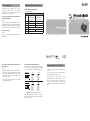
Figure A-1: Straight-Through and Crossover Cable
Please make sure your connected cables are with same pin
assignment and color as above picture before deploying the
cables into your network.
- 10 -
- 12 -
- 13 -
- 14 -