1
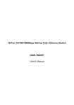
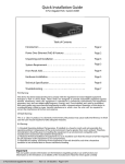
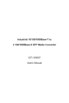
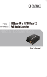
IEEE 802.3af
Power over Ethernet Injector
POE-151
User’s Manual
-1-
Trademarks
Copyright © PLANET Technology Corp. 2006.
Contents subject to revision without prior notice.
PLANET is a registered trademark of PLANET Technology Corp. All other trademarks belong to their respective
owners.
Disclaimer
PLANET Technology does not warrant that the hardware will work properly in all environments and applications,
and makes no warranty and representation, either implied or expressed, with respect to the quality, performance,
merchantability, or fitness for a particular purpose.
PLANET has made every effort to ensure that this User’s Manual is accurate; PLANET disclaims liability for any
inaccuracies or omissions that may have occurred.
Information in this User’s Manual is subject to change without notice and does not represent a commitment on the
part of PLANET. PLANET assumes no responsibility for any inaccuracies that may be contained in this User’s
Manual. PLANET makes no commitment to update or keep current the information in this User’s Manual, and
reserves the right to make improvements to this User’s Manual and/or to the products described in this User’s
Manual, at any time without notice.
If you find information in this manual that is incorrect, misleading, or incomplete, we would appreciate your
comments and suggestions.
FCC Warning
This equipment has been tested and found to comply with the limits for a Class A digital device, pursuant to Part
15 of the FCC Rules. These limits are designed to provide reasonable protection against harmful interference
when the equipment is operated in a commercial environment. This equipment generates, uses, and can radiate
radio frequency energy and, if not installed and used in accordance with the Instruction manual, may cause
harmful interference to radio communications. Operation of this equipment in a residential area is likely to cause
harmful interference in which case the user will be required to correct the interference at his own expense.
CE Mark Warning
This is a Class B product. In a domestic environment, this product may cause radio interference, in which case the
user may be required to take adequate measures.
WEEE Warning
To avoid the potential effects on the environment and human health as a result of the presence of
hazardous substances in electrical and electronic equipment, end users of electrical and electronic
equipment should understand the meaning of the crossed-out wheeled bin symbol. Do not dispose of
WEEE as unsorted municipal waste and have to collect such WEEE separately.
Revision
PLANET IEEE 802.3af Power over Ethernet Injector
FOR MODEL: POE-151
REVISION: 1.0(MARCH.2006)
Part No.: EM_POE151v1 (2080-A31120-000)
-2-
TABLE OF CONTENTS
1. INTRODUCTION.......................................................................................................................................... 4
1.1 CHECKLIST ................................................................................................................................................ 4
1.2 ABOUT THE POWER OVER ETHERNET INJECTOR........................................................................................... 4
1.3 FEATURES ................................................................................................................................................. 4
1.4 SPECIFICATION .......................................................................................................................................... 5
1.5 PRODUCT OUTLOOK ................................................................................................................................... 5
2. HARDWARE INSTALLATION .................................................................................................................... 6
2.1 PRIOR INSTALLATION .................................................................................................................................. 6
2.1.1 Before start up .................................................................................................................................. 6
2.1.2 POE-151, the Injector installation ..................................................................................................... 7
2.1.3 POE-151 and POE-151S, the IEEE 802.3af Injector and Splitter installation .................................. 7
2.1.4 Connect with IEEE 802.3af devices.................................................................................................. 8
3.TROUBLESHOOTING................................................................................................................................... 9
APPENDIX A NETWORKING CONNECTION............................................................................................... 10
A.1 SWITCH‘S RJ-45 PIN ASSIGNMENTS ......................................................................................................... 10
A.2 RJ-45 CABLE PIN ASSIGNMENT ................................................................................................................. 10
-3-
1. INTRODUCTION
1.1 Checklist
Thank you for purchasing our POE-151 IEEE 802.3af Power over Ethernet Injector, your Power over Ethernet
Injector package shall contains following contents:
Check the contents of your package for following parts:
z
Power over Ethernet Injector x1
z
User's manual CD x1
z
Power Adapter x1
z
Power cord x 1
If any of these pieces are missing or damaged, please contact your dealer immediately, if possible, retain the carton
including the original packing material, and use them against to repack the product in case there is a need to return it to
us for repair.
1.2 About the Power over Ethernet Injector
The POE-151 is an IEEE 802.3af Power over Ethernet Injector that provide DC 48V over Ethernet cables. The POE-151
IEEE 802.3af Power over Ethernet Injector inserts DC Voltage into Cat.5 cable, allowing the cable between the Injector
(POE-151) and Splitter (POE-151S-5V/9V/12V) to transfer data and power simultaneously. The maximum distance between the Injector (POE-151) and Splitter (POE-151S-5V/9V/12V ) is 100 meters. With POE-151 installed, it is combines
the Ethernet digital data with power over the twisted pair cables as an IEEE 802.3af Power over Ethernet Injector. And the
IEEE 802.3af Power over Ethernet splitter shall separate the digital data and the power into two outputs.
With IEEE 802.3af Power over Ethernet devices installed, the system administrator only have to use a single RJ-45
Ethernet cable to carries both power and data to each devices. Besides, to connect through POE-151 and
POE-151S-5V/9V/12V, you could also have following benefit that, cost saving, easy for networking planning and higher
reliability. What’s more, upon any IEEE 802.3af devices installed, the POE-151 or POE-151S-5V/9V/12V all can make the
connection while migrating or splitting the power and the Ethernet digital packets, such as connecting the POE-151 to an
IEEE 802.3af complied devices, AP or IP phone.
1.3 Features
◆
Comply with IEEE 802.3af Power over Ethernet, IEEE 802.3/802.3u 10/100Base-TX
◆
Provide DC 48V power over RJ-45 Ethernet cable to device with Ethernet port
◆
LED indicators power input indication
◆
Distance up to 100 meters
◆
Auto-detect of POE IEEE 802.3af equipment, protect devices from being damaged by incorrect installation
◆
Work with EIA568, category 5,4-pair cables for 10Base-T or 100Base-TX
◆
EMI standards comply with FCC, CE class B
-4-
1.4 Specification
Model
Ethernet Connector
POE-151
2 x RJ-45( 1 for data + DC in, 1 for Data out)
Ethernet Data rate
10/100Mbps( vary on Ethernet device attached)
Input voltage
DC 48V, 0.4A
Number of device can be powered
1
Ethernet cable
TIA/EIA-568, Category 5/5e cable
LED indicator
1 x power, 1 x POE ready / in-use
Dimension (W x D x H)
73 x 55 x 24 mm
EMI
FCC Class B, CE mark
Standard Compliance
IEEE 802.3 Ethernet,
IEEE 802.3u Fast Ethernet,
IEEE 802.3af Power over Ethernet.
1.5 Product Outlook
-5-
2. HARDWARE INSTALLATION
This product provides two different running speeds – 10Mbps, 100Mbps in the same device and automatically distinguishes the speed of incoming connection.
This section describes the hardware features of POE-151. Before connecting any network device to the POE-151, read this
chapter carefully.
2.1 Prior Installation
2.1.1 Before start up
Before your installation, please refer to the followings for your cabling:
100Base-TX
The 10/100Base-TX port comes with Auto-Negotiation capability. It automatically supports 100Base-TX and 10Base-T
networks. Users only need to plug a working network device into the 10/100Base-TX ports, then power on the POE-151.
The port will automatically runs in 10Mbps, 20Mbps, 100Mbps or 200Mbps after the negotiation with the connected device.
Cabling
The 10/100Base-TX ports use RJ-45 sockets -- similar to phone jacks -- for connection of unshielded twisted-pair cable
(UTP). The IEEE 802.3u Fast Ethernet standard requires Category 5 UTP for 100Mbps 100Base-TX. 10Base-T networks
can use Cat.3, 4, or 5 UTP (see table below). Maximum distance is 100meters (328 feet).
Port Type
Cable Type
Connector
10Base-T
Cat 3, 4, 5, 2-pair
RJ-45
100Base-TX
Cat.5 UTP, 2-pair
RJ-45
Any Ethernet devices can connect to the POE-151 by using straight-through wires. The 10/100Mbps port is
auto-MDI/MDI-X can be used on straight-through or crossover cable.
Before your installation, it is recommended checking your network environment. If there is any issue for your install a
networked device where is very difficult to find a power socket for your AC-DC adapter, POE-151 should provide you a way
to provide DC power for this Ethernet device conveniently and easily. The POE-151 comes with an AC-DC adapter with DC
48V input and injects this DC power into the un-used pin of the twisted pair cable (pair 4, 5 and pair 7, 8).
#Notice:
1. The POE-151IEEE 802.3af Power over Ethernet Injector will only work under Category 5 UTP/STP cable with 4-pair.
Please refer to appendix A for detail information.
2. Gigabit Ethernet device cannot be used to work with POE-151 since 1000Base-T will use the 4-pair for data transmission
(refer to appendix A). Co-work with POE-151, the speed will change to 100Mbps follow the port’s auto-negotiation.
3. The POE-151 and POE-151S can be installed in pair. However, the use of third-party device is allowed if the device
complied with IEEE 802.3af standard.
-6-
2.1.2 POE-151, the Injector installation
1. Connect a standard network cable from Switch/workstation to “Ethernet” port of POE-151.
2. Connect the long cable that will be used to connect to the remote device to the port “Ethernet + DC”. The screen in
Figure 1 appears.
3. Connect the AC adapter to “DC 48V” of POE-151. The power LED will be steady on.
Figure 1: the Injector installation
2.1.3 POE-151 and POE-151S, the IEEE 802.3af Injector and Splitter installation
1. Connect a standard network cable from “Ethernet+DC” of POE-151 to “Ethernet+DC” of POE-151S. The POE LED of
POE-151 / POE-151S will light on continuance. The screen in Figure 2 appears.
From POE-151 or
IEEE 802.3af Power
Supply equipment
Figure 2: Connection to POE-150S
2. Connect the UTP cable in the package from “Ethernet” of POE-151S to the RJ-45 port of remote device.
3. Connect proper DC plug from “DC OUT” of POE-151S to remote device.
4. Power on the remote device and the LED indicator on POE-151S will remains on, the screen in Figure 3 appears.
-7-
Figure 3: Connection architecture over POE-151/151S
#
Notice:
1. According to IEEE 802.3af standard, the POE-151 will not inject power to the cable if not connecting to
IEEE 802.3af devices.
2. Please ensure the output voltage is correct before applying power to remote device.
2.1.4 Connect with IEEE 802.3af devices
Due to the capability of IEEE 802.3af standard, the POE-151 can directly connect with any IEEE 802.3af end-nodes like
wireless access point, VoIP phones and Internet camera where support IEEE 802.3af In-line Power over Ethernet port. The
screen in Figure 4 appears.
Figure 4: Connection to IEEE 802.3af device
Once POE-151 detects the existence of an IEEE 802.3af device, the LED indicator will be steady, ON to shows it isproviding power.
#Notice:
If the connected device is not fully complying with IEEE 802.3af standard or in-line power device, the LED
indicator of POE-151 will not be steady on.
-8-
3.TROUBLESHOOTING
This chapter contains information to help you solve problems. If the Switch is not functioning properly, make sure the
Ethernet Switch was set up according to instructions in this manual.
The PoE LED is not lit
Solution:
Check the cable connection between POE-151 and IEEE 802.3af device.
Can the POE-151 work with Gigabit Ethernet device?
Solution:
The POE-151 use 4-wire for data transmission (pair 1, 2, pair 3, 6) and 4-wire for power supply (pair 4, 5, pair 7, 8), thus
Gigabit Ethernet device connect to POE-151 will not send data over the power wire and the transmit speed shall
change to 100Mbps.
Why I connect my PoE device to POE-151 and it cannot power on?
Solution:
1. Please check the cable type of the connection from POE-151 to the other end. The cable should
be an 8-wire UTP, Category 5 or above, EIA568 cable within 100 meters. A cable with only
4-wire, short loop or over 100 meters, all will affect the power supply.
2.
Please check and assure the device that fully complied with IEEE 802.3af standard.
-9-
APPENDIX A NETWORKING CONNECTION
A.1 Switch‘s RJ-45 Pin Assignments
RJ-45 Connector pin assignment
MDI
MDI-X
1
Media Dependant Interface
TX + (transmit)
Media Dependant Interface -Cross
Rx + (receive)
2
TX - (transmit)
Rx - (receive)
3
Rx + (receive)
TX + (transmit)
Contact
4, 5
DC current*
6
Rx - (receive)
7, 8
TX - (transmit)
Ground
Remark:
Gigabit Ethernet is not allowed to use POE-151 since pair 4,5 and pair 7, 8 are all being used for data transmission in
Gigabit Ethernet data transmission. Only 10Base-T and 100Base-TX can apply with POE-151 products.
A.2 RJ-45 cable pin assignment
6 32 1
6 321
….
3 21
The standard RJ-45 receptacle/connector
There are 8 wires on a standard UTP/STP cable and each wire is color-coded. The following shows the pin allocation and
color of straight cable and crossover cable connection:
Figure A-1: Straight-Through and Crossover Cable
Please make sure your connected cables are with same pin assignment and color as above picture before deploying the
cables into your network.
2080-A31120-000
- 10 -