1
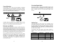
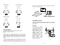
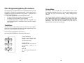
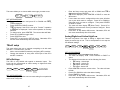
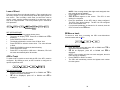
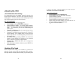
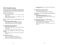
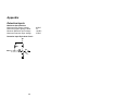
CR-2
Grade Crossing
Controller
Installation &
User Manual
Signalogic Systems
Signalogic Systems
3706 130A Avenue NW
Edmonton, AB T5A 5A4
Canada
February 2009
Ph: 780-719-3246
Fax: 780-475-6020
Email: [email protected]
1
2
Table of Contents
Signalogic Systems ...........................................................................2
Table of Contents ..............................................................................3
Introduction to the CR-2.....................................................................5
Two or More Track Crossings .......................................................5
Crossing Basics .................................................................................6
Multiple Tracks ..............................................................................8
CR-2 Layout and Connections.........................................................10
Connectors ..................................................................................10
Display.........................................................................................11
Joystick ........................................................................................13
Installing the CR-2 ...........................................................................14
Mounting......................................................................................14
Wiring ..........................................................................................14
Power ..........................................................................................14
Train Detection ............................................................................15
Optical Sensors.......................................................................15
Current-Detectors....................................................................17
Detection Input Modes ............................................................17
Crossing Signal Lights.................................................................18
Lighting Type...........................................................................18
Lighting Voltage ......................................................................19
Gate Motor Control ......................................................................20
Tortoise ...................................................................................20
Servo 1 / Servo 2 ....................................................................21
BL-2 Bell Module Connector .......................................................21
MT-2 Multi-Track Connector........................................................22
Task Menu...................................................................................23
Set-up Menu ................................................................................24
Gate Setup ..................................................................................26
Gate Setup ..................................................................................26
Gate Motor Type..........................................................................26
TRacK setup................................................................................27
INPut Settings .........................................................................27
Analog/Digital and Active High/Low ........................................28
Loss of Shunt ..........................................................................29
ADD a Track............................................................................29
REMove a track.......................................................................30
3
Bell Mode .................................................................................... 32
Gate Speed ................................................................................. 33
Gate Delay .................................................................................. 33
Servo Adjustments...................................................................... 34
Adjusting the CR-2 .......................................................................... 35
Train Detection Sensitivity .......................................................... 35
Shutting Off a Track .................................................................... 35
CR-2 Troubleshooting ..................................................................... 37
Appendix ......................................................................................... 39
Detection Inputs .......................................................................... 39
4
Introduction to the CR-2
Crossing Basics
The CR-2 crossing controller is an advanced device providing model
railroaders realistic operation of model grade crossing signals. The
CR-2 supports realistic:
•
Crossing signal lighting.
•
Gate operation
•
Bell sounds.
•
Operation with up to eight main line tracks via MT-2 modules.
The CR-2 is designed to operate railroad grade crossing signals as
close to prototypical standards as possible. To understand how the
CR-2 operates, the following section describes the basic operation
of a basic prototypical crossing.
The CR-2 allows the user maximum ease:
•
Minimal wiring
•
Menu driven setup (no cryptic settings)
•
Universal signal outputs provided.
Most commercially
available signals will work with the CR-2.
•
Accessory modules are pluggable.
Two or More Track Crossings
The CR-2 crossing system can accommodate up to eight tracks at
one crossing. To allow for more than one track, a MT-2 module is
required per track. The MT-2 provides the same detection interface
and train movement logic as the CR-2. This allows the MT-2 to
detect trains for the CR-2 to properly operate the crossing with these
additional tracks.
The fundamental circuit in any type of railroad signaling is the track
circuit. A prototypical track circuit is a length of track that is
electrically isolated for the purposes of detecting the presence of a
train within a defined area. Electrically insulated rail joint-bars are
used to accomplish this, just as we modelers do to isolate model
railroad tracks.
With these real track circuits, an electrical current is allowed to flow
from a battery through the rails from one end of the track circuit to
the other. Once the current reaches the opposite end of the track
circuit, the current passes from one rail to the other through a relay.
The current passing through the relay causes switch contacts to
close, allowing electrical control of additional functions.
Figure 1: Prototypical railroad track circuit
When a train occupies the track circuit, the steel axles creates a
short circuit, or shunt, across the track circuit. This causes the relay
to stop conducting current and the contacts open allowing detection
of a train.
5
6
Grade crossing signals are used to warn motorists of an
approaching train. To do so, a train must be detected automatically
before arriving at the road. A track circuit can be used to detect the
train and provide activation to the crossing signals.
Normally, trains can operate from either direction so the track circuit
must extend beyond the road in each direction to detect the train in
advance of its arrival. However, if only one track circuit is used then
the crossing will continue to operate until the last car of the train
vacates the far opposite end of the track circuit.
This is
unacceptable.
The solution is to provide separate track circuits for each side of the
road. These are called the approaches. With special logic, the
crossing can determine from which approach the train arrives on so
that after the train leaves the road the opposite approach can be
ignored. To ensure that the crossing always operates while a train
occupies the road, a third track circuit is used that encompasses the
road. This is called the island track or the crossing track (XT).
The CR-2 provides detection based on this prototypical
arrangement. The three track circuits of the CR-2 are identified as:
West Track Approach
Crossing/Island Track
East Track Approach
(WT)
(XT)
(ET)
The approaches can be any length. However, just as with real
railroads, the faster the trains are, the longer the approach must be
to provide enough warning.
Example:
A typical westbound train will occupy the crossing as follows:
•
•
•
•
•
•
Coming from the East, the train will first occupy the ET. At this
point, the crossing starts operating or ringing. The length of
the ET will define how much warning is provided for gates to
come down and lights to flash before the train arrives.
As the train reaches the road, the train will now be occupying
the XT as well.
Most trains will be long enough that the train will then also
occupy the WT before vacating the ET.
As the train continues, eventually the end of the train will clear
the ET.
A short time after, the train will clear the XT and at this point
the crossing stops ringing.
This happens because the
crossing establishes the direction of the train and ignores the
WT. The crossing has established that the train is moving
away from the road.
After the train leaves the WT, the crossing logic resets and is
ready to protect against another train from either direction.
The crossing will protect motorists properly even if:
•
A train is really short.
•
A train is really slow or stops on the approach.
•
Another train follows the first into the crossing.
Multiple Tracks
The CR-2 contains all the functions required to properly drive
railroad crossing signals and gates. In addition, it provides detection
and logic circuits for a single track. For multi-track crossings,
detection and logic circuits are required for each additional track.
These functions are provided with the MT-2: Multi-Track module.
MT-2 modules plug directly into the CR-2 system and provide data
about trains on additional tracks. The CR-2 listens to all installed
MT-2 modules as well as its own detection to control one set of
crossing signals that protect the road.
Up to seven MT-2 modules can be used to produce crossings with
up to eight main line tracks. Storage tracks that pass through a
7
8
crossing generally require only the XT detection implemented. This
allows cars to be placed near the road without operating the
crossing. Additional MT-2 modules are not needed to implement
storage tracks as discussed in the detection section.
CR-2 Layout and Connections
NOTE: The CR-2 and MT-2 modules do not operate like a ‘Grade
Crossing Predictor’ type circuit. These prototypical controllers allow
crossings to shut off if a train stops before reaching the road and
adjusts for when the crossing starts ringing to accommodate for
similar warning times independent of train speeds. The CR-2 and
MT-2 function as the simpler three-track type crossing described
above.
Connectors
1.
2.
3.
4.
5.
6.
7.
8.
9
Power
Detection
Lights
Tortoise
Servo A / Servo B
MT-2 Multi-Track Connector
BL-2 Bell Module Connector
Lighting Voltage Selector
10
time when the X is illuminated. As the train moves onto the XT, the
XT decimal point will illuminate and the display will change to:
Display
The CR-2 uses an alphanumeric device to display programming
menus and system status. Instructions will show typical screen
displays as follows: CR-2
During normal operation, when there are no trains present in the
crossing detection circuits, the display will be blank. However, when
trains are detected, the display will show if the crossing is ‘ringing’
and other information about train movements.
There are four decimal points on the display. The illumination of
each decimal point indicates different information. Three decimal
points denote the presence of trains in each of the three track
detection circuits (WT, XT and ET). The decimal on the left follows
the crossing signal flash rate. See the figure below.
1_X.W.
1_.X.E would be displayed for an eastbound train.
The E/W information is the direction of the train. After the train
moves off of the XT, the XT decimal point will extinguish and the
display will change to:
1_._W
Even though the train is still in the WT, the X disappears, meaning
the crossing stops ringing. If the crossing has gates, the gates will
ascend and the lights will flash until the gates are vertical. The CR-2
has established the direction of travel and ignores the WT because
the train is leaving.
Once the train leaves the WT, the CR-2 display will go blank
signifying that the system is back to an idle state and ready for the
next train.
Example: Westbound Train on Track 1
The train will first enter the East approach. The display will
illuminate the ET decimal point and the FLASH RATE decimal point
will flash at the crossing signal flash rate. The display will show:
•
__X_. if the crossing is a single track, or:
•
1_X_. if you have two or more tracks assigned.
The 1 denotes the track number that the train is on and can be the
numbers 1 through 8. The number one is always the CR-2
controlled track. Numbers 2 through 8 correspond to the seven
possible MT-2 modules in a crossing.
The X in the display means that the occupancy requires the crossing
to operate. If there are gates they will descend after the set delay
11
12
Joystick
Installing the CR-2
The CR-2 is equipped with a joystick control that is located in the
top-right corner of the module. The joystick is used to navigate the
CR-2 menu system for all programming and adjustments. The
joystick can be manipulated in five different directions as shown
below:
•
•
•
•
•
Up,
Down,
Left,
Right,
And Center.
Mounting
Using #4 wood screws, mount the CR-2 in a convenient location
where you can access the connectors with a screw-driver and insert
wires.
You will also need to access the joystick to make
adjustments to the system and setup the CR-2. MT-2 modules, if
used, will need to be plugged into the CR-2 and fastened.
Wiring
The CR-2 can be damaged if connections are not made correctly.
Wire the CR-2 without power. Once wiring is complete, the user
must ensure that the wiring is correct before applying power to the
system. Stranded wire increases the danger of short circuits due to
stray wire strands that may touch adjacent terminals or components
on the board. It is recommended that solid 18-24 AWG wire be
used.
Solid telephone wire or CAT-5 Ethernet wire is
recommended.
Providing a color code to your wiring is
recommended to allow ease of tracing in case of troubleshooting.
This manual shows the user how to accomplish all programming and
adjustments in a step by step manner. The joystick is required for
all of these tasks.
Where multiple wires must be placed in one terminal, ensure both
wires are secure before turning on the power. For plug-type
connections, make sure the connector pins are mated correctly and
not offset by one or more pins or damage to the system may occur.
Power
Power is delivered through a dedicated power connector located on
the left edge of the CR-2. The CR-2 can accept input power of 820VDC and is protected against incorrect polarity. A regulated DC
power supply is recommended instead of conventional power-packs.
13
14
NOTE: If you intend to use signals with 12V incandescent bulbs,
then the power source MUST NOT be greater than 12VDC or
adequate resistors must be used to ensure the bulbs do not burn out
pre-maturely.
Train Detection
Train detection is implemented by three track-circuits, WT, XT and
ET, as discussed in the Crossing Basics section above. These
inputs are accessed from the DETECTION connector on the lower
side of the CR-2. Three terminals are for detection inputs and the
fourth provides a common ground for the detectors to interface to.
Any type of detection that indicates the presence of a train can be
used if compatible with the detection inputs.
Optical Sensors
If storage tracks are present at your crossing, the XT is the only
detection required for those tracks. This allows cars to be stored
next to the road without operating the crossing. Additional MT-2
modules are not required. Simply include photocells for each
storage track into the XT photocell string of the CR-2. Any
occupancy of the storage track(s) will appear at the main track XT.
The default means to detect trains with the CR-2 is with the use of
standard optical photocells.
Optical sensors such as photocells or infrared receivers are placed
between the rails so that a passing train shadows the light that the
sensors are sensitive to.
These sensors provide acceptable
detection but require adequate light sources and only allow
detection of the train at discrete points. Providing more sensors
spaced closely together means that short trains will remain detected.
To install photocells, first locate where each photocell will be placed.
The XT is created with two photocells by placing a photocell on
either side of the road and connecting them in series. The
remainder of the photocells are placed within each approach with
the last one placed at a sufficient distance to provide enough
warning time.
Drill separate 1/16” holes between the ties for each lead of the
photocell. If the roadbed is too thick for the photocell leads, you
may need to solder wires to the photocells in order to make the
connections under your layout.
The photocells are connected in series as shown below. One end of
each string connects to the common terminal.
15
16
Crossing Signal Lights
Current-Detectors
Current-sensing devices offer the best detection by allowing
continuous detection of a train throughout a track-circuit. However,
current detection requires an interface to track feeders and rolling
stock must be equipped with an adequate number of detectable
axles to ensure the crossing sees the entire train.
If storage tracks are present at your crossing, create XT track
circuits for each storage track and include the circuits as the
mainline XT. Any occupancy will show as the mainline XT.
Detection Input Modes
The detection inputs operate in the range of 0-5VDC and can be
analog or digital. Analog inputs can be any value in the entire 5V
range while digital inputs can only be 0V or 5V. The user may also
set an input as active-high or active-low. An active high input would
mean that occupancy would be declared if the voltage is higher than
the threshold for an analog input and if the input is high for a digital
input. The opposite would be true for inputs set as active low.
The immediate value of any track input can be seen from the TRacK
SENSitivity menu: See section: Adjusting CR-2. Analog inputs will
be shown as a percentage from 0%-100% representing 0-5V
respectively. Digital inputs will be displayed as High or Low
corresponding to the digital level. See Appendix for additional CR-2
electrical specifications.
17
Signal bulbs or LEDs are connected to the LIGHTS connector on the
lower edge of the CR-2. Depending on the model of signal you are
using, four different output standards can be programmed into the
CR-2. In addition, either 5V or the input power voltage can be
selected.
Lighting Type
The CR-2 provides four output modes to be compatible with as
many signal manufacturers as possible. LEDs only illuminate with
the correct polarity and require the flasher outputs to match the
established polarities of the manufacturer. Incandescent bulbs are
not dependent to the output type of the CR-2 and should work with
all modes except: H-Bridge.
The following Table lists popular model signals available to
modelers and the required output settings of the CR-2 for that
model.
Manufacturer
N.J. International
Custom Signals
Details West
Model Power
Oregon Rail
Walthers
Signalogic Systems
Model Part #
All models
Output Type
CA
CS-913
CA
CA
All models
H-Brdg
18
Voltage
12V
12V
12V
12V
12V
12V
5V
Common Anode
Common Cathode
across two of the pins. Place the shunt across the pins as shown
below for the desired voltage.
Railroad Standard
H-Bridge
Gate Motor Control
The CR-2 is capable of driving crossing gates in a prototypical
fashion with either a single Circuitron Tortoise™ motor or two RC
servo motors.
Tortoise
Lighting Voltage
The CR-2 is capable of driving the signals at two voltages:
Input Power Voltage (8-20VDC)
5VDC
For LED signals, it is recommended that you use the 5VDC setting.
If the manufacturer recommends 12VDC, then the input power
voltage to the CR-2 MUST NOT be greater than 12VDC or
additional resistors must be placed between the CR-2 and the
signals.
The CR-2 can operate
crossing gates with the use of
a single Circuitron Tortoise™
slow-motion switch motor. A
linkage system is used to
connect one Tortoise™ to
multiple
gates.
The
Tortoise™ is connected to the
TORTOISE connector on the
lower edge of the CR-2. If the
Tortoise™ moves in the
wrong
direction
during
operation, simply swap the
wires to the terminals.
To select the lighting voltage, use the voltage selector connector
located just above the DETECTION and LIGHTS connector. The
connector has three pins with a jumper/shunt that is connected
19
20
Servo 1 / Servo 2
MT-2 Multi-Track Connector
The CR-2 can also drive
crossing gates with RC servo
motors.
Two servo motor
outputs are located on the
right edge of the CR-2. The
servo motor cable must have
a pin-out that matches the
CR-2 as shown to the right.
Crossings consisting of more than one track can be implemented
with the use of MT-2 modules. Each MT-2 controls one additional
track. If more than one MT-2 module is used, only one will plug into
the CR-2 XPND connector. Every other module will plug into the
next MT-2 creating a daisy-chained network. A cable is provided
with the MT-2 allowing it to plug into the CR-2 or neighboring MT-2.
Install each servo directly under the respective gate signal so that a
connecting rod can be aligned from the gate arm to the servo-motor
output shaft lever. Place the servo motor and gate arm in midposition before connecting the actuator linkage. This will ensure a
full range of motion for the gate movement.
BL-2 Bell Module Connector
Realistic
bell
sound
is
possible with the BL-2 sound
module which plugs directly
onto the CR-2. To install,
seat the BL-2 onto the BELL
receptacle plug allowing the
BL-2 to sit below the display.
The BL-2 has one speaker
output connector. Connect a
suitable speaker to the BL-2
and mount near the crossing
signals for best results.
Volume can be adjusted via
the volume control on the BL2.
21
22
CR-2 Programming/Setup Procedures
All programming and adjustments are accomplished with the use of
the joystick. All tasks are accessible through a menu system that is
navigated through the manipulation of the joystick. In general menu
navigation is standardized:
•
To select a menu item: press CENTER or RIGHT.
•
To cancel a task and move back one menu: press LEFT.
•
To change or accept a value, press CENTER.
•
To cycle through menus or values press UP or DOWN. You
may hold the joystick UP or DOWN to cause values to change
more quickly.
Set-up Menu
The set-up menu provides the user access to all of the
programmable settings of the CR-2. The user will probably find that
this menu will only be accessed when initially configuring the
crossing.
The following diagram depicts the relation of the menu items to each
other. Moving the joystick UP or DOWN will bring you to each item
accordingly. Some menu items are only available if gates are used.
Additionally, some items are only available if the gate drive is
selected to be of the RC servo-motor type.
Task Menu
The task menu is the entrance point to the CR-2 menu system.
From here, you can select menu items to make adjustments to the
system or to setup features for the first time.
Press the joystick CENTER to enter menus.
Use the joystick UP/DOWN to scroll through the menus.
TRacK SENSitivity:
View the current value of all
analog track circuits and
adjust the sensitivity.
TRacK STATus:
Allows the user to view and
set whether a track is in
service.
SET-UP:
All other setup accessed from
here.
23
24
GATE USED: Select if crossing is
equipped with gates.
GATE TYPE: Select either a
Tortoise™ or servo motor gate drive.
TRacK: Setup track detection inputs.
Gate Setup
The CR-2 can be used to operate crossings with or without gate
arms. Setting the CR-2 to operate with gates will activate circuitry to
control and monitor gate arm positions. Lights will remain flashing
until the gate arms return to the vertical position and the bell will
operate according to settings shown in subsequent sections.
FLaSH RATE: Flash rate for lights.
LITE MODE: Lighting output type for
signals.
BELL MODE: How bell operates
with gates.
UP SPEeD: Set the up speed of the
gate arms.
DOWN SPEeD: Set the down speed
of the gate arms.
GATE DeLaY: Set the time delay
before the gates start down.
SeRVo A UP Position: Set the up
position of gate A servo motor.
SeRVo A DowN Position: Set the
down position of gate A servo motor.
SeRVo B UP Position: Set the up
position of gate B servo motor.
SeRVo B DowN Position: Set the
down position of gate B servo motor.
25
SET-UP PROCEDURE
•
Enter the Setup menu and select the GATE USED item by
pressing CENTER or RIGHT.
•
If gates are currently being used, you will see YES displayed.
•
To change value, press CENTER. The current value will flash.
•
Press UP or DOWN to toggle value.
•
Press CENTER to save.
•
Press LEFT to step back to SET-UP menu. Otherwise, CR-2
will exit menu automatically after 30 seconds.
Gate Motor Type
The CR-2 allows two types of gate motion control:
•
Circuitron Tortoise™ motor
o One Tortoise™ operates both gate arms with the use of
mechanical linkages.
o The Tortoise™ motor drive uses Back-EMF technology
to ensure steady motion of the gate arms even when the
linkage system provides varying resistance as it travels.
•
Servo motors
o Two outputs are provided so that each gate has its own
servo.
This eliminates the complex linkage
requirements of the Tortoise™.
o Linkage adjustments are accomplished in software by
menu access in the CR-2. No mechanical adjustments
are necessary.
26
This menu allows you to choose which motor type you want to use.
•
•
SET-UP PROCEDURE
•
Enter the Setup menu and press UP or DOWN until GATE_
TYPE is displayed.
•
Press CENTER or RIGHT to select.
TORT will display if the CR-2 is set up for Tortoise™ operation
•
or SRVO will be displayed if servo motor operation is currently
selected.
•
To change value, press CENTER. The current value will flash.
•
Press UP or DOWN to toggle value.
•
Press CENTER to save.
•
Press LEFT to step back to SET-UP menu. Otherwise, CR-2
will exit menu automatically after 30 seconds.
•
•
•
Enter the Setup menu and press UP or DOWN until TRK is
displayed and press CENTER.
INP will be displayed, press CENTER or RIGHT to enter the
INPut menu.
If more than one track is configured then the menu will allow
you to pick which track to configure. Press UP or DOWN to
select the track you want to configure. Then press CENTER
or RIGHT to select.
The menu will then display WT (West Track). Press UP or
DOWN to select the track circuit you want to configure. Press
CENTER to select.
Press LEFT to step back to INPut menu. Otherwise, CR-2 will
exit menu automatically after 30 seconds.
Analog/Digital and Active High/Low
The user may select if the input is analog or digital and if these
inputs are active high or low. This is accomplished in one step as
four different settings.
TRacK setup
This menu allows the user to program everything to do with track
detection. From this menu, you can:
•
Add or remove additional tracks by configuring MT-2 modules.
•
Change the behavior of every track circuit input of the CR-2
and MT-2 modules.
INPut Settings
The CR-2 is very flexible with regards to detection inputs. The
inputs can be programmed as either analog or digital and either
active-high or active-low.
SET-UP PROCEDURE
The following steps describe how to access setting for one particular
track circuit or any track.
27
SET-UP PROCEDURE
•
Start with the Track Input steps shown above.
•
The menu will display TYPE. Press CENTER or RIGHT to
select.
•
The display will now show one of the following four items:
o AH: Analog - Active High
o AL: Analog - Active Low
o DH: Digital - Active High
o DL: Digital - Active Low
•
Press CENTER to edit the current value. The value will start
to flash.
•
Press UP or DOWN to select the desired setting.
•
Press CENTER to accept.
•
Press LEFT to step back to INPut menu. Otherwise, CR-2 will
exit menu automatically after 30 seconds.
28
Loss of Shunt
This term comes from real railroad signaling. Even actual trains can
have dirty wheels or rusty rails that may cause the signal system to
lose a train. This is usually a brief event, so timers are used to
ensure a track remains declared occupied for a short time after a
train is no longer detected. The CR-2 provides up to 5 seconds of
LOS protection.
•
•
•
•
SET-UP PROCEDURE
•
Start with the Track Input steps shown above.
•
The menu will display TYPE. Press UP or DOWN until LOS is
displayed.
•
Press CENTER or RIGHT to select.
•
The display will show the current ‘Loss of Shunt’ time.
•
Press CENTER to edit the current value. The value will start
to flash.
•
Press UP or DOWN to select the desired setting.
•
Press CENTER to accept.
•
Press LEFT to step back to LOS menu. Otherwise, CR-2 will
exit menu automatically after 30 seconds.
ADD a Track
To allow an MT-2 module to work with the CR-2, the MT-2 must be
configured. By ADDing a track, an MT-2 module is configured to
operate a particular track.
NOTE: If the crossing already has eight tracks assigned, then
this menu will not be available.
Press CENTER or RIGHT to select.
PRES BTTN will appear on the screen. The CR-2 is now
waiting for a response.
Press the pushbutton on the MT-2 that is being configured.
The CR-2 menu should change. The MT-2 is now configured
as the next available track.
If no pressed pushbutton is detected in 10 seconds, then the
CR-2 will revert to the ADD menu.
REMove a track
To remove a track from a crossing, the CR-2 must discontinue
communications with its MT-2.
SET-UP PROCEDURE
•
Enter the Setup menu and press UP or DOWN until TRK is
displayed and press CENTER.
INP will be displayed, press UP or DOWN until RMV is
•
displayed.
NOTE: If the crossing only has one track assigned, then this
menu will not be available.
•
Press CENTER or RIGHT to select.
•
The CR-2 will immediately remove the highest track number
from the system.
SET-UP PROCEDURE
•
Enter the Setup menu and press UP or DOWN until TRK is
displayed and press CENTER.
INP will be displayed, press UP or DOWN until ADD is
•
displayed.
29
30
Flash Rate
The CR-2 can provide a wide range of signal flash rates. Flash
rates are shown as Flashes per Minute.
SET-UP PROCEDURE
•
Enter the Setup menu and select the FLSH RATE item by
pressing CENTER or RIGHT.
•
The current flash rate will be displayed.
•
To change value, press CENTER. The current value will flash.
•
Press UP or DOWN to adjust value.
•
Press CENTER to save.
•
Press LEFT to step back to SET-UP menu. Otherwise, CR-2
will exit menu automatically after 30 seconds.
Bell Mode
This menu is only accessible if gates are used. With gate crossings,
differing railroad standards mean that a bell does not operate the
same way at all crossings. The CR-2 offers four different bell
modes:
SET-UP PROCEDURE
•
Enter the Setup menu and select the
pressing CENTER or RIGHT.
•
The current mode will be displayed.
MODE
_ON_
_XR_
G_DN
G_MV
31
BELL MODE item by
The bell rings:
If lights are flashing.
Until the gates start to move up.
Until the gates are horizontal.
When the gates are moving.
32
•
•
•
•
To change value, press CENTER. The current value will
flash.
Press UP or DOWN to adjust value.
Press CENTER to save.
Press LEFT to step back to SET-UP menu. Otherwise,
CR-2 will exit menu automatically after 30 seconds.
Gate Speed
The user has the ability to change the up and down gate arm
speeds. One menu allows adjustment of the up speed while another
controls the down speed. The adjustment procedures are identical.
Gate speed is depicted by a numerical value. A higher numeric
value translates to a faster gate speed.
SET-UP PROCEDURE
•
Enter the Setup menu and select the GATE DLY item by
pressing CENTER or RIGHT.
•
The current delay value (in seconds) will be displayed.
•
To change value, press CENTER. The current value will flash.
•
Press UP or DOWN to adjust value.
•
Press CENTER to save.
•
Press LEFT to step back to SET-UP menu. Otherwise, CR-2
will exit menu automatically after 30 seconds.
Servo Adjustments
Servo motors are designed so that control circuits can position the
motor shaft to a precise position. The CR-2 uses this advantage to
reduce the mechanical complexity that would be required with a
Tortoise™ motor. With servo motors, mechanical adjustments are
not required. Instead, the CR-2 is used to adjust the end points of
the servo motor travel once the simple linkage to the gate arm is
assembled.
SET-UP PROCEDURE
•
Enter the Setup menu and select the UP SPED or DOWN SPED item
by pressing CENTER or RIGHT.
•
The current speed rate will be displayed. The value ranges for
Tortoise™ motors and servo motors will be different.
•
To change value, press CENTER. The current value will flash.
•
Press UP or DOWN to adjust value.
•
Press CENTER to save.
•
Press LEFT to step back to SET-UP menu. Otherwise, CR-2
will exit menu automatically after 30 seconds.
Gate Delay
The user has the ability to change the gate descent delay. This is
the time from when the lights start flashing until the gates start to
descend.
33
The following instructions apply to the vertical and horizontal
positions for both servo motors. Ensure the linkage rods to the
servos are finalized before beginning this process:
SET-UP PROCEDURE
•
From SeRVO Position menu, press CENTER or RIGHT.
Current position value will be displayed.
•
Press CENTER to edit value. Servo motors will travel to the
programmed position and displayed value will flash.
•
Press UP or DOWN to adjust. Servo motor will change
position accordingly.
•
When proper vertical or horizontal position is attained, press
CENTER to save new position.
Gates may move
unexpectedly for a brief moment.
34
Adjusting the CR-2
Train Detection Sensitivity
For analog inputs such as standard photocell detection, the
CR-2 must be calibrated. The CR-2 uses a percent scale for
analog inputs. You can view the current analog input value
and set the threshold value for valid occupancy.
SET-UP PROCEDURE
•
Press CENTER to enter selection menu.
•
Press DOWN or UP until TRK SENS is displayed.
•
Press CENTER or RIGHT. For a single track crossing,
there is no track to select and you are brought directly to
step 5. For multi-track, you will see 1TRK denoting the
track number.
•
Press UP or DOWN to scroll to the required track circuit,
and then press CENTER.
•
Pressing UP or DOWN will scroll through WT, XT and ET
current settings. If it’s a digital input, you will see if the
input is High or Low. If it is analog, then you will see the
percentage value.
•
For analog values, pressing CENTER will cause the
display to start flashing and change to the threshold
value. There are no effects for digital inputs.
•
Pressing UP or DOWN will allow you to change the
threshold value.
•
After selecting the desired threshold, press CENTER to
accept the change.
a train on one track. The CR-2 allows you to take an entire
main track out of service for this reason.
SET-UP PROCEDURE
•
Press CENTER to enter selection menu.
•
Press DOWN or UP until TRK STAT is displayed.
•
Press CENTER or RIGHT.
•
Press UP or DOWN to scroll to the required track.
•
Press CENTER to toggle the track on or off.
•
When viewing the status display, any tracks that are out
of service will have a letter ‘D’ displayed:
1__D: The D denotes Disabled.
•
Shutting Off a Track
There may be times when it is desirable to override the
detection circuitry on the CR-2 or associated MT-2 modules.
Perhaps detection circuitry becomes faulty or you want to park
35
36
CR-2 Troubleshooting
•
Ensure servo settings for horizontal and vertical positions
are properly set.
If your crossing system is not behaving as you expect then it is
likely that some user wiring is incomplete or some settings are
not programmed correctly. The following pages list typical
problems and potential solutions.
Crossing signals do not flash correctly.
•
Ensure wiring to signals is correct.
•
Ensure correct lighting output type is programmed.
CR-2 does not respond at all.
•
Check that power source is on and within required
voltage range.
•
Check that power source wire polarities are not
backwards on power terminal.
Crossing does not stop operating until train departs last
track-circuit.
•
Ensure detection wiring is correct.
•
Ensure adequate sensitivity is set for detection.
•
Increase Loss-of-Shunt time for track circuits and see if
problem disappears.
CR-2 is functional but the crossing signals do not
function.
•
Ensure wiring to signals is complete.
•
Ensure output type is set correctly for your signals.
•
Ensure detection is wired correctly to start crossing.
•
Ensure sensitivity is set correctly for analog inputs.
Crossing signals operate in an intermittent fashion.
•
Ensure wiring is correct.
•
Ensure detection sensing is adequate for train detection.
•
Ensure Loss-of-Shunt time is adequate.
•
Ensure that the track is clean when using current
detection.
Crossing signals do not stop operating.
•
Ensure detection wiring is intact.
•
Ensure detection input type is set correctly for detection
system used.
•
Ensure any MT-2 modules are connected to CR-2.
Crossing stops operating only when train occupies
crossing.
•
Change detection inputs from active high to active low or
vice versa.
Gate motors do not move.
•
Ensure CR-2 is programmed to use gates.
•
Ensure the correct type of gate motor is selected.
•
Ensure motor connections are complete to the CR-2.
37
38
Appendix
Detection Inputs
Maximum Specifications
Maximum Input Power Voltage:
Maximum Signal Lighting Current:
Minimum Detection Input Voltage
Maximum Detection Input Voltage
Detection Input Equivalent Circuit
39
20VDC
1A
-10VDC
15VDC