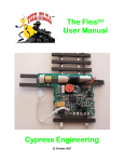
1
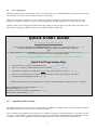
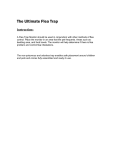
The Flea III User Manual Cypress Engineering 3 September 2009 1.0 Introduction Congratulations on your purchase of a Flea III switch machine actuator with integral DCC accessory decoder. This is a precision assembly that is factory installed on Walthers code 83 switches. The Flea III incorporates a miniature motor and gearbox that provides smooth, authentic motion during switch transitions. The FLEA III™ can be installed and operated, with DCC, without drilling any holes or running any wiring. Optional features such as remote LED indication and Automatic Switch Operation require under the table wiring. No under the table mounting of any components is required. The integrated FLEA III / Code 83 Turnout is a precision mechanism. It should be handled accordingly. Avoid bending or flexing the turnout in any manner. It can cause open circuits in the DCC jumper straps and binding in the points. Larger models such as the double crossover, double slip and large radius curved switches should be held in the middle, never from one end The Flea III is for operation in DCC layouts. The switch position can be controlled from a combination of the DCC controller and/or a pushbutton. This manual is written for Version 3.0 of the Flea III software, see the Appendix for a list of changes since version 2.0. The software comes with two options: Option A is for right hand turnouts, it has a default address of 129 and is identified by a red stick on Dot.. Option B is for left hand turnouts, it has a default address of 128 and is identified by a blue stick on Dot. The motor turns in opposite directions in the two options. There are no other differences between options A and B. The Flea III has an on board LED whose purpose is to provide information about the Flea III immediately following power up. On power up the LED blinks out the address of the decoder, the software version and the software option (A/B). It also provides verification when a CV has been programmed. The Flea III is capable of being programmed for route operations and can inter-operate with the Hare’s Smart Routes. 1.1 Addressing The decoder in the Flea III has its own address. This makes it possible for a DCC command station to send messages uniquely to it. The default address should be changed prior to installation in the layout. Otherwise more than one Flea III may respond to each command. After the address has been programmed the Flea III will permanently remember it until such time as it is changed again. NOTE: The decoder address in the Flea III serves two purposes: Not only is it the accessory decoder address where switch Throw and Clear commands are sent but also it is the loco address where programming commands are sent. When choosing an address for the Flea III it is important that it be available both as an accessory decoder address and as a four digit loco address to avoid duplication of addresses. The Flea III does not respond to two digit loco addresses. The default addresses are 128 and 129 for the Option B (Blue dot) and Option A (Red dot) software respectively. In situations where a turnout requires two Fleas II, that can only be powered simultaneously, (such as double slip switches and three way switches) one will have Option A software and the other will have Option B. This allows them to be individually addressed, and programmed to their own unique address. They can then be programmed independently. The Flea III may be programmed to any address in the range 128 to 2000 but check your command station and throttle to determine if the whole range is accommodated. It is important to keep a record of the decoder address for future use but if the address does become lost it may be read from the LED as part of the power up message. CAUTION: Programming two switches to the same address MUST be avoided. Keep a list of your switches with their addresses. A good idea would be to select a block of addresses for switches, large enough to cover all future needs, and use the next number in succession whenever a new switch is added to the layout. The LED blinks out the address of the switch on power up. This is a very helpful feature to avoid addressing conflicts. 2 1.2 Power Up Message Immediately following power up, the Flea sends a power up message to the on board LED. This provides information about the decoder address, the software version number and software option letter. First the decoder address is displayed as a series of pulses representing each digit. For example the default address of 128 is displayed as one pulse followed by two pulses followed by eight pulses. A single long pulse is used to represent a zero digit. Next the software version is displayed in similar fashion. For example version 3.0 is displayed as three pulses followed by a long pulse. Finally, a single pulse signifies Option A and a double pulse indicates Option B. QUICK START GUIDE First verify proper functioning of the turnout If you will only be operating with a Pushbutton Switch all you have to do is hook up the switch (Section 3.0). Operate the Pushbutton switch with DC or DCC power temporarily applied to the outside rails. OR For DCC operation: Issue CLEAR/THROW commands with DCC power temporarily applied to the outside rails. (Section 1.1) Hint – see the Appendix for keystroke examples using Digitrax NCE and MRE. Next: If you will be operating with DCC the Flea must be programmed before installation (Section 6.0) Quick Start Programming Steps 1. Write down the current address of the Flea III™ here __________ (Section 1.2) 2. Choose a new address for the Flea III™ and write it down here __________ (Section 1.1) 3. Program the new address into the Flea at the current address using CV16, CV17, CV18 (Section 6.1) 4. From now on you must use the new address, the Flea III™ will no longer respond to the previous address. 5. If required, hook up a pushbutton switch (Section 3.0) The turnout should now respond to pushbutton presses and/or to DCC Clear/Throw commands sent to the new address. Did the LED pulse after each CV was programmed? (Section 6.0) Did you use Ops Mode? (Section 6.0) Did you enter the current address as a 4 digit address? (Section 6.0) Did you choose a valid new address? (Section 1.1) 2.0 Operation by DCC Control The Flea III will respond to Accessory Decoder “CLEAR” and “THROW” commands issued to its decoder address. Authentic, prototypical operation is assured by the motor and gearbox actuator. It is recommended to program the decoder address prior to installation in the layout, the default addresses of 128 and 129 should not be used, as a final address, or unexpected results may arise due to inadvertent programming when the default address is used on a future occasion. See the Appendix for specific operating instructions for some of the popular command stations. 3 3.0 Pushbutton Control When the pushbutton is pressed the turnout will change to the alternate position and remain there until another command is received either from DCC or by another actuation of the pushbutton. A simple single pole, single throw (SPST) pushbutton is all that is required. It should have “normally open” contacts. The pushbutton is connected as shown in FIGURE 1. 4.0 Electrical Connections FIGURE 1 shows the connections for the Pushbutton, remote LED, and the Automatic Switch Control option. Two pin Male connectors are provided for making connections to the on board Female terminal block. The Male connectors are designed for easy soldering of wires in the solder cups. DO NOT ATTEMPT TO SOLDER ANY WIRES DIRECTLY TO THE CIRCUIT BOARD! Two 2 Pin Male connectors are provided with the standard board. These are for the Push Button connection and the Remote LED connection. The board with the Automatic Switch Control has two additional 2 Pin Male connectors to accommodate the connections to the track sensors in the “CLEAR” and “THROW” legs. DO NOT LOSE THESE CONNECTORS! They are costly to replace. NOTE: When locating the isolated or “spot” rail sections to control the Automatic Switch action, take into account that the switch takes about one second for a transition. You must have enough distance between the “spot” rail and the switch frog that the fastest train will take at least one second (actually a little more for a safety factor) to travel this distance. NOTE: Do not make any connections to terminal contacts 7, 8, 9 or 10. These are used for factory programming only. External connections to these contacts could damage the circuit board. These contacts have been taped over to prevent connections. FIGURE 1. 4 5.0 Routes As well as the main decoder address it is possible to program up to 28 additional addresses that the Flea III will respond to for the purpose of routing. Unlike the decoder address that serves both as an accessory decoder address and as a loco address, the route addresses function only as accessory decoder addresses. Route addresses may range from 128 to 2000 but check your command station and throttle to determine if the whole range is accommodated. The default addresses of 128 and 129 should be avoided. By programming the same route address into a number of Flea IIIs a single Clear or Throw command issued to the route address will cause each of the Flea IIIs in the route to carry out the command. Each Flea IIIs’ response to the command is determined by its action value for that particular route. 5.1 Route Action Values To facilitate desired route setting, each route in each Flea III may have its own action value, this determines what action to take in response to Clear and Throw commands sent to a route address. Action values have four possible settings as described in the following table. VALUE 0 1 2 3 5.2 RESPONSE TO A CLEAR COMMAND CLEAR THROWN THROWN CLEAR RESPONSE TO A THROW COMMAND THROWN CLEAR THROWN CLEAR Route Time Delay An additional feature of the Flea III, when being controlled as part of a route, is that each Flea III introduces a random time delay following a command before that command is carried out. This is to help avoid having all Flea III motors drawing current at the same time and placing a heavier burden on the power supply. The random time delay is between 0 and 10 seconds. 6.0 Programming Programming the Flea III involves setting the values of Configuration Variables (usually referred to as CVs). It is important to note that all programming of the Flea III is done to the four digit loco address in “Ops” mode. See the Appendix for specific operating instructions for some of the popular command stations. Each time a configuration variable accepts a programmed value the on board LED is pulsed to indicate success of the programming operation. 6.1 CV16 CV17 CV18 These three configuration variables are used to program the decoders’ address. The three CVs must be programmed in order as follows: a) Set CV16 to 0 b) Set CV17 to the upper two digits of the four digit decoder address c) Set CV18 to the lower two digits of the four digit decoder address For example, to program the address 0257 set CV16 = 0, CV17 = 02 (or just 2 will do), CV18 = 57. Any time a mistake is made simply start over with CV16. After the address has been changed, all subsequent programming must be directed to the new address. 5 6.2 CV51 This configuration variable allows the power up position of the switch to be modified. The default value of 0 results in no action and the switch remains in its current position. Programming a value of 1 will cause the switch to assume the Clear position at power up. Programming a value of 2 will cause the switch to assume the Thrown position at power up. 6.3 CV63 Programming a value of 42 will return the Flea III to factory defaults and any prior programming will be lost. The LED is pulsed four times to indicate the Flea III has been successfully returned to factory defaults.. 7.0 Route Programming The Flea III may be programmed with up to 28 route addresses and corresponding action values. The routes are numbered 1 through 28. Action values have a range of 0 – 3 and a default of zero. Any action value may be left unprogrammed if desired. 7.1 CV16 CV17 CV18 (Route Address Without Action Value) These three configuration variables are used to program a route address while leaving the action value unchanged. The three CVs must be programmed in order as follows: a) Set CV16 to the route number (1 – 28) b) Set CV17 to the upper two digits of the four digit route address c) Set CV18 to the lower two digits of the four digit route address For example, to program the address 0468 into route 9 set CV16 = 9, CV17 = 04 (or just 4 will do), CV18 = 68. Any time a mistake is made simply start over with CV16. 7.2 CV16 CV17 CV18 CV19 (Route Address With Action Value) These four configuration variables are used to program route addresses together with associated action values. The four CVs must be programmed in order as follows: a) Set CV16 to the route number (1 – 28) b) Set CV17 to the upper two digits of the four digit route address c) Set CV18 to the lower two digits of the four digit route address d) Set CV19 to the action value (0 – 3) For example to program the address 1234 into route 6 with an action value of 2 set CV16 = 6, CV17 = 12, CV18 = 34, CV19 = 2 Any time a mistake is made simply start over with CV16. 6 APPENDIX 1 – Digitrax DT400 Throttle Operation 1 Programming Configuration Variables (CVs) Press [EXIT][LOCO] Display shows something similar to this. Stat‘ 128’ SEL Lo0128 Use keypad to enter the address of the Flea to be controlled: [3][4][5] Stat‘ 128’ SEL Lo0345 Press [PROG] repeatedly until Po shows On the bottom line Ad2 = ??? CVNo Po0345 Using the left hand throttle set the number of the CV to be programmed: [51] 051 = ??? CVNo Po0345 Using the right hand throttle set the value for the CV to be programmed: [1] 051 = 1 CVNo Po0345 Press [ENTER] and observe the LEDs blink as the command is accepted 2 063 = 1 CVNo Po0345 Sending Clear and Throw Commands to the Flea SW SEL 128=t SwSEL Use keypad to enter the address of the Flea to be controlled: [3][4][5] SW SEL 345=t SwSEL Press [c] or [t] as desired: [c] The command is sent to the Flea SW SEL 345=c SwSEL Press [EXIT] [SWCH] Display shows something similar to this. 7 APPENDIX 2 – NCE Procab operation 1. Programming Configuration Variables (CVs) Press [PROG/ESC] Display shows something similar to this. SEL MODE 12:47PM PROGRAM ON THE MAIN Press [ENTER] Display shows something similar to this. OPS PROG 12:57PM PROG LOCO:_128 Use keypad to enter the address of the Flea to be controlled: [3][4][5] OPS PROG 12:57PM PROG LOCO:_345 Press [ENTER] Display shows something similar to this. OPS PROG 12:57PM 1=ADR 2=CV 3=CFG Press [2] Display shows something similar to this. PROG CV 12:57PM ENTER CV NUM: Use the keypad to set the number of the CV to be programmed: [5][1] PROG CV 12:57PM ENTER CV NUM:51 Press [ENTER] Display shows something similar to this. PROG CV 12:57PM ENTER VALUE: Use the keypad to set the value for the CV to be programmed: [1] PROG CV 12:57PM ENTER VALUE:1 Press [ENTER] and observe the LEDs Blink as the command is accepted PROG CV 12:57PM ENTER CV NUM: Press [PROG/ESC] to exit. 2. Sending Clear and Throw Commands to the Flea Press [SELECT ACCY] Display shows something similar to this. CONTROL 11:50 ACC NUMBER: 128 Use keypad to enter address of the Flea to be controlled: [3][4][5] Press [ENTER] ACC: 345 11:50 1=N(ON)2=R(OFF) Press [1] or [2] as desired: [1] (1= Clear and 2=Throw) The command is sent to the Flea ACC: 345 11:50 1=N(ON)2=R(OFF) 8 APPENDIX 3 – MRC Operation 1. Programming Configuration Variables (CVs) Press [PROG] twice. Display shows something similar to this. Prog Main Track Press [ENTER] Display shows something similar to this. Loco 0128 Main Track Use keypad to enter the address of the Flea to be controlled: [3][4][5] Loco _345 Main Track Repeatedly press [ENTER] until CV# shows on the upper line. CV# _ _ _ Main Track Using the keypad set the number of the CV to be programmed: [5][1] CV# _ 51 Main Track Press [ENTER] Display shows something similar to this. CV _ _ _ Data Main Track Using the keypad set the value for the CV to be programmed: [1] CV _ 1 Main Data Track Press [ENTER] and observe the LEDs blink as the command is accepted. CV _ 1 Main Data Track 2. Sending Clear and Throw Commands to the Flea Press [ACCY] Accy ___ Use the keypad to enter the address of the Flea to be controlled: [2] [4] [5] Address can only be between 128 and 255. Accy Press [ENTER] Display shows something similar to this. Accy 1or2 245 Press [1] or [2] as desired: [2] 1=Clear and 2=Throw The command is sent to the Flea Accy OFF 245 245 9 Appendix 4 – Software Revisions REVISION 2.0 2.1 2.2 2.3 2.4 3.0 CHANGES Initial release of this version Power up message added (see section 2.1) Dual mode added (see section 4.0) CV51 added (see section 6.3) Timing extended to accommodate Digitrax DCS100 Toggle switch removed. Single LED on board 10