1
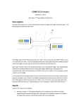
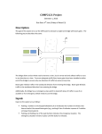
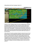
Exhibit A
PORTABLE TRAFFIC MANAGEMENT SYSTEM
1.0 General
1.1 Description. For six months, provide and maintain portable solar powered traffic
management system along a portion of Interstate 44 in Eureka, Missouri. Operate a
web site that enables MoDOT staff with access to the Internet to monitor and control the
system.
Provide the equipment on approximately four miles of I-44 including the Interchange 264
(Rt. 109) and Interchange 261 (Six Flags Rd.) The equipment shall consist of traffic
sensors, dynamic message signs, surveillance cameras, and communication equipment
linking the sensors, signs, and cameras to a web site. Exhibit 1 shows the approximate
locations of the sensors, signs, and cameras. The equipment may be trailer-mounted or
mounted on wood posts and poles.
The system provider must demonstrate 2-3 years of similar experience providing
portable traffic management systems that include video surveillance.
The system must be operational by May 1, 2006 and shall remain operational through
October 31, 2006.
2.0 Materials
2.1 Traffic sensors shall be radar-type units that report volume, occupancy, and speed
by lane. Provide evidence of the proposed unit’s accuracy and references that can
attest to its durability.
2.2 The dynamic message signs shall be line matrix or full matrix signs with pixels
formed by amber light emitting diodes (LEDs). The LEDs shall have a 30-degree
viewing cone. The sign shall have three lines of 18” characters. Lines shall be at least
48 pixels (8 characters) wide. The sign’s light output shall meet the requirements of
NEMA TS-4 for battery-powered signs and shall be dimmed at night. The bottom of the
sign shall be at least seven feet above the traveled way.
2.3 Cameras shall have the ability to pan, tilt, and zoom. They shall automatically
adjust the focus and iris, but those adjustments shall be overridden by commands from
the user. They shall be able to move to any of at least ten preset views and shall display
the view title on the picture. When the camera is not displaying a preset view, it shall
display the title (if any) assigned to the sector at which it is looking. The resolution shall
be at least 460 horizontal TV lines and the optical zoom shall be capable of providing a
magnification range of at least 1 to 22X.
2.5 Traffic control devices, including guard rail or any other structure placed within
highway right of way, shall meet the requirements of the Missouri Standard
Specifications for Highway Construction and MoDOT’s Quality Standards for Temporary
Traffic Control Devices.
1
EXHIBIT 1
PRELIMINARY EQUIPMENT LAYOUT
S
S
C
DMS
S
C
C
S
DMS
S
DMS
TRAFFIC SENSOR
TRAFFIC CAMERA
DYNAMIC MESSAGE SIGN
2
S
S
DMS
C
DMS
S
3.0 Construction Requirements
3.1 Detailed Design. Prepare a detailed design for the traffic management system and
purchase no equipment until the design is approved. The system must perform as
follows:
•
Unobstructed camera coverage of traffic exiting westbound I-44 at Exits 261 and
264 and traffic exiting eastbound I-44 at Exits 261 and 264. The camera must be
able to view at least 80 percent of each ramp plus the mainline traffic
approaching each ramp. Video shall be color, 15 picture refreshes per second.
•
Volume occupancy and speed data for each I-44 lane at half-mile intervals. The
westernmost traffic sensor location shall be approximately half a mile before the
start of the ramp from eastbound I-44 at Exit 261. The easternmost sensor
location shall be approximately half a mile before the start of the ramp from
westbound I-44 at Exit 264.
•
On each exit ramp or “exit only” lane, detection of stopped traffic about 100 feet
from the point where the ramp or lane diverges from the main line.
•
Dynamic message signs in advance of each exit point. The signs must be no
closer than a quarter mile and no farther than a half mile in advance of the exit
point. They shall be visible from all mainline lanes for a distance of 1,000 feet in
advance of the sign.
•
Continuously available communication between each device and the web site.
The communication system shall allow at least two cameras to be viewed
simultaneously, and provide resolution equivalent to 640 x 480 pixels, with at
least 15 picture refreshes per second.
The design shall include:
•
Exact locations for all roadside equipment. The number of devices and their
locations may be different from those shown in Exhibit 1. For each device,
include the mounting height above the roadway and the mounting configuration,
trailer or ground mount.
•
Catalog cut sheets for all devices, including cabinets, support structures, traffic
protection devices, power supply, and communication equipment.
This
information shall demonstrate that the devices meet all the requirements of this
special provision. Include a cut sheet for the proposed rain repellent for the
cameras.
•
Structural analysis of each support structure, including trailers, signed by a
professional engineer registered in Missouri.
•
Approved traffic control plan in accordance with MoDOT’s Traffic Control for Field
Operations (located at http://www.modot.org/business/manuals/trafficcontrol.htm)
3
shall be in place during the deployment and removal of the portable
transportation management system. Proposed traffic control plan shall be
submitted to and approved by the Engineer prior to deployment of the system.
•
A block diagram and explanatory write up of the proposed communication
system.
•
A draft user’s manual for the web site, showing every screen the user will
encounter. The manual should demonstrate that the web site shall meet the
requirements in this special provision.
•
The graphic (base map and device symbols) proposed for the web site’s map of
the area.
•
Photos or video clips taken from the proposed camera locations, at the height
that the camera will be mounted, demonstrating that the video coverage meets
the requirements stated above. MoDOT will provide a bucket truck for the
camera surveys.
•
Calculations demonstrating that the proposed solar power systems will have the
capability to:
o
o
Keep the equipment operating normally during two weeks without sun.
Recharge the discharge batteries while also powering the equipment with
16 hours of full sun.
Revise the design as directed by the Engineer to meet the specifications and resubmit it
as many times as necessary until approved by the Engineer.
3.2 Construct the system in accordance with the approved design.
3.3 Provide and operate an internal only web site that permits the MoDOT staff to use
the detectors, signs, and cameras. This web site shall have the following features.
•
Users will need no special software on their computers. Assume the users’
computers have a Windows 2000 operating system, an Internet browser, a
DVD player, Microsoft Media Player, ActiveX, and Apple QuickTime.
•
Each user shall have an individual password and a set of privileges set by the
system administrator. People without an authorized password shall not have
access to the site. The privilege system shall include at least three
categories of user: system administrator (able to perform all functions,
including assigning passwords and privileges to other users); operators (able
to aim the cameras and post messages), and viewers (able to see the
information coming from all devices, but unable to control the devices).
•
At least 10 users shall be able to access the site simultaneously, viewing
video without degrading performance. One operator should be allowed to
control the system at any particular time.
4
•
The main screen shall be a map or diagram of I-44 in the project area. It
need not be to scale, but must show the individual lanes on I-44 and the
ramps. It shall show each detection zone in each lane, each camera, and
each dynamic message sign.
•
Detection zones shall be represented by colored arrows oriented with the flow
of traffic. When the average speed in the lane is above 45 MPH, the arrow
shall be green. When below 25 MPH, red. Otherwise, yellow. If no current
data is available, the arrow shall be gray. When the cursor hovers over one
of the arrow symbols, a box shall appear giving the volume (vehicles per
hour), occupancy (percent), and speed (miles per hour) in that lane. The
values shall be averages (or smoothed averages) of values measured at one
minute (or less) intervals. The arrow color and related data shall be updated
automatically every minute with no need for any action by the user.
•
Dynamic message signs shall be represented by colored icons, green for
blank signs, yellow for signs with messages, and gray for signs that are
malfunctioning or cannot be monitored. When the cursor hovers over a sign
symbol, a box shall appear giving the text of the message currently being
displayed. If the message on the sign is unknown (because of a sign or
communication malfunction), the box shall say so. When an authorized user
left-clicks on a sign symbol or hyperlink, a window shall pop up, allowing the
user to change the message on the sign. The rectangle color and current
message shall be updated whenever conditions change, with no need for any
action by the user.
•
Cameras shall be represented by camera-shaped icons. They shall be blue
for working cameras and gray for cameras that are malfunctioning or cannot
be monitored. When the user left-clicks on a camera symbol, a window shall
pop up displaying the video from the camera. If the user is authorized to
control the camera, the window shall include a control panel that permits
camera aiming, zooming, and manual override of the automatic iris and focus
functions. This window shall enable the user to call up a preset view by
selecting the view from a list of views. It shall be possible to display the video
from the camera full screen. If an authorized user right clicks on the camera
icon, a window will pop up that allows the user to create and name preset
views and named sectors. The icons shall automatically change color to
reflect the operational status of the cameras with no need for any action by
the user.
•
The system shall provide travel times through the designated project area
and be able to display this information on the DMS devices automatically.
The system shall also detect and report the beginning and end of alarm
conditions, including:
o
o
o
o
o
Slow traffic (less than 25 mph) near the beginning of an exit ramp
Slow traffic (less then 25 mph) on the mainline
Stopped traffic near the beginning of an exit ramp
Stopped traffic on the mainline
No communication to multiple devices
5
o
o
o
o
o
Intermittent communication to multiple devices
No communication to (or no response from) one device
Intermittent communication with one device.
Loss of video from a camera
Low battery
A communication failure shall exist when a device does not respond to a
command sent by the user or a computer at the web site, unless it responds
to an automatic retry. The failure shall be labeled “no communication” until a
later command produces a response. At that point, the log shall show the
end of the “no communication” alarm and the beginning of the “intermittent
communication” alarm. The system shall not be considered recovered until it
has operated for one hour without another communication failure.
•
The map shall have an icon for alarms. When a user left-clicks on this
symbol, a window shall pop up displaying the alarm log. The log shall display
the occurrence alarm conditions in chronological order, most recent first,
except that all current alarm conditions shall be at the beginning of log (in
chronological order) regardless of when they first occurred. The current
alarms shall be listed in a bold font, while alarms that are no longer current
shall be in a regular font. As alarm conditions change, the log display shall
automatically change accordingly. For each event, the log shall list the
following information:
o
o
o
o
o
•
Device(s) affected
Device location
Description of condition
Start date and time
End date and time
The system shall automatically notify certain people of alarm conditions via email. For each type of alarm, the system administrator shall provide a list of
e-mail addresses to which the notification should be sent. The system
administrator shall be able to update these addresses at any time.
3.4 Provide and operate an external web site that permits public access to real-time
traffic information that is refreshed every 60 seconds with current camera
snapshots, current DMS messages and current average speed that is displayed in
pop-up message box when the mouse curser is positioned over an icon depicting
the approximate location of the field devices on map display. The information
contained within the message box shall be time and date stamped to indicate the
time of the last refresh of traffic information.
3.5 Device Setup
3.5.1 Configure each sensing device so that there is a detection zone covering each
lane at the location. Calibrate and test the sensors to provide accurate measurements
of volume, occupancy, and speed. Calibration shall be done or overseen in the field by
someone certified by the sensor manufacturer to perform that work.
6
3.5.2 Adjust the brightness of each dynamic message sign so that the message can
easily be read over the full range of lighting conditions at the sign. Ensure that the sign
will be legible during bright summer sun, even if such conditions do not prevail at the
time of setup.
3.5.3 Apply a rain repellent coating to the camera dome or enclosure window. Use a
repellent appropriate for the material being coated.
3.5.4 For each camera, determine whether the camera is able to view activity in
sensitive private areas, such as homes or yards. Provide the Engineer with a list and
photos of all such locations. Install a mask on the inside of the dome to prevent viewing
those areas if the Engineer so requests.
3.5.5 Create and title the following preset views:
•
•
•
•
•
•
•
•
I-44 EB @ 6 FLAGS EXIT
RAMP I-44 EB TO 6 FLAGS
I-44 WB @ 6 FLAGS EXIT
RAMP I-44 WB TO 6 FLAGS
I-44 EB @ Rte.109 EXIT
RAMP I-44 EB TO Rte.109
I-44 WB @ Rte.109 EXIT
RAMP I-44 WB TO Rte.109
3.5.6 For each camera, create and title sectors for looking east, looking west, and for
each ramp the camera can view.
3.6 Equipment Removal
3.6.1 At the end of the project, remove and dispose of all roadside equipment.
3.6.2 If wood poles were used, cut them off, grind the stump to at least 12 inches below
grade (measured at the lowest point of the surrounding earth), remove the chips, fill the
pit with topsoil. Restore and seed the area in accordance with the Missouri Standard
Specifications for Highway Construction.
3.6.3 Complete all work by November 15, 2006.
4.0 Acceptance Testing
4.1 Prepare an acceptance test plan that describes the test procedures, test equipment,
expected results of each test, and forms for recording the test results. The procedures
must include:
•
Visual inspection of all roadside equipment installations.
•
Comparison of counts and average speeds reported by the system with those
measured by observers in the field. Each detection zone (lane) shall be tested
separately. Speeds shall be measured using temporary loops, piezoelectric
sensors, or a radar gun or similar device operated by a trained, experienced
7
operator. The sample size shall be at least 50 vehicles. To pass, the system
shall provide count accuracy within five percent and speed accuracy within ten
percent for every lane.
•
Demonstration that all software features work as described in the user manual.
•
Demonstration that all devices can be monitored and controlled from a user’s
computer.
•
Demonstration that the video quality from every camera meets the requirements
of this special provision.
•
Demonstration that at least 10 users can use the system simultaneously.
Revise and resubmit the plan until it meets the Engineer’s approval.
4.2 Conduct the testing in accordance with the approved plan in the presence of the
Engineer’s representative. The system must pass every test to be accepted.
4.3 After successful testing, submit the test results on the approved forms to the
Engineer.
5.0 Operation and Maintenance
5.1 Ensure that the roadside equipment, web site, and communication links (except
those between users and the Internet) operate normally and without interruption from
May 1, 2006 to October 31, 2006. Conduct preventive and remedial maintenance,
including replacement of damaged equipment, during that period.
5.2 Repair all malfunctions and damage within 48 hours. Notification of the need for
such repairs shall be exclusively by e-mail to an address provided by the Contractor.
Such notification shall sometimes come from the system itself, which is required to send
e-mail notification of certain malfunctions. For problems not automatically recognized by
the system, the notification shall come from a member of the MoDOT staff. The 48-hour
repair period begins when the e-mail is sent. When the repair is complete, notify the
Engineer by e-mail. The repair shall be deemed complete at the time that e-mail is sent,
unless the Engineer’s representative responds that the repair is not satisfactory.
5.3 When equipment is damaged by others, the Contractor may seek reimbursement
from the damaging party for the cost of repair or replacement. However, this shall not
affect the Contractor’s responsibility to restore the equipment to normal operation within
48 hours.
5.4
Carry out all preventive maintenance procedures recommended by the
manufacturers, following the schedules that the manufacturers recommend. Every two
months, conduct a visual inspection of all roadside equipment. At that time, wash the
solar panels, replace dirty air filters, and reapply rain repellent to the cameras.
6.0 Training
8
6.1 Prior to conducting training May 1, 2006, revise the draft user manual to reflect
comments from the Engineer and the actual operation of the software. Ensure that the
screen shots in the manual exactly match those that the user sees on his computer.
Provide the manual to the Engineer on a compact disc.
6.2 Conduct a one-hour training session for up to ten people. Give each trainee a
printed copy of the user manual and familiarize them with its contents. Allow each
attendee to use the system, aiming the camera and posting test messages, under the
trainer’s supervision. Ensure that only test messages approved by the TMC Manager
are posted and that all test messages are removed at the end of the training session.
Lead a discussion of the types of malfunctions that may occur, how a user can recognize
them, and how they should be reported for repair.
7.0 Method of Measurement
7.1 Measurement of the portable traffic management system will be made per day of
service.
8.0 Basis of Payment
8.1 The sole compensation for all work described in this special provision, including
incidental items necessary to complete the work, is the contract unit price per day of
service. That amount shall be paid for each day between May 1, 2006 and October 31,
2006 when the system is fully operational as described within this document. No
payment will be made for the following exceptions:
•
•
•
Days prior to successful completion of acceptance testing.
Days prior to training.
Days beyond the 48-hour period (described in Section 5.2) that acceptable
repairs for malfunctions and/or damages to the system have not been completed.
Item No.
Type
Day
Description
Portable Traffic Management System
9