1
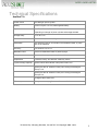
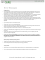
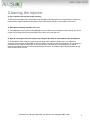
ACUSHOT NEEDLE-FREE
Owner’s Manual
Print Version - Last Updated – July 31, 2010
75 Henlow Bay, Winnipeg, Manitoba, Canada R3Y 1G4 Copyright 2008 - 2010
1 OWNERS’S MANUAL
Table of Contents
Owner’s Manual .............................................................................................................................................. 1 Table of Contents............................................................................................................................................. 2 Technical Specifications ................................................................................................................................... 3 Error Messages ................................................................................................................................................ 4 Cleaning the injector ........................................................................................................................................ 5 Battery Preparation ......................................................................................................................................... 6 Injector Preparation......................................................................................................................................... 7 Installing the Syringe clip or bottle holder ........................................................................................................ 8 Preparing to remove the air from the injector.................................................................................................. 9 Preparing to remove the air from the injector with the remote hand piece installed..................................... 10 Install Medication .......................................................................................................................................... 11 Installing the Battery...................................................................................................................................... 12 Starting the injector and going through the menus ........................................................................................ 13 Locking and unlocking the display .................................................................................................................. 14 Dose Tracking……………………………………………………………………………………………………………………………………………….15 Shutting the injector Off……………………………………………………………………………………………………………………………….16 Power Cylinder Selection Charts..................................................................................................................... 17 Precautions............................................................................................................Error! Bookmark not defined. Basic Package Includes ................................................................................................................................... 19 Accessories .................................................................................................................................................... 20 Install the Remote Injection Extension ........................................................................................................... 21 Injector Parts ................................................................................................................................................. 23 Maintenance Schedule................................................................................................................................... 24 Trigger Plate and Power Cylinder cleaning procedure ……….............................................................................25 User Feedback & Monitoring System ............................................................................................................. 26 AcuData information...................................................................................................................................... 29 Injecting an Animal ........................................................................................................................................ 30 Cleaning or Changing an Orifice...................................................................................................................... 31 Rinsing the injector after use ......................................................................................................................... 32 Removing the Injection Barrel........................................................................................................................ 33 Storing the Injector ........................................................................................................................................ 34 Hands Free Stand Assembly…………………………………………………………………………………………………………………………. 35 Contact .......................................................................................................................................................... 42 75 Henlow Bay, Winnipeg, Manitoba, Canada R3Y 1G4 Copyright 2008 - 2010
2 Technical Specifications
AcuShot™ A
Power source
Inert Nitrogen power cylinder
Battery
Lithium Polymer 14.8 Volt, Rechargeable battery
Injection abilities
Intra/Trans-Dermal, Subcutaneous, Intramuscular
Depending on strength of power cylinder and dosage selected
Dosage ability
0.2 cc to 2.5 cc
Materials
Stainless Steel, Aluminum, Engineered Resin Compounds
Sterilization
Boil Stainless parts for 20 minutes in Demineralised water, or place
then in an Autoclave
Accuracy
Plus or Minus 1% at 1 cc
Medication feed
Direct from Medication bottle or plastic syringe
Weight
Injector with battery and power cylinder - 7 lbs
Applications
Livestock, Poultry, Zoo animals, Veterinary Clinics
Injector Storage Capacity
Injector without the extension hand piece holds 2.5ml
Injector plus the 40” extension holds (not including the 90 degree
elbow) 7.5ml
Injector plus the 48” extension holds (not including the 90 degree
elbow) 8.5ml
90 degree elbow holds .5ml
Warranty
One year warranty against manufacturers defects
75 Henlow Bay, Winnipeg, Manitoba, Canada R3Y 1G4 Copyright 2008 - 2010
3 Error Messages
Plugged Orifice
•
Occasionally debris can enter the injection barrel causing a plugged or partially plugged orifice. Take the small
wire included with the injector and push it through the orifice from the front of the injection tip. This should clear
the pathway. You may need to remove the orifice and clean it thoroughly from both ends
•
Repeated dry shots can cause damage to the piston O ring causing plugged orifices. If you experience repeated
dry shots, replace the piston O ring, clean or replace the orifice as well as debris in the injection barrel,
reassemble and insure proper priming has taken place. Now proceed with your injections
•
Check to make sure the back plate has been re installed after inserting the pink, green and blue power cylinders.
Failure to install the backing plate with these cylinders can cause the injector to report a false plugged orifice error
message. You should not re install the backing plate when using the red and yellow cylinders.
Dry Shot
•
Dry shot indicates that air has entered the system
•
Check to see if you’ve run the supply bottle empty
•
Check all connections to insure no air is getting in the system. Sometimes the 90 degree elbow attached to the
injector for the extension hand piece can loosen slightly during use.
•
Check and tighten the connections often to insure no air is allowed into the system.
•
Check to see if the bottle spike is plugged causing a vacuum in the system which could restrict the flow through to
the injector
•
Check to see if there is too much negative pressure in the bottle creating a vacuum. Reprime injector and
extension hand piece if applicable
•
During the priming procedure Dry Shots are also possible if a substantial amount of air bubbles are trapped in
the supply hose. If you experience a Dry Shot error message during priming, clear the error message and take a
few more shots and the message should not return. If this doesn’t solve the issue you should review all of the
suggestions listed in Dry Shot
Battery Voltage Low/ Battery Voltage Critical
•
Voltage Low message indicates that the battery is low and will require charging shortly.
•
Critical Voltage indicates that the battery requires recharging immediately
Verify Cylinder
•
Indicates that you have inserted a different power cylinder than you selected during the start up procedures
•
Can also indicate that the cylinder has been degassed rendering it useless due to multiple dry shots.
75 Henlow Bay, Winnipeg, Manitoba, Canada R3Y 1G4 Copyright 2008 - 2010
4 Cleaning the injector
Q: Can I submerse the injector during cleaning?
A: No! Similar to cordless tools, the AcuShot is not designed to be submersed in any liquid solution. A damp rag
can be used to wipe the exterior of the injector. Read “Cleaning the Injector” in the AcuShot user manual.
Q: What type of cleaning solutions can I use?
A: A mild detergent such as dish washing detergent can be used to clean the exterior of the AcuShot. This same
mixture can be used while flushing the injector with warm or hot water after use.
Q: How do you properly clean the injector after using the penicillis or other products with oil adjutants?
A: It is possible to clean simply by shooting water through and the pressure does clean it very well but for
unusually sticky products, disassemble the barrel assembly and boil all of the removable parts. The inside of the
extension hose is made of Teflon which is very easy to clean. The steel tip on the hand piece can also be
removed and boiled. The barrel in the hand piece does not contain any additional piece therefore simply rinsing
with hot water will clean it out
75 Henlow Bay, Winnipeg, Manitoba, Canada R3Y 1G4 Copyright 2008 - 2010
5 AcuShot Startup Procedure
Battery Preparation
1. Plug battery into the battery charger
2. Plug the power adapter into the battery charger
When charging is completed the battery charger will begin to beep on and off and the display will alternate
between three screens; #1. "Battery charge complete", #2. a screen showing voltage in each battery cell, and
#3 a screen showing the amperage in each cell.
The voltage of each cell should be 4.20v and the amperage value will range from ~0.04 to ~0.40. The
beeping or chirping sound should be consistent and should not stop, if it does stop, you should leave the
battery connected and continue the charging.
The battery MUST BE UNPLUGGED AND REMOVED from the unit
before being plugged into charger.
75 Henlow Bay, Winnipeg, Manitoba, Canada R3Y 1G4 Copyright 2008 - 2010
6 Injector Preparation
1. Select power cylinder from chart (Chart attached)
2. Remove cylinder "T" key
4. Unlock trigger.
6 – B. For Red and Yellow cylinders
leave the backing plate open
and re-install the “T” Key
3. Pull out and swing away cylinder backing plate
5. Insert power cylinder
6-A. For Pink, Green & Blue
cylinders. Swing the cylinder
backing plate into original position
and re-install the “T” key
7.Lock Trigger
Remember to return the trigger lock to its original position after inserting the Power Cylinder.
75 Henlow Bay, Winnipeg, Manitoba, Canada R3Y 1G4 Copyright 2008 - 2010
7 Installing the Syringe clip or bottle holder
Line up the syringe clip or the bottle holder base with the holder on the injector
Gently push it into place making sure that it is in line with the clips on the base
To release the syringe clip or the bottle holder, press the small tab downward
to release the lock, slide the syringe holder or bottle holder off of the injector.
75 Henlow Bay, Winnipeg, Manitoba, Canada R3Y 1G4 Copyright 2008 - 2010
8 Preparing to remove the air from the injector
Using one of the 60 cc syringes provided,
fill the syringe with sterile "injectable” water
Install a female luer lock fitting on the end
of a 4 to 5 cm piece of tubing and a male fitting
on the other end. Install onto the syringe.
BEFORE CONNECTING THE SYRINGE TO THE INJECTOR
REMOVE ALL THE AIR FROM THE SYRINGE AND HOSE
Connect the hose to the fitting on the barrel
of the injector (one quarter turn to lock).
Snap the syringe into syringe holder.
Removing the air from the injector
1. Hold the injector with the barrel pointing straight upwards
2. When using the hand piece, hold the hand piece higher than the injection barrel
3. Push plunger on the syringe
• This will remove the air from the injection barrel and the extension hose
(This is extremely important!!!!!!!)
• Tap the barrel firmly but gently and push additional water through the barrel and hose
• Keep an eye on the end of the hand piece (orifice) where the water is coming out.
• If air is present, the stream of water will be interrupted by air and will "sputter" intermittently. To
verify air is no longer present, stop pressing on the syringe plunger and watch to see that the
stream of water coming out of the orifice also stops immediately. if water does not stop flowing
immediately, then air may still be present in the system and the injector may not function properly.
• If when you stop pushing on the syringe plunger the water immediately stops exiting the orifice tip
on the hand piece then you have successfully removed all of the air
It is necessary to start the injector and fire 4 to 5 shots at 1.0 cc using the water supply to work out any
small remaining air pockets.
75 Henlow Bay, Winnipeg, Manitoba, Canada R3Y 1G4 Copyright 2008 - 2010
9 Preparing to remove the air from the injector
with the remote hand piece installed
1. Connect the hose to the fitting on the barrel
of the injector (one quarter turn to lock)
2. As shown on the right, with a firm grip on the
remote hand piece, leave the injector hang.
Using the syringe, slowly push water filling the
extension and forcing the air out.
3. Push plunger on the syringe
• This will remove the air from the injection barrel and the extension hose
(This is extremely important!!!!!!!)
• Tap the barrel firmly but gently and push additional water through the barrel and hose
• Keep an eye on the end of the hand piece (orifice) where the water is coming out.
• The stream of water will be interrupted by air and will "sputter" intermittently when air is still present, stop
pressing on the syringe plunger and watch to see that the stream of water coming out of the orifice also
stops immediately, if not then air is still present in the system and the injector will not function properly.
• You will know you have successfully removed all the air, if when you stop pushing on the syringe plunger
the water immediately stops exiting the orifice tip on the hand piece
• The extension hose and hand piece hold about 7.5 cc (40 inch) or 8.5 cc (48 inch) of liquid.
It is necessary to start the injector and fire 4 to 5 shots at 2.0 cc using the water supply to work out any
small remaining air pockets.
With all the air removed, and your medication supply connected, it will be necessary to shoot either 5 –
2cc shots, or 9 - 1cc shots before you start to use the injector. These shots replace the water in the
extension used for removing the air with the vaccine you will be injecting.
75 Henlow Bay, Winnipeg, Manitoba, Canada R3Y 1G4 Copyright 2008 - 2010
10 Install Medication
Three options for supplying medication can be used
1. Syringe, 2. Bottle holder, or 3.Extension hose to injector
Option 1
Option 2
Option 3
1. As shown above, draw vaccine into syringe or connect to vaccine supply bottle.
Once supply is full or connected, remove all air bubbles from supply hose.
When using a bottle, a small syringe can be used with the adapter supplied to remove the air.
2. Connect luer lock fitting from either syringe, bottle holder or extension hose to injector.
Again verify no air bubbles are trapped in the supply hose.
75 Henlow Bay, Winnipeg, Manitoba, Canada R3Y 1G4 Copyright 2008 - 2010
11 Installing the Battery
1. Open the battery door
3. Insert the battery into the battery compartment
as shown above, then tuck the wires in after
2. Connect the battery plug
4. Close the battery door
75 Henlow Bay, Winnipeg, Manitoba, Canada R3Y 1G4 Copyright 2008 - 2010
12 Starting the injector and going through the menus
ALWAYS PRESS THE UPPER LEFT BUTTON TO MOVE TO NEXT SCREEN
**Note the screen number on the bottom, right hand side of each screen. This number can be used as a reference for
translation documents. The (# ) beside each description indicates the screen number for that screen.
1. Press the RED button to start
3. Verify battery condition (#2)
5. Select the supply container size (#6)
7. Daily shot counter page (#8)
2.
Select user number (#1)
4. Confirm power cylinder selection (#4)
6. Select the dose you will be injecting (#7)
- Press the lower right hand button to reset
75 Henlow Bay, Winnipeg, Manitoba, Canada R3Y 1G4 Copyright 2008 - 2010
13 - Or press the upper left button to skip
ALWAYS PRESS THE UPPER LEFT BUTTON TO MOVE TO NEXT SCREEN
8. Injector is now ready to be armed (#20)
9. After arming the main screen will appear (#9)
Locking and unlocking the display
(#9)
To lock the display press and hold the upper left hand button for 2 seconds.
You will see the regular flashing arrows disappear and 4 X’s appear beside the buttons.
WHEN THE SCREEN IS LOCKED, THE DOSE OR ANY OTHER SETTINGS CANNOT BE CHANGED
UNTIL THE DISPLAY IS UNLOCKED.
This prevents accidental changes to the dosage while the injector is being used.
To unlock the display, press and hold the upper left hand button again for 2 seconds.
You will see the 4 X’s disappear and the regular flashing arrows will reappear.
75 Henlow Bay, Winnipeg, Manitoba, Canada R3Y 1G4 Copyright 2008 - 2010
14 DOSE TRACKING FEATURE
•
While going through the start up menu, a “Dose Tracking” menu screen will appear. You will be able to
select a supply size of medication supply that will be used. Example 50cc, 100 cc, 250cc, etc.
WHEN USING A SMALLER SUPPLY SIZE
•
When using a smaller supply size in the range of 25cc to 200cc, the
injector will begin to warn you when 6 shots are remaining, and will stop
re-arming when 3 shots remaining.
•
At this point, you can press the key indicated by the arrow on the
screen to continue, this will allow you to do one shot at a time.
•
To reset the Dose Tracking after the supply has been changed simply
press the RED button to go to the Dose Tracking screen
WHEN USING A LARGER
SUPPLY SIZE
•
(#24)
When using a larger supply size from 250cc to 1000cc, the injector will begin to warn you when 10 shots
are remaining, and will stop automatically rearming when 3 shots remaining.
•
At this point, as before, you can press the key indicated on the screen to continue with one shot at a time
until the supply is completely empty.
RESETTING
•
(#24)
(#23)
When 3 to 5 shots are remaining, (depending on original supply size chosen) you have the choice to
“Ignore” or “Reset”. If you choose “Ignore” you will be able to perform one injection at a time, and will
need to press “Ignore” before each injection
•
Once you replaced the supply with a full bottle, you simply press the reset button and the dose tracking
will be reset. You will have the chance to change the selection of the bottle size at this time.
75 Henlow Bay, Winnipeg, Manitoba, Canada R3Y 1G4 Copyright 2008 - 2010
15 Shutting the injector OFF
(#14)
Press and hold the RED button
The screen will read “FIRE LAST SHOT”
Very important to shut the injector OFF using
“Last Shot” so that it is NEVER stored ARMED.
75 Henlow Bay, Winnipeg, Manitoba, Canada R3Y 1G4 Copyright 2008 - 2010
16 Power Cylinder Selection Charts
Pigs
Depth of injection
Intradermal
New Born
Piglet
Pig
Finisher
Sow
1 to 7 Days
Up to 2 weeks
Up to 60 lbs
60 lbs to market weight
Pink
Green
Blue
Blue/Red
Red/Yellow
Cattle
Pink
Green
Blue
Red
Red/Yellow
Intramuscular
Pink/Green
Green/Blue
Red
Red/Yellow
Yellow
Depth of injection
Intradermal
Calves
Feeder cattle**
Subcutaneous
Up to 6 months
Density of hair must be
considered
Dairy Cows***
Subcutaneous
Intramuscular
Blue/Red
Blue/Red
Red
Red
Blue/Red
Red/Yellow
Red/Yellow
Yellow
Red/Yellow
** Feeder cattle: An animal with a heavy coat of hair will likely have a thicker hide. In such cases,
the higher power cylinder should be used. Due to a very wide variety of environmental conditions
and cattle breeds, an initial trial with recommended power cylinder is suggested and close
inspection of injection site needed.
*** Dairy cows: Similar to other species, younger animals can sometimes be injected with a lower
powered cylinder.
Sheep
Depth of injection
Intradermal
New born Lamb
Lamb
Sheep
Up to two weeks
Up to 6 months
Over 6 months (Ewe, Ram)
Green
Blue
Blue/Red
Subcutaneous
Green
Blue
Red
Intramuscular
Green
Blue/Red
Red/Yellow
75 Henlow Bay, Winnipeg, Manitoba, Canada R3Y 1G4 Copyright 2008 - 2010
17 Precautions
Keep hands and finger clear of the injectors tip.
Do not Dry Fire the injector.
Do not use Alcohol or Ammonia based cleaners at any time.
Do not submerse the injector or the hand piece under water.
Do not point the injector at anything you do not intend to inject.
Avoid shooting the injector into the air.
** Some vaccines or medication can be harmful if sprayed into the air and the mist is inhaled.
Always use a large very dense sponge or large rolled up rag to fire the injector into.
**Never hold the large rolled up rag in your hand, it is possible that the injection will pass through the rag.
If the injection passes through the rag, use a larger rag to capture the injection.
After using clean water to remove the air from the remote hand piece and extension, and connecting your
vaccine or medication supply, it is very important to fire either 5 – 2cc shots, or 9 - 1cc shots to replace
the water used for removing the air with the vaccine or medication you will be injecting.
You do not want to inject water into any animals.
**When using the remote hand piece extension, it is possible to remove the vaccine or medication supply
and replace it with clean water, and inject the 7.5 – 8.5 cc of vaccine or mediation in the extension so that
no vaccine or medication is lost.
After the last 7.5 – 8.5 cc of vaccine or medication is used, fire the injector 5 to 10 times into a large rolled
up rag placed in a sink, to thoroughly rinse out the extension and remote hand piece.
75 Henlow Bay, Winnipeg, Manitoba, Canada R3Y 1G4 Copyright 2008 - 2010
18 Basic Package Includes
Injector
Handle and removal key
Supply hose, clamps and connectors
Disposable syringes
Power cylinder
Cylinder removal tool
Extra orifice, fuses, cleaning wire, O rings, etc.
2 wrenches
2 batteries
Battery charger
75 Henlow Bay, Winnipeg, Manitoba, Canada R3Y 1G4 Copyright 2008 - 2010
19 Accessories
(Injector displayed with 2 optional accessories)
Hands Free Stand
Remote Extension with Hand Piece
Power Cylinders
75 Henlow Bay, Winnipeg, Manitoba, Canada R3Y 1G4 Copyright 2008 - 2010
20 Install the Remote Extension
Remove the barrel trigger sleeve by pinching it near the
injector and pulling it away from the injector
Loosen barrel nut and remove it. This will reveal the
valve and spring.
Remove the valve and spring and set them aside.
Using the wrench provided, unscrew
orifice and remove it completely.
Reinstall the barrel nut ONLY.
WITHOUT THE VALVE AND SPRING
and tighten the barrel nut.
Gen II Piston
with two back-up rings
75 Henlow Bay, Winnipeg, Manitoba, Canada R3Y 1G4 Copyright 2008 - 2010
21 Install extension adapter and tighten
Install the extension, and tighten
Locate the plug connection on the side
of the injector and insert the yellow cable.
You will now need to remove all of the air from the remote hand piece and extension, before you begin using the
injector to perform injections.
SEE SECTION: (Preparing to remove the air from the injector with the remote hand piece installed)
75 Henlow Bay, Winnipeg, Manitoba, Canada R3Y 1G4 Copyright 2008 - 2010
22 Injector Parts
Top one-way valve
Barrel assembly
Top Luer
Connector
O-Ring #4
Top Valve
Top Valve Spring
Bottom
Seat
Injection
piston
Barrel Nut
O-Ring #1
Gen II Piston
with two back-up rings
O-Ring #5
Barrel
O-Ring #3
O-Ring #2
Front
Valve
O-Ring #4
Front Valve
Spring
75 Henlow Bay, Winnipeg, Manitoba, Canada R3Y 1G4 Copyright 2008 - 2010
Orifice
23 Maintenance Schedule
•
•
•
Attach a clean supply of water to the injector (to replace the vaccine or medication supply) and shoot the
injector several times to rinse the barrel, hose and remote extension hand-piece thoroughly.
o Hot water and mild detergent can be used to flush through the system for clean up after sticky or
oily products. This can be done through the injector and the hand-piece if applicable
o When using the remote hand-piece, it is important to regularly rinse the barrel trigger, as it can
become sticky
DO NOT SUBMERGE THE INJECTOR OR REMOTE HAND-PIECE UNDER WATER
Disconnect the battery from the injector and charge it.
o The battery should be allowed to cool down (5 – 10 minutes) before recharging
Weekly maintenance:
•
•
•
•
•
Replace the injection piston o-ring #1 (see owner’s manual for instructions)
Rinse and clean the barrel, barrel nut, front valve, and front valve spring
o (this is also a good time to boil these parts in de-mineralized water for 20 minutes if you want to
sterilize them, but it is not required)
Remote Hand-Piece
o Remove the barrel trigger, rinse and clean
o Remove the orifice, barrel nut and the front valve. Rinse and clean
Remove the top one-way valve, and disassemble it to thoroughly rinse and clean the top valve and top
valve spring (in the owner’s manual you will find an enlarged picture that identifies all of the barrel
assembly and top one-way valve parts)
Once the unit is reassembled, follow the instructions found in “Air Removal Procedure” in the owner’s
manual before you begin injecting vaccines.
Monthly maintenance:
•
•
Do the following in addition to the weekly maintenance schedule:
o Replace barrel o-ring #2, front valve o-ring #3, orifice o-ring #4, and bottom seat o-ring #5
o The back-up rings should be inspected but only replaced if visible broken, these back-up rings
should only require replacement every six months.
Inspect top luer connector o-ring # 4 and replace only as needed
Trigger Plate and Power Cylinder cleaning
75 Henlow Bay, Winnipeg, Manitoba, Canada R3Y 1G4 Copyright 2008 - 2010
24 Power cylinders are compressed and released numerous times during normal injector use. An oily film
will often begin to form on the Power Cylinders Rod and the Injectors Trigger Plate. Excess oil build up
should be removed occasionally by using a clean dry cloth.
NEVER USE ANY LIQUIDS OR SOLVENTS FOR CLEANING THE ROD.
Excessive cleaning of the power cylinder may remove all of the oil and can impede the proper operation
of the power cylinder.
Supplies needed:
1. A piece of clean dry cloth
(approx. 2.5cm wide and 30cm long)
2. A length of stiff wire approx. 30 cm long
(a piece of metal coat hanger works well)
Using the clean dry cloth, wipe the
Rod of the Power Cylinder
DO NOT USE ANY SOLVENTS
With the Power Cylinder removed and the
backing plate swung open, look into the injector
and you will see two holes that may be slightly
off center from one another. The first hole is an
alignment bushing the second if the Trigger Lock
Plate. It is possible that some oil from the
Power Cylinder was deposited here.
Using a strip of clean dry cloth, start at one
end of the stiff wire and twist the cloth around
the wire as shown above. Bending the other
end of the wire will provide a handle.
Insert the stiff wire and dry cloth into the
injector where the Power Cylinder is usually
inserted and move it back and forth to wipe the
inside of the two holes. You may want to
remove the cloth and wire and re-twist it using
a clean section of cloth and repeat the process.
75 Henlow Bay, Winnipeg, Manitoba, Canada R3Y 1G4 Copyright 2008 - 2010
25 User Feedback & Monitoring System
Your AcuShot injector monitors every injection cycle and takes several readings during each cycle. These
readings are analyzed and recorded in the injector memory. If a problem should occur during a cycle the injector
will warn the user by beeping and displaying a message on the screen.
If you are using the remote hand piece, the LED light on the hand piece will flash red.
Warning Messages
Plugged Orifice
•
Occasionally debris can enter the injection barrel causing a plugged or partially plugged orifice. Take the
small wire included with the injector and push it through the orifice from the front of the injection tip. This
should clear the pathway. You may need to remove the orifice and clean it thoroughly from both ends.
•
Below are the screens that the injector will display if a plugged orifice is detected. Simply follow the screen
prompts to correct the problem.
(#15)
(#18)
(#19)
•
Repeated dry shots can cause damage to O ring #1 causing plugged orifices. If you experience repeated
dry shots, replace the O ring #1, clean or replace the orifice as well as debris in the injection barrel,
reassemble and insure proper priming has taken place. Now proceed with your injections
•
Check to make sure the backing plate has been re installed after inserting the pink, green and blue power
cylinders. Failure to install the backing plate with these cylinders can cause the injector to report a false
plugged orifice error message. You should not re install the backing plate when using the red and yellow
cylinders.
75 Henlow Bay, Winnipeg, Manitoba, Canada R3Y 1G4 Copyright 2008 - 2010
26 Dry Shot
•
Dry shot indicates that air has entered the system
•
Check to see if you’ve run the supply bottle empty
•
Check all connections to insure no air is getting in the system. Sometimes the 90 degree
elbow attached to the injector for the extension hand piece can loosen slightly during use.
•
Check and tighten the connections often to insure no air is allowed into the system.
•
Check to see if the bottle spike is plugged causing a vacuum in the system which could
restrict the flow through to the injector
•
Check to see if there is too much negative pressure in the bottle creating a vacuum.
Reprime injector and extension hand piece if applicable
•
During the priming procedure Dry Shots are also possible if a substantial amount of air
bubbles are trapped in the supply hose. If you experience a Dry Shot error message
during priming, clear the error message and take a few more shots and the message
should not return. If this doesn’t solve the issue you should review all of the suggestions
listed in Dry Shot
•
Below are a series of screens that the Injector will display if a “Dry shot” is detected. You
can follow the screen prompts and the injector will help with re-priming the injector, barrel
and extension hose, or you can re-prime using a syringe as per the initial priming method.
(#17)
(#31)
(#27)
(#28)
(#29)
75 Henlow Bay, Winnipeg, Manitoba, Canada R3Y 1G4 Copyright 2008 - 2010
(#30)
27 **ALWAYS REMEMBER TO POINT THE INJECTOR’S BARREL UPWARDS AND HOLD THE EXTENSION
HOSE AND HAND PIECE WELL ABOVE THE INJECTION BARREL WHEN RE-PRIMING**
***AIR IS LIGHTER THAN WATER, IF THE INJECTOR IS POINTING DOWNWARDS, THE AIR WILL REMAIN
TRAPPED IN THE INJECTORS BARREL***
Battery Voltage Low/ Battery Voltage Critical
“Battery critical” message indicates that the
battery is low and will require charging
shortly.
This will result in the injector
“Shutting down” immediately.
(#13)
(#14)
•
This indicates that the battery requires recharging immediately. Failure to properly charge battery can lead
to a swelling of the battery leaving the battery ineffective for use
•
Never store battery if it is not fully charged!!
Verify Cylinder
•
Indicates that you have inserted a different power cylinder then you
selected during the start up procedures
•
Can also indicate that the cylinder has been degassed rendering it
useless due to multiple dry shots.
(#22)
75 Henlow Bay, Winnipeg, Manitoba, Canada R3Y 1G4 Copyright 2008 - 2010
28 AcuData information
The Injector’s monitoring system records and maintains the information from the last several thousand
injections.
Information recorded includes items such as;
•
Shot number
•
Power cylinder used
•
Dosage given
•
Any alerts that may have occurred
With the appropriate software, this information can be downloaded from the injector to a computer to allow for
review.
This information is useful in many ways to see how the injector is performing and if it is being used correctly.
The information is stored in a format allowing download into an Excel spreadsheet.
Detailed AcuData instruction document available separately.
75 Henlow Bay, Winnipeg, Manitoba, Canada R3Y 1G4 Copyright 2008 - 2010
29 Injecting an Animal
Always use firm pressure to ensure good skin contact.
Place and Shoot
Step 1
Press the injectors’ barrel tip on the animal.
Step 2
Press the finger trigger.
The injector will be triggered and will immediately start to recharge for the next injection.
Rapid Fire
Step 1
Press and hold the finger trigger.
Step 2
Press the injector barrel tip on the animal.
The injector will be triggered and will immediately start to recharge for the next injection.
75 Henlow Bay, Winnipeg, Manitoba, Canada R3Y 1G4 Copyright 2008 - 2010
30 Cleaning or Changing an Orifice
The injector should be OFF and the Last Shot fired.
Remove the barrel trigger sleeve by pinching it
near the injector and pulling it away from the injector
Gently tap orifice on hard surface to free the obstruction.
If the orifice is still plugged, use the fine wire provided
and push it through the orifice from the front.
Repeat Step 3 and 5 until the orifice is clear.
Using the wrench provided, loosen the
orifice and remove it completely.
Rinse the orifice and try to look through
the hole in front of a light, it must be
clear.
Reinstall the orifice and tighten it.
Reinstall the barrel trigger.
(The same procedure can be done when using extension hand piece.)
75 Henlow Bay, Winnipeg, Manitoba, Canada R3Y 1G4 Copyright 2008 - 2010
31 Rinsing the injector after use
Remove whatever vaccine or medication supply that was used
Install clean water supply
It is possible to use a very mild dish washing detergent in the water to help with degreasing especially when using an
oil based vaccine. You can also use a mild disinfecting solution. If a mild disinfecting solution is used, you must insure
that you flush the disinfecting solution very well using a lot of water; otherwise you may run the risk that the disinfectant
will affect the next vaccine or medication that you will be injecting.
Force water through by pressing plunger on syringe.
5 to 10 shots should be fired into a large rolled up rag placed in a sink using clean water to insure thorough rinsing.
**Never hold the large rolled up rag in your hand, it is possible that the injection will pass through the rag. If
the injection passes through the rag, use a larger rag to capture the injection.
**Do not fire the injector into the air, as some vaccines or medication can be harmful if a mist is inhaled.
**When using the remote hand piece extension, it is possible to remove the vaccine or medication supply and
replace it with clean water, and inject the 7.5 cc (40 inch) 8.5 cc (48 inch) of vaccine or mediation in the
extension so that no vaccine or medication is lost.
After the last 8.5 cc of vaccine or medication is used, fire the injector 5 to 10 times into a large rolled up rag
placed in a sink, to thoroughly rinse out the extension and remote hand piece.
75 Henlow Bay, Winnipeg, Manitoba, Canada R3Y 1G4 Copyright 2008 - 2010
32 Removing the Injection Barrel
The injector should be turned OFF.
Remove the barrel trigger sleeve.
Turn the barrel until you reach
the end of the thread.
Using the wrench provided,
loosen the barrel.
Then pull the barrel off.
This will reveal the injection piston.
75 Henlow Bay, Winnipeg, Manitoba, Canada R3Y 1G4 Copyright 2008 - 2010
33 Storing the Injector
The injector should be turned OFF, and the last shot has been fired.
Make sure the injector is clean and that you have rinsed the barrel and or the remote extension hand piece very
well with clean water.
The injector body
Use soapy water and wipe the injector clean.
DO NOT place the injector under running water.
The injection barrel
Disconnect medication supply.
DO NOT use alcohol; it will deteriorate the injector's o-rings.
Using sterile water and a syringe connect the syringe to the injector’s barrel and force the water through the
barrel and orifice until all medication is flushed out. Same procedure as “Removing the air from the injector”.
You can also fire the injector into a rolled up rag or very dense foam 3 or 4 times.
This will thoroughly flush the barrel and orifice.
***Always store the injector with the clean syringe and water connected to the barrel***
Never dry fire the injector.
Keep the injector in a warm and dry area.
Make sure a clean syringe with sterile water is connected to the injectors barrel at all times.
This will help keep dust and dirt out of the injection barrel and insure the injector remains primed and ready for
use.
**Never store the injector with vaccines,
medications, or supplements loaded in the barrel**
**Always make sure the injector is OFF and the last shot has been fired
AND THE BATTERY HAS BEEN UNPLUGGED**
75 Henlow Bay, Winnipeg, Manitoba, Canada R3Y 1G4 Copyright 2008 - 2010
34 Handsfree Stand Assembly
In the picture above is what will all be needed to assemble the Handsfree Stand. Any lubricant will be fine.
(Lubricant and Allen Key Not Included)
75 Henlow Bay, Winnipeg, Manitoba, Canada R3Y 1G4 Copyright 2008 - 2010
35 Apply lubricant to all the screws. This will allow easier
threading when assembling.
Using the Hex Drive Fasteners provided, join the parts as shown in the image above.
75 Henlow Bay, Winnipeg, Manitoba, Canada R3Y 1G4 Copyright 2008 - 2010
36 Insert the same fasteners at the sides of the base, as shown in the images above.
Assemble the following parts as shown in the front or rear hole, using only one
fastener per side.
75 Henlow Bay, Winnipeg, Manitoba, Canada R3Y 1G4 Copyright 2008 - 2010
37 Insert fastener on the opposite side and opposite hole. Use the Allen key to tighten the fasteners.
Install the two cone shaped, “counter sunk” screws to hold the round base in place similar to the original
instructions.
(As shown in the picture)
Use the new Hex wrenches provides to tighten the two screws firmly.
75 Henlow Bay, Winnipeg, Manitoba, Canada R3Y 1G4 Copyright 2008 - 2010
38 Install three of the large screws provides to fasten the round plate to the large metal base. You can select any
three holes that line up with the fasteners in the large base in order to obtain the placement of the injector
holder & and Bump switch (Red Button).
It can be rotated to face in any direction t to better suit many possible ways of using the Handsfree stand.
Please always insure that the three fasteners can be installed and tighten firmly to insure that the Bump switch
(Red Button) is held firmly in place.
Now, to attach the button to it’s mounting plate, insert
two Phillips Head Machine Fasteners and nut. Only two
are needed at opposite corners.
75 Henlow Bay, Winnipeg, Manitoba, Canada R3Y 1G4 Copyright 2008 - 2010
39 Next, to attach the remaining part to the button mounting plate, align the holes as indicated and insert the
Hex Drive Fastener in the bottom hole first.
Insert fastener into top hole, then adjust the button to suit your needs. Remember to fasten with the
Allen Key.
Finally, insert fasteners like the image above to attach the button to the rest of the stand
75 Henlow Bay, Winnipeg, Manitoba, Canada R3Y 1G4 Copyright 2008 - 2010
40 And here is the Handsfree Stand, fully assembled.
Installing the injector on the Handsfree stand
After installing the handle on the injector, slide it on to the handsfree stand and plug the yellow wire in
to the side of the injector as shown above.
75 Henlow Bay, Winnipeg, Manitoba, Canada R3Y 1G4 Copyright 2008 - 2010
41 Contact
AcuShot Inc.
75 Henlow Bay, Winnipeg, Manitoba, Canada R3Y 1G4
Technical Support - 1-204-744-2065
Marketing - 1-204-746-4411
Fax -1-204-744-2696
Email: [email protected]
75 Henlow Bay, Winnipeg, Manitoba, Canada R3Y 1G4 Copyright 2008 - 2010
42