1
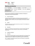
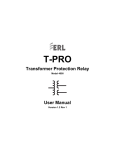
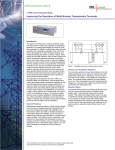
People with Passion
B-PRO Bus Protection Relay
Best in Class Technology
Bus Differential Function
Settings
Power System Focus
Monitor and Manage your Power System with Ease.
B-PRO Bus Protection Relay
Bus Differential Function Settings
Introduction
The B-PRO Bus Protection Relay provides low-impedance differential protection for transmission and distribution buses, for up to 6
three-phase inputs. The B-PRO is a per-unit based relay, meaning all secondary currents entering the relay are converted to per-unit
values for protection calculations. Choosing the correct per-unit base for the current permits the development of standard protection
settings that work for most bus protection applications. The resulting settings method only requires 2 calculations to implement.
The settings described in this technical note will provide a good balance between dependability and security of the protection system. This method also assumes the CTs have burdens within their ratings, and that the measured secondary current by the CTs is
between 0.2 A and 15 A secondary.
Bus Differential (87B) Protection Function Characteristic
The operating characteristic of the 87B function is shown in Figure 1. IOmin is the minimum operating current for fault detection. IRs
is the setting for the breakpoint between the region of slope S1 and the region of slope S2. IRs is normally used as the upper limit of
the “load range”, or the protection zone used to detect bus faults during normal load conditions. The S2 region is therefore used for
protection during through-fault events, where CT measurement errors can be quite large. The High Current Setting is an un-restrained differential element. Settings are described more completely in the B-PRO instruction manual.In addition to this operating
characteristic, the B-PRO includes a CT Saturation Detection algorithm that correctly identifies CT saturation due to external faults,
and blocks the differential element from tripping.
IO
High
Curr ent
Setting
Op er ate
Restrain
S2
IO min
S1
IR
IR s
Figure 1: 87B operating characteristic
In addition to this operating characteristic, the B-PRO includes a CT Saturation Detection algorithm that correctly identifies CT saturation due to external faults, and blocks the differential element from tripping.
While performing setting calculations for the B-PRO, the IO operate current is calculated by the equation:
IO = I 1+ I 2+ I 3+ I 4+ I 5+ I 6 A per unit
The restraint current IR calculation is:
I1 + I 2 + I 3 + I 4 + I 5 + I 6
IR =
2
A per unit
Our multi function relays and recorders provide smart solutions to your protection, monitoring and
control needs.
www.erlphase.com
ERLPhase (formerly a division of NxtPhase), is a subsidiary of Easun Reyrolle Ltd with over 60 years of power management expertise.
smart solutions that empower you
smart solutions that empower you
[email protected]
www.erlphase.com
204-477-0591
[email protected]
74 Scurfield Blvd
204-477-0591
Winnipeg, MB
74
Scurfield
Blvd
Canada
R3Y
1G4
Winnipeg, MB
Canada R3Y 1G4
B-PRO Bus Protection Relay
Bus Differential Function Settings
Settings Philosophy
The recommended settings method described in this technical note is simple: choose the MVA Base setting of the relay such that the maximum bus
transfer load current is equal to the IRs setting in per-unit current. All other settings are related to the per-unit base current. The preferred setting for IRs
is 2 per-unit, but there are some applications where a higher value is required. This method ensures that IRs is the upper limit setting for the load range,
provides dependability for normal operating conditions, and provides adequate security for through-fault events.
The basic settings philosophy is to make sure operating and restraint current values (during normal operating conditions) fall in the “load range.” This
means the S1 range accommodates the actual operating current, accounting for the maximum CT measurement error under any load condition. External
fault conditions will be in the S2 or High Current range of the characteristic. Figure 2 describes recommended settings for most bus differential applications.
Figure 2: 87B settings
Settings Method
The clearest way to understand the proposed bus differential settings method is through a specific example. Figure 3 illustrates normal load conditions.
1600 A
2000 A
200 0 A
2000: 5
200 0: 5
52
1500 A
200 0: 5
52
900 A
200 0: 5
52
1200: 5
52
52
138 kV
87B
Figure 3: Bus transfer load
smart solutions that empower you
www.erlphase.com
[email protected]
204-477-0591
74 Scurfield Blvd
Winnipeg, MB
Canada R3Y 1G4
B-PRO Bus Protection Relay
Bus Differential Function Settings
Settings are developed using simple steps:
1. Enter Winding/CT connection information
2. Determine the maximum bus transfer current
3. Choose a value for IRs
4. Calculate the Bus Base MVA
5. Determine the CT Saturation Block Timer
6. Enter settings in the B-PRO
1. Enter Winding/CT Connection Information
Enter Winding and CT connection information to match the specific bus protection application, as in the example of Figure 4.
Figure 4: Winding/CT Connections settings
2. Determine the Maximum Bus Transfer Current
The maximum bus transfer current is going to be based on the CT primary ratings. For the example of Figure 3, there are many load flow configurations
possible, but it is not possible to exceed an inflow of 4000 Apri without exceeding at least one CT rating. Therefore, 4000 Apri is the maximum bus transfer condition for this bus. It is possible, of course, for the maximum bus transfer current to be smaller than the rating limits of the CTs due to other system
constraints.
3. Choose a Value for IRs
The IRs setting determines the break point between the slope S1 and slope S2. The IRs setting is also the upper limit of the “load range” of the B-PRO.
For this recommended settings method, the maximum bus transfer current is equal to IRs in per-unit current. The preferred setting for IRs is 2 per-unit,
which will work for most applications, but IRs can be any whole number 2 or greater. This method ensures the IR restraint current of the B-PRO for maximum bus transfer current is always within the upper limit of the “load range”.
4. Calculate the Bus Base MVA
The B-PRO does not have an explicit setting for the current base, but calculates the current base from the Bus Voltage and Bus Base MVA settings.
Therefore, choosing the base current requires calculating the Bus Base MVA.
Bus Base MVA = 3 × Bus Voltage × Base Current
Maximum bus transfer current = IRs
Base Current =
Maximumbus transfer current ( A pri )
IRs ( A per unit )
smart solutions that empower you
www.erlphase.com
[email protected]
204-477-0591
74 Scurfield Blvd
Winnipeg, MB
Canada R3Y 1G4
B-PRO Bus Protection Relay
Bus Differential Function Settings
For the configuration of Figure 3, the maximum bus transfer current = 4000A, and IRs = 2 per-unit.
Base Current =
4000 A pri
2 A per unit
= 2000 A
Bus Base MVA = 3 ×138 kV × 2000 A = 478 MVA
Enter this amount as a relay setting in System Parameters, as illustrated in Figure 5.
Figure 5: System Parameters settings
The maximum relay setting for the Bus Base MVA in the B-PRO is 1000 MVA. (This setting range will be modified to 10,000 MVA in a future product update). If the calculated Bus Base MVA exceeds this value, choose the next higher whole number value for IRs (3 per-unit in this example), and re-calculate the Bus Base MVA.
5. Determine the CT Saturation Block Timer
The settings method used in this Technical Note assumes the CT Saturation Detector is enabled. When an external fault occurs on a feeder, it can look
like an internal fault if the feeder CTs saturate sufficiently. The “saturation detection algorithm” detects this condition and blocks tripping. It does not block
tripping for CT saturation during an internal fault.
Once the CT Saturation Detector has identified a CT saturation condition, the 87B function is blocked from tripping until the CT Saturation Max Block
timer expires. This setting should be greater than the slowest fault clearing time for any of the feeders connected to the bus. A typical clearing time is 5
cycles, or 2 cycles to recognize the fault and 3 cycles for the circuit breaker to open. The minimum setting of 0.10 seconds provides some safety margin.
6. Enter Settings in the B-PRO
The un-restrained differential High Current Setting should be set at 5 x IRs. For this example, 5 x 2 = 10 per-unit. IOmin is set at 0.25 per-unit, other than
for applications with widely diverse CT ratios. S1 is recommended to be at 25%, and S2 at 50%, as shown in Figure 2.
smart solutions that empower you
www.erlphase.com
[email protected]
204-477-0591
74 Scurfield Blvd
Winnipeg, MB
Canada R3Y 1G4
B-PRO Bus Protection Relay
Bus Differential Function Settings
Widely Diverse CT Ratios
“Widely diverse CT ratios” differ by more than 5-to-1 (for example, 1200:5 and 8000:5). With widely diverse CT ratios, there is a possibility of false tripping
under light load conditions. Consider a case such as Figure 6:
320 A
320 A
= 0. 27 p u
1.3 3 A se c
120 0:5
0 A se c
1200: 5
52
0. 2 A se c
8000: 5
52
52
138 kV
87B
Figure 6: Widely diverse CT ratios
Assume that the base current is chosen in the same way described by this Technical Note. Thus the maximum bus transfer current through this bus is
2400 A, and the base current for the bus differential protection is 2400 A/2 = 1200 A.
When the secondary current of a nominally 5A CT is as small as 0.2 A, there is a possibility that the current may be interpreted as close to zero amps,
due to CT error and A-to-D conversion error. Assuming the worst case, 0.2 amps is interpreted as zero amps by the relay.
Then, for this light load condition the operating current, IO, is perceived as 320 – 0 = 320 primary amps. On a 1200 A base this is 0.27 per-unit, which is
above the recommended setting for IOmin, namely 0.25 per-unit. For this case, it is recommended to set IOmin to 0.4 per-unit in order to prevent possible
false tripping of the bus.
References
[1] B-PRO Bus Protection Relay User Manual Version 1.1 Revision 2, NxtPhase Corporation, Vancouver, BC, Canada; 2000
smart solutions that empower you
www.erlphase.com
[email protected]
204-477-0591
74 Scurfield Blvd
Winnipeg, MB
Canada R3Y 1G4