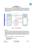
1
Installation and Operation Manual
ProTech® 203
Overspeed Protection System
8200-200, -201, -202, -203, -204, -205,
9907-344, -345
Manual 85205 (Revision F)
WARNING—DANGER OF DEATH OR PERSONAL INJURY
WARNING—FOLLOW INSTRUCTIONS
Read this entire manual and all other publications pertaining to the work to be performed
before installing, operating, or servicing this equipment. Practice all plant and safety
instructions and precautions. Failure to follow instructions can cause personal injury and/or
property damage.
WARNING—OUT-OF-DATE PUBLICATION
This publication may have been revised or updated since this copy was produced. To verify
that you have the latest revision, be sure to check the Woodward website:
www.woodward.com/pubs/current.pdf
The revision level is shown at the bottom of the front cover after the publication number. The
latest version of most publications is available at:
www.woodward.com/publications
If your publication is not there, please contact your customer service representative to get
the latest copy.
WARNING—OVERSPEED PROTECTION
The engine, turbine, or other type of prime mover should be equipped with an overspeed
shutdown device to protect against runaway or damage to the prime mover with possible
personal injury, loss of life, or property damage.
The overspeed shutdown device must be totally independent of the prime mover control
system. An overtemperature or overpressure shutdown device may also be needed for
safety, as appropriate.
WARNING—PROPER USE
Any unauthorized modifications to or use of this equipment outside its specified
mechanical, electrical, or other operating limits may cause personal injury and/or property
damage, including damage to the equipment. Any such unauthorized modifications: (i)
constitute "misuse" and/or "negligence" within the meaning of the product warranty
thereby excluding warranty coverage for any resulting damage, and (ii) invalidate product
certifications or listings.
CAUTION—POSSIBLE DAMAGE TO EQUIPMENT OR PROPERTY
CAUTION—BATTERY CHARGING
To prevent damage to a control system that uses an alternator or battery-charging device, make
sure the charging device is turned off before disconnecting the battery from the system.
CAUTION—ELECTROSTATIC DISCHARGE
Electronic controls contain static-sensitive parts. Observe the following precautions to
prevent damage to these parts.
•
Discharge body static before handling the control (with power to the control turned off,
contact a grounded surface and maintain contact while handling the control).
•
Avoid all plastic, vinyl, and Styrofoam (except antistatic versions) around printed circuit
boards.
•
Do not touch the components or conductors on a printed circuit board with your hands
or with conductive devices.
•
IMPORTANT DEFINITIONS
A WARNING indicates a potentially hazardous situation which, if not avoided, could result in
•
A CAUTION indicates a potentially hazardous situation which, if not avoided, could result in
•
A NOTE provides other helpful information that does not fall under the warning or caution
death or serious injury.
damage to equipment or property.
categories.
Revisions—Text changes are indicated by a black line alongside the text.
Woodward Governor Company reserves the right to update any portion of this publication at any time. Information
provided by Woodward Governor Company is believed to be correct and reliable. However, no responsibility is
assumed by Woodward Governor Company unless otherwise expressly undertaken.
© Woodward 1997
All Rights Reserved
Manual 85205
ProTech 203 Overspeed Protection System
Contents
ELECTROSTATIC DISCHARGE AWARENESS ..................................................III
REGULATORY COMPLIANCE........................................................................ IV
CHAPTER 1. GENERAL INFORMATION ........................................................... 1
Introduction.............................................................................................................1
Description..............................................................................................................1
Applications ............................................................................................................1
References .............................................................................................................2
CHAPTER 2. INSTALLATION.......................................................................... 3
Unpacking...............................................................................................................3
Power Requirements ..............................................................................................3
Location Considerations.........................................................................................3
Shielded Wiring ......................................................................................................3
Plant Wiring ............................................................................................................4
Installation Check-Out Procedure ..........................................................................5
CHAPTER 3. DESCRIPTION........................................................................... 7
Introduction.............................................................................................................7
Specifications .........................................................................................................8
Modes of Operation ..............................................................................................10
Power Supply Description ....................................................................................11
CHAPTER 4. CONFIGURATION AND OPERATION .......................................... 13
Introduction...........................................................................................................13
Programming ........................................................................................................15
ProTech 203 Programming Worksheet................................................................16
Operation..............................................................................................................17
CHAPTER 5. TROUBLESHOOTING AND USER REPAIRS ................................ 21
Troubleshooting....................................................................................................21
User Repairs.........................................................................................................23
CHAPTER 6. SERVICE OPTIONS ................................................................. 28
Product Service Options.......................................................................................28
Returning Equipment for Repair...........................................................................29
Replacement Parts ...............................................................................................30
How to Contact Woodward...................................................................................30
Engineering Services ...........................................................................................31
Technical Assistance............................................................................................32
DECLARATIONS ......................................................................................... 33
Woodward
i
ProTech 203 Overspeed Protection System
Manual 85205
Illustrations and Tables
Figure 2-1. Plant Wiring Diagram ...........................................................................4
Figure 2-2. Routing and Stress Relief for Field Wiring Entering the ProTech 203
System ...............................................................................................6
Figure 3-1. Outline Drawing of ProTech 203 System.............................................7
Figure 3-2. Interposing Relay Field Wiring ...........................................................10
Figure 3-3. Voter Relay Configuration..................................................................11
Figure 3-4. Block Diagram of One Unit of ProTech 203 System .........................12
Figure 4-1. ProTech 203 Front Panel...................................................................13
Figure 4-2. Method 1 Block Diagram....................................................................17
Figure 4-3. Method 2 Block Diagram....................................................................18
Figure 5-1. ProTech System Front Door ..............................................................24
Figure 5-2. Unit Covers Inside the ProTech Device.............................................24
Figure 5-3. Board Locations .................................................................................26
Figure 5-4. Display Boards ...................................................................................27
Table 1-1. De-energize-to-Trip ProTech Models....................................................2
Table 1-2. Energize-to-Trip ProTech Models .........................................................2
Table 1-3. Voltage Ranges.....................................................................................2
Table 4-1. Allowable Ranges ...............................................................................14
Table 4-2. Start Mode Options .............................................................................19
Table 4-3. Trip Causes .........................................................................................20
Table 5-1. Power Supply Fuse Data ....................................................................23
ii
Woodward
Manual 85205
ProTech 203 Overspeed Protection System
Electrostatic Discharge Awareness
All electronic equipment is static-sensitive, some components more than others.
To protect these components from static damage, you must take special
precautions to minimize or eliminate electrostatic discharges.
Follow these precautions when working with or near the control.
1.
Before doing maintenance on the electronic control, discharge the static
electricity on your body to ground by touching and holding a grounded metal
object (pipes, cabinets, equipment, etc.).
2.
Avoid the build-up of static electricity on your body by not wearing clothing
made of synthetic materials. Wear cotton or cotton-blend materials as much
as possible because these do not store static electric charges as much as
synthetics.
3.
Keep plastic, vinyl, and Styrofoam materials (such as plastic or Styrofoam
cups, cup holders, cigarette packages, cellophane wrappers, vinyl books or
folders, plastic bottles, and plastic ash trays) away from the control, the
modules, and the work area as much as possible.
4.
Do not remove the printed circuit board (PCB) from the control cabinet
unless absolutely necessary. If you must remove the PCB from the control
cabinet, follow these precautions:
•
Do not touch any part of the PCB except the edges.
•
Do not touch the electrical conductors, the connectors, or the
components with conductive devices or with your hands.
•
When replacing a PCB, keep the new PCB in the plastic antistatic
protective bag it comes in until you are ready to install it. Immediately
after removing the old PCB from the control cabinet, place it in the
antistatic protective bag.
CAUTION—ELECTROSTATIC DISCHARGE
To prevent damage to electronic components caused by improper handling,
read and observe the precautions in Woodward manual 82715, Guide for
Handling and Protection of Electronic Controls, Printed Circuit Boards, and
Modules.
Woodward
iii
ProTech 203 Overspeed Protection System
Manual 85205
Regulatory Compliance
The ProTech 203 is suitable for use in Class I, Division 2, Groups A, B, C, and D
per UL for Canada and US or non-hazardous locations only.
The ProTech 203 is suitable for use in European Zone 2, Group II environments
per compliance with EN60079-15, Electrical apparatus for explosive
atmospheres – Type of protection ‘n’.
Wiring must be in accordance with North American Class I, Division 2 or
European Zone 2 wiring methods as applicable, and in accordance with the
authority having jurisdiction.
European Compliance for CE Marking
These listings are limited only to those units bearing the CE Marking.
EMC Directive:
Declared to 89/336/EEC COUNCIL DIRECTIVE of
03 May 1989 on the approximation of the laws of the
Member States relating to electromagnetic
compatibility.
Low Voltage
Directive:
Declared to 73/23/EEC COUNCIL DIRECTIVE of 10
February 1973 on the harmonization of the laws of
the Member States relating to electrical equipment
designed for use within certain voltage limits.
ATEX – Potentially
Explosive
Atmospheres
Directive:
Declared to 94/9/EEC COUNCIL DIRECTIVE of 23
March 1994 on the approximation of the laws of the
Member States concerning equipment and
protective systems intended for use in potentially
explosive atmospheres.
EEx nA II T4
North American Compliance
These listings are limited only to those units bearing the UL agency identification.
UL:
UL Listed for Class I, Division 2, Groups A, B, C,
and D, T4A at 60 °C Ambient. For use in Canada
and the United States.
UL File E156028
WARNING—EXPLOSION HAZARD
Do not remove covers or connect/disconnect electrical connectors unless
power has been switched off or the area is known to be non-hazardous.
Substitution of components may impair suitability for Class I, Division 2.
AVERTISSEMENT—RISQUE D’EXPLOSION
Ne pas enlever les couvercles, ni raccorder / débrancher les prises
électriques, sans vous en assurez auparavant que le système a bien été mis
hors tension; ou que vous vous situez bien dans une zone non explosive.
La substitution de composants peut rendre ce matériel inacceptable pour
les emplacements de Classe I, Division 2.
iv
Woodward
Manual 85205
ProTech 203 Overspeed Protection System
Chapter 1.
General Information
Introduction
This manual describes the ProTech® 203 electronic two-out-of-three Overspeed
Protection System. The manual explains the operation and gives the
configuration procedures for the system. This manual does not contain
instructions for the operation of the complete turbine system. For turbine- or
plant-operating instructions, contact the plant-equipment manufacturer.
Before doing any installation, maintenance, adjustments, or configuration on the
ProTech 203 system, read Woodward manual 82715, Guide for Handling and
Protection of Electronic Controls, Printed Circuit Boards, and Modules.
Description
The ProTech 203 Overspeed Protection System is a digital overspeed trip device
that senses prime mover speed through three magnetic pickups (MPUs). It
consists of three identical, independent, speed-sensing units which continuously
monitor prime mover speed and activate a trip relay when an overspeed
condition is detected. The trip relays of the three units are connected in a twoout-of-three voting configuration so that if any single unit fails, the ProTech
system will still provide the correct output. The units' functions include the ability
to display the actual speed from each speed probe, display the highest speed
signal, on-line testing, and modular design that allows a single failed unit to be
replaced while the device is running. Light emitting diodes (LEDs) and digital
displays on the unit's front panel indicate the functional status.
Applications
The ProTech system can be ordered in either a de-energize-to-trip model or an
energize-to-trip model.
WARNING—RECOMMENDED MODEL
Woodward strongly recommends use of the de-energize-to-trip model for
reasons of general safety. With an energize-to-trip model, the prime mover
may not trip on loss of power. That failure to trip could result in property
damage or personal injury and loss of life. However, Woodward recognizes
that some applications will require the energize-to-trip option.
The ProTech system can also be configured to be compatible with various
combinations of power sources. Tables 1-1, 1-2, and 1-3 show the available
ProTech models, the corresponding part numbers, and the voltage ranges.
Woodward
1
ProTech 203 Overspeed Protection System
Manual 85205
Table 1-1. De-energize-to-Trip ProTech Models
Part
Number
9907-345
8200-201
8200-203
8200-205
Unit A
Unit B
Unit C
24 Vdc
24 Vdc
24 Vdc
120 Vac/dc
220 Vac
120 Vac/dc
220 Vac
120 Vac/dc
220 Vac
Table 1-2. Energize-to-Trip ProTech Models
Part
Number
9907-344
8200-200
8200-202
8200-204
Unit A
Unit B
Unit C
24 Vdc
24 Vdc
24 Vdc
120 Vac/dc
220 Vac
120 Vac/dc
220 Vac
120 Vac/dc
220 Vac
Table 1-3. Voltage Ranges
Input Power Requirements Per Kernel
24 Vdc = 18–32 Vdc, 5.12 W
120 Vac/dc = 88–132 Vac, 12.5 VA
90–150 Vdc, 4.77 W
220 Vac = 180–264 Vac, 16.4 VA
References
The following Woodward publications contain additional product or installation
information on overspeed protection systems and related components.
82715
82510
50532
2
Manual Title
Guide for Handling and Protection of Electronic Controls, Printed
Circuit Boards and Modules
Magnetic Pickups and Proximity Switches for Electronic Governors
EMI Control for Electronic Governing Systems
Woodward
Manual 85205
ProTech 203 Overspeed Protection System
Chapter 2.
Installation
Unpacking
Be careful when unpacking the ProTech® 203 system. Check the device for signs
of damage such as a bent or dented case and loose or broken parts. If damage
is found, notify the shipper immediately. The device may be stored in its original
shipping container until it is ready for installation. Protect the device from weather
and from extreme humidity or temperature fluctuations during storage.
Power Requirements
The ProTech 203 system can be configured to operate with numerous power
sources. Each unit contains an independent power supply module that can be
ordered in the configurations described in Tables 1-1, 1-2, and 1-3 in Chapter 1.
WARNING—POWER SUPPLIES
Each power supply must be provided with an external disconnecting means
that is identifiable to the specific power supply (A, B, or C).
Location Considerations
Carefully study this chapter before choosing a location for the ProTech 203
system. Wiring and grounding considerations may influence the selection of a
location for the device.
Consider the following general requirements when selecting the location:
•
Adequate ventilation for cooling
•
A location that will provide an operating temperature range of –25 to +60 °C
(–13 to +140 °F)
•
Space for servicing
•
Protection from direct exposure to sunlight, water, or to a condensationprone environment
•
Protection from high-voltage or high-current devices which produce
electromagnetic interference
•
Avoidance of vibration
Field wiring is provided to reset the device from a remote location.
Shielded Wiring
All shielded cable must be twisted conductor pairs with either a foil or a braided
shield. All signal lines should be shielded to prevent picking up stray signals from
adjacent equipment. Connect the shields as shown in the plant wiring diagram
(Figure 2-1), and install a wire (0.3–0.4 mm²/12–22 AWG) from terminal 13 to
terminal 3 on each unit. Wire exposed beyond the shield must not exceed two
inches. The other end of the shield must be left open and insulated from any
other conductor. Do not run shielded signal wires with other wires carrying large
currents. See manual 50532, EMI Control in Electronic Governing Systems, for
more information.
Woodward
3
ProTech 203 Overspeed Protection System
Manual 85205
Installations with severe electromagnetic interference (EMI) may require shielded
cable run in conduit, double shielded wire, or other precautions. Contact
Woodward for more information.
Plant Wiring
Figure 2-1 is the plant wiring diagram for the ProTech 203 system. Figure 2-2
shows the proper routing and stress relief for all field wiring entering the ProTech
system. Field wiring to the ProTech system should be between 1.5 and 6 mm²
(10 and 16 AWG) for the power supplies and between 0.3 and 4 mm² (12 and 22
AWG) for all other input/output runs.
CAUTION—GROUND WIRES
The ground wires for the power supplies of all three units must be
connected to the identified PE ground terminal on the chassis. Additionally,
the ground wire for each power supply must also be connected to the
applicable connector.
WARNING—HIGH VOLTAGE
When wiring the interposing relays, be sure to wire both contacts with the
same polarity. Failure to do so will create a potential shock hazard and
therefore possible injury or death.
NOTE
All input and output wiring must be in accordance with Class I Division 2
wiring methods, and in accordance with the authority having jurisdiction.
All peripheral equipment must be suitable for the location in which they are
being used.
Figure 2-1. Plant Wiring Diagram
4
Woodward
Manual 85205
ProTech 203 Overspeed Protection System
Installation Check-Out Procedure
When installation is completed, perform the following check-out procedure before
powering up the device.
1.
Visual inspection
a.
Ensure that all mounting hardware is tightened and that no wires or cables
are pinched.
b.
Check for correct wiring according to the plant wiring diagram.
c.
Check for broken terminals or loose terminal screws. Ensure that all ribbon
cables are fully seated and clamped in place.
d.
Check the speed sensor (MPU) for visible damage. Check the clearance
between the gear and the sensor and adjust if necessary. See manual
82510, Magnetic Pickups and Proximity Switches for Electronic Governors.
2.
Check for ground
3.
Actuating equipment integration assessment: Woodward strongly
recommends that the user perform an assessment of the actuating
equipment that will receive input from the ProTech 203 system to verify that
equipment is properly calibrated, working correctly, properly interfaced, and
functioning safely before energizing the ProTech 203 system.
WARNING—ACTUATING EQUIPMENT ASSESSMENT
If the actuating equipment assessment is not performed and consequently
problems are not identified and eliminated, turbine damage can occur with
possible personal injury and loss of life to personnel near the turbine.
Woodward
5
ProTech 203 Overspeed Protection System
Manual 85205
Figure 2-2. Routing and Stress Relief for Field Wiring
Entering the ProTech 203 System
6
Woodward
Manual 85205
ProTech 203 Overspeed Protection System
Chapter 3.
Description
Introduction
The ProTech® 203 Overspeed Protection System is a digital overspeed trip
device that reads three individual magnetic pickups, performs three individual
speed calculations, and actuates its relay output according to the results of a
hardware two-out-of-three vote. See Figure 3-1 for the control layout and
dimensions.
Figure 3-1. Outline Drawing of ProTech 203 System
Woodward
7
ProTech 203 Overspeed Protection System
Manual 85205
Specifications
Enclosure
Remote Reset
Approved for use in Type 4 and 4x environments for
North America. Enclosure rated IP54 for Europe.
Can be reset from a remote location.
NOTE
The external field wiring to the Remote Reset and Contact Input terminals
must be protected from user accessibility. It must be hard-wired like a
hazardous voltage circuit.
Contact Input
Built-In Self-Test
Key Lock
Replacement
Outputs
MPU Failure
Indications
A built-in frequency generator permits testing of each
unit individually while prime mover is on-line.
Prevents any programming or testing by unauthorized
personnel.
Each subsystem can be replaced (after disconnecting
the supply power at the external disconnecting means)
while the other two subsystems are powered without
tripping the prime mover
A separate alarm output and LED indicate if an
individual speed-sensing unit has tripped.
Separate LEDs indicate if an MPU or its wiring has
failed.
MPU Fail Timer
A timer is provided for start-up. If prime mover speed is
not up to the value programmed when this timer times
out, the device will trip the prime mover. Both the time
and the speed are programmable.
MPU Fail Option
Each unit can be configured so that on the sudden loss
of that unit's MPU, the unit can either output both an
alarm plus a trip signal, or the unit can output only an
alarm.
CPU Failure
Indication
A separate LED indicates if any unit's CPU is not
operating normally.
Speed-Sensing
Frequency Range
100 Hz to 32 kHz
Trip-Point
Frequency Range
250 Hz to 25 kHz
MPU Input
Amplitude
8
Depending on how the unit is configured, this input can
act as a remote start input, or as an indication to the
ProTech system that it should be sensing speed greater
than the MPU fail set point.
1 Vrms minimum @ 100 Hz to 25 kHz
2 Vrms minimum @ 25 kHz to 32 kHz
maximum 25 Vrms
Woodward
Manual 85205
ProTech 203 Overspeed Protection System
Shutdown Contact Ratings
European Ratings
European ratings restrict use to applications with
voltages not subject to the Low Voltage Directive
(73/23/EEC).
Rated Voltage
28 Vdc
<50 Vrms, 50/60 Hz
Resistive
5.0 A
0.5 A
Rated Voltage
28 Vdc
115 Vrms, 50/60 Hz
Resistive
5.0 A
0.3 A
UL Ratings
Alarm Contact Ratings
European Ratings
European ratings restrict use to applications with
voltages not subject to the Low Voltage Directive
(73/23/EEC).
Rated Voltage
28 Vdc
<50 Vrms, 50/60 Hz
Resistive
2.0 A
0.3 A
Rated Voltage
28 Vdc
115 Vrms, 50/60 Hz
Resistive
2.0 A
0.3 A
UL Ratings
NOTE
The alarm relay de-energizes when a trip occurs, and momentarily after reset
or power-up. An alarm only annunciates a situation that may require
attention, it is not synonymous with a trip.
MPU Measurement
Circuit Input
Impedance
Accuracy
Operating
Temperature
2 kΩ
±(0.05% x Trip Point in Hz +2 Hz)
–25 to +60 °C (–13 to +140 °F)
Display Operating
Temperature
–15 to +60 °C (+5 to +140 °F)
Sample Time
Speed is sampled every 5 ms
Total Response Time 40 ms max
Woodward
Humidity
US MIL-STD-810D, Method 507.2, Procedure II
Vibration
US MIL-STD-810D, Method 516.3, Procedure I
9
ProTech 203 Overspeed Protection System
Manual 85205
Modes of Operation
The ProTech 203 system is offered in de-energize-to-trip versions and energizeto-trip versions. Two normally open and two normally closed relay contacts from
each interposing relay are provided by the system for use in either version.
Figure 3-2 shows the relay field wiring diagram that describes these options.
Interposing Relay
The ProTech 203 system has two relays, each with two normally open and two
normally closed relay contacts. Figure 3-2 shows the relay field wiring diagram
that describes these options.
Figure 3-2. Interposing Relay Field Wiring
In the de-energize-to-trip version, the interposing relay is in its energized state
during normal operation. TB2 terminals 1 and 2 are connected, TB2 terminals 4
and 5 are connected, TB2 terminals 7 and 8 are connected, and TB2 terminals
10 and 11 are connected. During an overspeed trip event, or when power to the
ProTech 203 system is lost, the interposing relay is activated. Then TB2
terminals 2 and 3 are connected, TB2 terminals 5 and 6 are connected, TB2
terminals 8 and 9 are connected, and TB2 terminals 11 and 12 are connected.
In the energize-to-trip version, the interposing relay is in its de-energized state
during normal operation. TB2 terminals 2 and 3 are connected, TB2 terminals 5
and 6 are connected, TB2 terminals 8 and 9 are connected, and TB2 terminals
11 and 12 are connected. The interposing relay is actuated during a trip event.
Then TB2 terminals 1 and 2 are connected, TB2 terminals 4 and 5 are
connected, TB2 terminals 7 and 8 are connected, and TB2 terminals 10 and 11
are connected.
NOTE
In the energize-to-trip version, if input power to the ProTech 203 system is
lost, the interposing relay will not actuate, and TB2 terminals 2 and 3, TB2
terminals 5 and 6, TB2 terminals 8 and 9 are connected, and TB2 terminals
11 and 12 will remain connected.
The ProTech 203 system uses three separate speed-sensing units that are
interfaced to three individual MPUs. Each speed sensing unit (A, B, and C)
actuates two voter relays that are internally wired in a six-relay series/parallel
configuration. This six-relay configuration drives the interposing relay shown in
Figure 3-3.
10
Woodward
Manual 85205
ProTech 203 Overspeed Protection System
Figure 3-3. Voter Relay Configuration
Whenever two of the three speed-sensing circuits sense an overspeed condition,
the voter relay configuration will change state, causing a turbine trip. It should be
noted, however, that a single MPU or circuit failure will not cause an inadvertent
trip.
This configuration makes testing of the voter relays in the system a relatively
simple operation. Six relay status indicator LEDs (STATUS A1, STATUS A2,
STATUS B1, STATUS B2, etc.) are mounted on the control panel. Each LED is
on when its corresponding relay is tripped. You may overspeed each of the three
speed-sensing circuits, one at a time, using a built-in frequency generator. You
may then watch the LED indicators and the speed readout to see that each of the
six individual voter relays trip at the correct speed. Because of the series/parallel
configuration of the trip relays, overspeeding one of the speed sensing circuits at
a time will not disturb the load.
Operator Interface
Each speed-sensing unit of the ProTech 203 system includes a touchpad, a twoline by 16-character LCD display, and a potentiometer for adjusting the
overspeed test frequency. A single keyswitch is connected to all three speedsensing units to control whether the system is in the MONITOR or the
PROGRAM mode, preventing unauthorized changes.
Power Supply Description
The ProTech 203 consists of three units (A, B, and C). Each unit has its own
separate power supply. There are three different versions of power supplies
which have the following input voltages: 18–32 Vdc, 90–150 Vdc/88–132 Vac,
and 180–264 Vac.
Each unit power supply produces +5 V and +24 V. These voltages are isolated
from the input voltage. The +24 V for all three units are “OR-ed” together to
provide power to the interposing relay.
Woodward
11
ProTech 203 Overspeed Protection System
Manual 85205
Figure 3-4. Block Diagram of One Unit of ProTech 203 System
12
Woodward
Manual 85205
ProTech 203 Overspeed Protection System
Chapter 4.
Configuration and Operation
Introduction
The ProTech® 203 system can be operated in one of two modes, MONITOR or
PROGRAM. Although the system will “run” in either mode, we recommend that
the unit be placed in the PROGRAM mode only during configuration and then
placed in the MONITOR mode during normal operation.
Figure 4-1. ProTech 203 Front Panel
The menu key on the touch pad selects which of the following parameters to
display:
•
PRESENT SPEED
•
PEAK SPEED
•
TRIP SPEED SETPOINT
•
MPU FAILED SETPOINT
•
MPU FAILED TIMEOUT
•
MPU GEAR TEETH
•
TRIP ON MPU FAILURE OPTION
•
TIMER STARTS ON RESET OPTION
•
ALARM WHEN SPEED IS <MPU FAILED SETPOINT OPTION
•
LAMP TEST
•
TRIP CAUSE (if applicable)
Woodward
13
ProTech 203 Overspeed Protection System
Manual 85205
PRESENT SPEED is the first parameter displayed. Each subsequent press of
the menu key displays the next parameter in the list. Appropriate descriptive
units for each parameter are also displayed. When the keyswitch is in the
MONITOR position, the CURSOR RIGHT, ADJ UP, and ADJ DOWN keys have
no effect. When the keyswitch is in the PROGRAM position, an annunciator
appears in the display, and a cursor appears if a tunable parameter is being
displayed. The tunable parameters are:
•
TRIP SPEED SETPOINT
•
MPU FAILED SETPOINT
•
MPU FAILED TIMEOUT
•
MPU GEAR TEETH
•
TRIP ON MPU FAILURE
•
TIMER STARTS ON RESET
•
ALARM IF SPEED IS <MPU FAILED SETPOINT
If any tunable parameters are changed, the LCD displays CHANGES SAVED for
two seconds when the keyswitch is returned to the MONITOR mode.
The CURSOR RIGHT, ADJ UP, and ADJ DOWN keys perform as follows in the
PROGRAM mode:
CURSOR RIGHT—Moves the cursor one position to the right.
ADJ UP, ADJ DOWN—For integer values, these keys increase/decrease the
displayed value by the power of ten indicated by the cursor position. For
example, if the cursor is under the “0” of the value 5014 and the ADJ DOWN key
is pressed, the value will change to 4914.
For a time display in minutes and seconds, increase/decrease the displayed
value by the number of seconds or minutes indicated by the cursor position. For
example, if the cursor is under the “4” in 1 MIN 47 SEC and the ADJ UP key is
pressed, the value will change to 1 MIN 57 SEC. If the ADJ UP is pressed again,
the value will change to 2 MIN 07 SEC.
For a YES/NO value, pressing either ADJ UP or ADJ DOWN causes the value to
toggle to the opposite value.
Pressing and holding the ADJ UP or the ADJ DOWN key causes the value, after
a short delay, to change at a fixed rate.
If changing a value would cause it to exceed predetermined limits, no change
takes place. Table 4-1 gives the allowable range for each tunable parameter.
Table 4-1. Allowable Ranges
Tunable
TRIP SPEED SETPOINT
MPU FAILED SETPOINT
MPU FAILED TIMEOUT
MPU GEAR TEETH
14
Minimum
250 rpm
100 rpm
1s
20
Maximum
25 000 rpm
25 000 rpm
533 min 20 s
120
Woodward
Manual 85205
ProTech 203 Overspeed Protection System
Programming
Programming the ProTech 203 system consists of entering values for all of the
tunable parameters. The procedure for programming each speed-sensing unit is
as follows:
WARNING—TRIP POINT PROGRAMMING
In order to ensure proper functioning of the ProTech 203 system, it is
imperative that the tunable parameters in each of the units are programmed
to result in identical trip points. Failure to do so could result in inadvertent
trips or failure to trip at appropriate speed resulting in property damage,
injury, or death.
1.
Switch the keyswitch to the PROGRAM position.
2.
Press the MENU key to step through the parameter menu to the first tunable
parameter, TRIP SPEED SETPOINT.
3.
Use the CURSOR RIGHT, ADJ UP, and ADJ DOWN keys to enter the
proper rpm for your preferred TRIP SPEED SETPOINT.
4.
Press the MENU key to step to the next tunable parameter, MPU FAILED
SETPOINT.
5.
Use the CURSOR RIGHT, ADJ UP, and, ADJ DOWN to enter the proper
rpm for your preferred MPU FAILED SETPOINT.
6.
Press the MENU key to step to the next tunable parameter, MPU FAILED
TIMEOUT.
7.
Use the CURSOR RIGHT, ADJ UP, and, ADJ DOWN keys to enter the
appropriate time interval.
8.
Press the MENU key to step to the next tunable parameter, MPU GEAR
TEETH.
9.
Use the CURSOR RIGHT, ADJ UP, and ADJ DOWN keys to enter the
number of gear teeth on the gear being monitored by the MPU connected to
this unit.
10. Press the MENU key to step to the next tunable parameter, TRIP ON MPU
FAILURE.
11. Use the ADJ UP or ADJ DOWN key to enter a “yes” or “no” response.
12. Press the MENU key to step to the NEXT tunable parameter, TIMER
STARTS ON RESET
13. Use the ADJ UP or ADJ DOWN key to enter a “yes” or “no” response.
14. Press the MENU key to step to the last tunable parameter, ALARM IF
SPEED < MPU FAIL SETPOINT.
15. Use the ADJ UP or ADJ DOWN key to enter a “yes” or “no” response.
16. Duplicate this procedure for the other two units.
Woodward
15
ProTech 203 Overspeed Protection System
Manual 85205
17. Return the keyswitch to the monitor position. The LCD displays CHANGES
SAVED for two seconds.
For your convenience, a programming worksheet is provided on the next page.
The worksheet should help ensure proper programming and provide you with a
hard copy record of the values entered. Feel free to copy the worksheet for future
use.
ProTech 203 Programming Worksheet
UNIT A
UNIT B
UNIT C
TRIP SPEED
TRIP SPEED
TRIP SPEED
SETPOINT
SETPOINT
SETPOINT
Prime mover speed in rpm at which user expects unit to de-energize its alarm relay, turn on
the TRIP LED, and energize/de-energize, (depending upon the version chosen) its voter
relays.
MPU FAILED
MPU FAILED
MPU FAILED
SETPOINT
SETPOINT
SETPOINT
The prime mover speed must exceed this value within the MPU FAILED TIMEOUT period or
the unit will trip. If the TIMER STARTS on RESET option is set to "Yes", the speed must also
exceed this value whenever the contact input is open or the unit will trip.
MPU FAILED
MPU FAILED
MPU FAILED
TIMEOUT
TIMEOUT
TIMEOUT
Time period after a reset, during which the prime mover speed must exceed the MPU FAILED
SETPOINT or unit will trip.
MPU GEAR
MPU GEAR
TEETH
TEETH
Number of gear teeth the MPU is looking at.
MPU GEAR
TEETH
TRIP ON MPU
TRIP ON MPU
TRIP ON MPU
FAILURE
FAILURE
FAILURE
“Yes” or “No” option. If an MPU loss-of-signal occurs, the MPU FAIL LED turns on and the
alarm relay de-energizes. If the TRIP ON MPU FAILURE option is set to “Yes”, the unit trips.
This option applies only to a sudden loss of MPU signal while running. Trips due to an MPU
timer timeout or an open contact input are not affected by this option.
TIMER STARTS ON RESET
TIMER STARTS ON RESET TIMER STARTS ON RESET
“Yes” or “No” option. If set to “No”, the MPU fail timer starts when start key is pressed or when
the contact input opens. If set to “Yes”, the MPU fail timer starts when the reset key is pressed
or remote reset is momentarily closed.
ALARM IF SPEED
ALARM IF SPEED
ALARM IF SPEED
< MPU FAIL
< MPU FAIL
< MPU FAIL
SETPOINT
SETPOINT
SETPOINT
This option only applies when the "TIMER STARTS ON RESET" option is set to "Yes". If this
option is set to "Yes", the alarm relay de-energizes whenever speed is below the MPU fail set
point.
16
Woodward
Manual 85205
ProTech 203 Overspeed Protection System
Operation
NOTE
As used in the following discussions, "trip" refers to the action of an
individual speed-sensing unit in the ProTech 203 system as it
de-energizes the alarm relay, turns on the TRIP LED, and
de-energizes its voter relays (de-energize-to-trip versions) or energizes its
voter relays (energize-to-trip versions). The trip cause becomes the currently
displayed parameter. Once a unit is tripped, it remains tripped until reset or
until the power is cycled.
Start-up
The ProTech 203 system allows two methods for turbine start. The TIMER
STARTS ON RESET menu option determines which method is used. The default
setting for this option is NO, which provides separate reset and start functions.
When this option is set to YES, a combined reset/start function is provided by the
reset key or remote reset contact. The two methods are described below. Table
4-2 provides a brief summary of the two start configuration options.
Method 1—TIMER STARTS ON RESET = NO. The MPU fail timer starts when
the start key is pressed or when the contact input opens.
See Figure 4-2 for a block diagram of this method. First, any trips or alarms are
cleared by pressing the reset key or by momentarily closing the reset contact.
Before the MPU fail timer is started, and while it is running, the MPU fail trip is
overridden. When the turbine is ready to be started, the MPU fail timer is started
by pressing the start key, or by momentarily opening the contact input. The timer
expires when it reaches the MPU fail timeout value. If speed does not exceed the
MPU fail set point before the timer expires, the unit trips. The MPU fail LED turns
on and remains on until the unit is reset.
MPU
Fail
Detect
Trip Setpoint
Value
MPU
MPU Fail
Setpoint
Value
START
Compare
Speed > Trip Setpoint
Speed < MPU Fail Setpoint
Compare
AND
AND
START
EXPIRED
Timer
Speed > MPU Fail Setpoint
OR
SET
Latch
TRIP
CLEAR
CLEAR
RESET
MPU Fail
Timeout
Value
Figure 4-2. Method 1 Block Diagram
Woodward
17
ProTech 203 Overspeed Protection System
Manual 85205
If the unit is being restarted after a normal rolldown (that is, there was no trip),
the unit does not require a reset. The MPU fail trip is overridden because the
MPU fail timer is cleared whenever speed exceeds the MPU fail set point. The
MPU fail timer should be started by the operator when the turbine is ready to be
started again.
The MPU fail timer can only be started when speed is below the MPU fail set
point. Pressing the start key has no effect if speed is above the MPU fail set
point.
Method 2—TIMER STARTS ON RESET = YES. The MPU fail timer starts when
the reset key is pressed or remote reset is momentarily closed. An open contact
input causes a trip if speed is below the MPU fail set point, regardless of the
timer.
See Figure 4-3 for a block diagram of this method. This is the method used in
earlier versions of the ProTech system. When the turbine is ready to be started,
the MPU fail timer is started by pressing the reset key, or by momentarily closing
the remote reset input. If speed does not exceed the MPU fail set point within the
MPU fail timeout value, the unit trips.
MPU
Fail
Detect
Trip Setpoint
Value
Compare
MPU
MPU Fail
Setpoint
Value
Speed > Trip Setpoint
Speed < MPU Fail Setpoint
Compare
AND
Speed > MPU Fail Setpoint
RESET
START
EXPIRED
Timer
OR
SET
Latch
TRIP
CLEAR
CLEAR
Contact
Input
(Open = TRUE)
AND
MPU Fail Timeout
Value
Figure 4-3. Method 2 Block Diagram
If the unit is being restarted after a normal rolldown (that is, there was no trip), it
should be reset when the turbine is ready to be started again. Earlier versions of
the ProTech system remained disabled if the remote reset contact was held
closed. In the present version, holding the remote reset contact closed will not
disable the unit. If the unit is reset to clear a trip condition, but the turbine will not
be immediately re-started, the remote reset contact must be periodically
momentarily closed in order to prevent the timer from causing an MPU fail
timeout trip.
As further protection against a faulty MPU signal to the ProTech system, the
contact input can trip the turbine if the speed sensed by the unit is below the
MPU fail set point, regardless of the timer. The contact input could come from the
turbine control system, or could come from a limit switch, pressure switch, or a
combination of such devices which provide positive indication that the turbine
speed should be above the MPU fail set point.
18
Woodward
Manual 85205
ProTech 203 Overspeed Protection System
When the TIMER STARTS ON RESET option is set to YES, the ALM IF SPD <
MPU FAIL SETPT option is active. If ALM IF SPD < MPU FAIL SETPT option is
set to YES, the alarm relay de-energizes whenever speed is below the MPU fail
set point.
The start key has no effect when the TIMER STARTS ON RESET option is set to
YES.
Table 4-2. Start Mode Options
TIMER
STARTS
ON
RESET
Option
NO
ALM IF
SPD <
MPU
FAIL
SETPT
Option
NO
NO
YES
YES
NO
YES
YES
Default operation. "Reset" resets trip and alarm condition. "Start" begins MPU fail
timer.
Same as above. The ALM IF SPEED > MPU FAIL PT option has no effect if the
TIMER STARTS ON RESET option is set to "NO".
MPU fail timer starts on Reset. Start button and contact input have no effect. Speed
< MPU fail point is not an alarm condition.
MPU fail timer starts on Reset. Start button has no effect. Contact input provides
trip input which is independent of the MPU fail timer. The alarm is true whenever
the speed is below the MPU fail set point. Similar to ProTech systems 9907-080
through 9907-085.
Normal Operation
Each unit in the ProTech system continually monitors speed for an overspeed
condition (present speed > TRIP SPEED SETPOINT) or for a loss-of-signal
condition. The peak speed is updated whenever the present speed exceeds the
peak speed.
If an overspeed occurs, the unit trips. After the trip occurs, the peak speed
continues to be updated and is stored in non-volatile memory. Non-volatile
storage means that even if power to the unit is lost, the peak speed can be
retrieved later. Peak speed is not stored in non-volatile memory if an overspeed
condition has not occurred.
To reset a unit's peak speed, press the menu key repeatedly until PEAK SPEED
is displayed. (If the unit is tripped, it must first be reset by pressing the reset key.)
Place the key switch in the PROGRAM position, then press the reset key. The
peak speed is set equal to the present speed. Return the key switch to the
MONITOR position.
AN MPU loss-of-signal occurs when a sudden loss of speed is detected. When
an MPU frequency of less than 100 Hz is measured, the previously measured
speed is checked. If it was greater than 120 Hz, the MPU is assumed to have
failed. The alarm relay de-energizes, and the MPU FAIL LED turns on and
remains on until the unit is reset or until power is cycled. If the TRIP ON MPU
FAILURE option is set to “Yes”, a trip occurs. When a normal rolldown occurs,
the alarm relay does not de-energize, the MPU FAIL LED does not turn on, and
no trip occurs.
To perform a lamp test, press the menu key repeatedly until PRESS START
FOR LAMP TEST is displayed. Pressing the start key then illuminates all LEDs
and causes solid block characters to be displayed on the screen for
approximately two seconds.
Woodward
19
ProTech 203 Overspeed Protection System
Manual 85205
Overspeed Test
The overspeed test function is activated when the keyswitch is in the PROGRAM
position and the operator presses and holds the OVSP TEST button on the
touchpad. The micro-controller switches the source of the MPU signal from the
MPU input to an on-board oscillator. The test speed is annunciated on the LCD.
If the test speed is adjusted above the trip set point, using the Test Frequency
potentiometer on each unit, a trip occurs. MPU loss-of-signal checking is
disabled, and the peak speed value does not change during overspeed test.
When the OVSP TEST button is released, the micro-controller switches the
source of the MPU signal back to MPU input and normal operation is restored.
Each ProTech unit must be reset to clear its trip condition.
NOTES
Each individual unit may be tested as described above while the entire
system remains on-line. In this case, the two units not being tested take over
full control of the overspeed protection for the prime mover.
We recommend that the overspeed test be performed on each unit on a
weekly basis and that an actuating equipment integration assessment be
performed any time the prime mover is taken off-line.
Hardware Faults
If the micro-controller determines that the EEPROM is not responding correctly, a
trip occurs. The trip cause is annunciated as HARDWARE FAULT. If this type of
fault occurs, reset the unit. If the fault continues to occur, replace the unit and
return it for repair.
If the micro-controller determines that the data in EEPROM has been corrupted,
the display shows EEPROM DATA LOST. If this type of fault occurs, reset the
unit. If the fault continues to occur, replace the unit and return it for repair.
The micro-controller monitors an interlock signal which indicates that the internal
hardware cables are connected correctly. If this signal indicates a missing
interlock, a trip occurs. The cause of the trip is annunciated as INTERLOCK
FAULT. If this fault occurs, check all cable connections.
If a monitor circuit determines that the micro-controller is not functioning, a trip
occurs. The CPU FAIL LED turns on. If this fault occurs, replace the unit and
return it for repair.
Table 4-3 provides a summary of possible trip causes.
Table 4-3. Trip Causes
Display Shows
MPU>TRIP SETPT
OVERSPEED TEST
MPU FAIL TIMEOUT
MPU FAILED
NO MPU SIGNAL
HARDWARE FAULT
INTERLOCK FAULT
20
Cause
Speed has exceeded the TRIP SETPOINT value.
Speed exceeded the TRIP SETPOINT value
during an overspeed test.
After START, speed did not reach the MPU FAIL
SETPOINT within the MPU FAIL TIMEOUT time.
A sudden loss of speed occurred while running.
The contact input was open while speed was
below the MPU FAIL SETPOINT, and the TIMER
STARTS on RESET option is set to "Yes".
The unit has an internal hardware problem.
An internal cable is disconnected.
Woodward
Manual 85205
ProTech 203 Overspeed Protection System
Chapter 5.
Troubleshooting and User Repairs
Troubleshooting
The following troubleshooting guide will help isolate problems in the ProTech®
203 device, actuating system, plant wiring, MPUs, or elsewhere. Make the
checks in the order indicated.
NOTE
To check the ProTech device thoroughly, troubleshoot each unit (A, B, and
C) separately. A unit consists of one complete speed-sensing circuit,
including the power supply, I/O module, and display board.
Symptom
Prime mover
overspeeds after
operating at rated
speed for some
time
Cause
Prime mover
Prime mover
does not trip on
overspeed
Power is not applied to an
energized-to-trip ProTech
model
The ProTech device is not
connected or is incorrectly
connected to the external
actuating system
Incorrect set point values
configured for one or more
units
Prime mover trips
inappropriately
Woodward
If two or more units show a
TRIPPED indication, the
cause is the external actuating
system down-line from the
ProTech device
More than one unit has been
overspeed tested at one time
Incorrect set point values
configured for one or more
units
Remedy
Check for proper operation of
the prime-mover fuel system;
if actuator moves toward
minimum fuel during
overspeed, problem is in the
fuel system.
Apply power to all ProTech
units.
Check that the ProTech
device is installed properly.
Check the MPU GEAR
TEETH and TRIP SPEED
SETPOINT configurations for
each unit to verify they're
appropriate for prime mover
and the individual MPUs.
Check for incorrect field wiring
and inoperable or incorrectly
calibrated actuating
equipment.
Reset the units.
Check the MPU GEAR
TEETH and TRIP SPEED
SETPOINT configurations for
each unit to verify they're
appropriate for prime mover
and the individual MPUs.
21
ProTech 203 Overspeed Protection System
Symptom
Inappropriate trip
during start-up
Cause
Contact input was left open
and TIMER STARTS ON
RESET option is set to "Yes"
Incorrect set point values
configured for one or more
units
Incorrect MPU signal
Inappropriate trip;
hardware fault
annunciated
EEPROM doesn't respond
correctly
Inappropriate trip;
interlock fault
annunciated
Inappropriate trip;
CPU FAIL LED lit
Prime mover
won't start
Internal cables aren't
connected correctly
Unit has LCD
display, but no
LEDs display , or
vice versa
Unit has neither
LCD nor LED
display
The ProTech micro-controller
is not functioning
One or more de-energize to
trip units do not have power
One or more ProTech units
need to be reset
A de-energized-to-trip
ProTech model is installed
when an energized-to-trip
model is appropriate , or vice
versa
Actuating wiring from the
ProTech device is incorrect
Unit is faulty
Unit has no power
Power supply fuses need to
be replaced
Power supply board is faulty
Unit is not
operating;
STATUS 1 & 2
and TRIPPED are
illuminated
Unit won't RESET
22
Unit needs to be reset
Remote RESET contacts are
closed
Manual 85205
Remedy
If contact input is not used,
jumper together TB5-14 and
TB5-15 of each unit.
Prime mover is not ramping to
configured speed in the
allotted time. Verify that the
MPU FAIL SETPOINT and
MPU FAIL TIMEOUT are
appropriate for the prime
mover.
Check that all MPUs are
correctly wired to the ProTech
device and are functioning
properly.
Reset the unit.
If fault continues, replace unit.
(see "User Repairs" section
below).
Check ProTech internal
cabling and installation
procedure.
Replace the entire unit (see
"User Repairs" section below).
Check power supply fuses,
wiring, and power sources.
Press the RESET key.
Verify the type of ProTech
model in Chapter 1.
Check actuating system for
proper normally open or
normally closed wiring.
Replace the entire unit. (see
"User Repairs" section below).
Check that power is applied to
the unit.
Replace unit's power supply
board fuse. (see "User
Repairs" section below).
Replace the entire unit. (see
"User Repairs" section below).
Press the RESET key.
Check that the remote RESET
operates as a momentary
contact.
Woodward
Manual 85205
ProTech 203 Overspeed Protection System
User Repairs
The ProTech device is highly reliable and should require minimal hardware
repairs. Use the above troubleshooting guide to determine the course of action if
a problem does occur.
In some cases, you will need to return the ProTech system to the supplier from
whom your purchased it. However, in other cases, the Troubleshooting Guide will
suggest one of following remedies:
•
Changing a power-supply board fuse
•
Replacing an entire unit (including display, I/O, and power supply boards)
while the other two units continue to function so that the ProTech device
stays on-line
NOTE
To ensure compatibility, the entire unit must be replaced as a matched set.
Do not mix and match boards between units.
Changing a Power Supply Board Fuse
Tools Needed:
•
#2 Phillips screw driver
•
1/4-inch nut driver
•
small flat blade screw driver
•
5/32 inch Allen wrench
Appropriate replacement fuses are CSA- and UL-approved, slow-blow, 5 x 20
mm fuses.
Table 5-1. Power Supply Fuse Data
Power Supply Fuses
Power Supply Voltage
Fuse Amperage
24 Vdc
1.0 A
120 Vac/dc
0.8 A
220 Vac
0.8 A
Procedure for Changing a Power Supply Board Fuse
1.
Shut off the power to the unit where you are replacing a fuse.
WARNING—HIGH VOLTAGE
Failure to disconnect power to the unit you're replacing, prior to proceeding,
can result in exposure to potentially lethal voltage and therefore possible
injury or death.
2. To open the front door, turn the two door latches (counterclockwise) see
(Figure 5-1).
Woodward
23
ProTech 203 Overspeed Protection System
Manual 85205
Figure 5-1. ProTech System Front Door
3.
If you're replacing a fuse in Unit A, remove the ribbon-cable clamp and
retain for use when re-installing the cover (Figure 5-2).
Figure 5-2. Unit Covers Inside the ProTech Device
4.
Unplug the power supply board terminal block, then unplug the I/O board
terminal block (Figure 5-2).
5.
Remove the four nuts on the unit's cover, and carefully lift the cover off
(Figure 5-2). Retain the cover and the nuts to be reinstalled after changing
the fuse.
24
Woodward
Manual 85205
ProTech 203 Overspeed Protection System
6.
With the cover off, the power supply board fuses will be visible in the lower
left hand corner of the power supply board, just above the power supply
terminal block.
7.
Remove the fuses and examine them for defects. Replace any defective or
suspect fuse.
8.
Replace the unit's cover and snugly secure the four nuts that hold the cover
in place.
9.
If you've been working on Unit A, replace the ribbon-cable clamp onto the
cover (Figure 5-2).
10. Plug in the unit's terminal blocks.
11. Close and latch the front door.
12. Re-power the unit.
13. On the unit's keypad, press RESET to activate the unit's operation.
Changing a ProTech Unit On-Line
NOTE
To ensure compatibility, the entire unit must be replaced as a matched set.
Do not mix and match boards between units.
Tools and Supplies Needed
•
#2 Phillips screw driver
•
1/4-inch nut driver
•
small flat blade screw driver
•
heat sink compound
Procedure to Remove a Unit from the ProTech Chassis
1.
Shut off the power to the unit you're replacing.
WARNING—HIGH VOLTAGE
Failure to disconnect power to the unit you're replacing, prior to proceeding,
can result in exposure to potentially lethal voltage and therefore possible
injury or death.
2.
To open the front door, turn the two door latches (counterclockwise) (Figure
5-1).
3.
If you're replacing Unit A, remove the ribbon-cable clamp and retain for use
when installing the replacement unit (Figure 5-2).
4.
Unplug the power supply board terminal block, then unplug the I/O board
terminal block (Figure 5-2).
Woodward
25
ProTech 203 Overspeed Protection System
5.
Manual 85205
Remove the four nuts on the unit's cover, and carefully lift off the cover
(Figure 5-2). Retain the cover and the nuts to be reinstalled with the
replacement unit.
CAUTION—TAKE CARE OF NUTS/SCREWS
Be very careful not to drop any of the nuts or screws as you remove or
replace them. It may be possible for them to get under one of the adjacent
unit covers or contact the exposed back of one of the display boards on the
front cover. If this happens, it is possible for the part to cause a short on a
unit under power and therefore a possible turbine trip.
6.
Unscrew the four long screws holding the two-board pack together (Figure
5-3).
Figure 5-3. Board Locations
7.
Remove the six mounting screws securing the power supply board to the
chassis.
8.
Unplug the ribbon cables from the power supply board, and remove the
board.
9.
Unplug the terminal block and ribbon cable from the corresponding display
board.
10. Remove the six nuts holding the display board to the ProTech system
chassis front door. Note the nuts' locations in Figure 5-4 so that you don't
loosen the 4 nuts that attach the LCD (display) to the circuit board.
NOTE
If removing Unit A, retain the two cable clamps for re-installation.
11. Holding the display board's terminal block and ribbon cable connector, slide
and lift the board off of the door.
26
Woodward
Manual 85205
ProTech 203 Overspeed Protection System
Figure 5-4. Display Boards
CAUTION—DISPLAY BOARD
Do not use screw drivers or other objects to lift or pry the display board.
Doing so may damage other ProTech components.
Procedure to Install a New Unit
1.
Insert and position the new display board in place (Figure 5-4).
2.
Replace the six display board nuts, tighten until they are snug (if replacing
unit A, re-install the ribbon-cable clamps).
3.
Plug in the ribbon cable, then the terminal block to the display board.
4.
Insert and position the new power supply board (Figure 5-3).
5.
Replace the six screws that secure the power supply board to the chassis.
6.
Plug the ribbon cables back into the power supply board.
7.
Replace the unit's metal cover. To avoid future confusion, make sure the proper
cover is on the proper unit. This is important because each cover is labeled with
the unit ID letter as well as the correct voltage to be applied to that unit.
8.
Snugly secure the four cover nuts.
9.
If you've replaced Unit A, replace the ribbon-cable clamp onto the cover
(Figure 5-2).
10. Plug in the unit's terminal blocks.
11. Close and latch the front door.
12. Re-power the unit you just replaced.
13. On the replaced unit's display, press RESET to activate that unit's operation.
Woodward
27
ProTech 203 Overspeed Protection System
Manual 85205
Chapter 6.
Service Options
Product Service Options
The following factory options are available for servicing Woodward equipment,
based on the standard Woodward Product and Service Warranty (5-01-1205)
that is in effect at the time the product is purchased from Woodward or the
service is performed:
•
Replacement/Exchange (24-hour service)
•
Flat Rate Repair
•
Flat Rate Remanufacture
If you are experiencing problems with installation or unsatisfactory performance
of an installed system, the following options are available:
•
Consult the troubleshooting guide in the manual.
•
Contact Woodward technical assistance (see “How to Contact Woodward”
later in this chapter) and discuss your problem. In most cases, your problem
can be resolved over the phone. If not, you can select which course of
action you wish to pursue based on the available services listed in this
section.
Replacement/Exchange
Replacement/Exchange is a premium program designed for the user who is in
need of immediate service. It allows you to request and receive a like-new
replacement unit in minimum time (usually within 24 hours of the request),
providing a suitable unit is available at the time of the request, thereby
minimizing costly downtime. This is also a flat rate structured program and
includes the full standard Woodward product warranty (Woodward Product and
Service Warranty 5-01-1205).
This option allows you to call in the event of an unexpected outage, or in
advance of a scheduled outage, to request a replacement control unit. If the unit
is available at the time of the call, it can usually be shipped out within 24 hours.
You replace your field control unit with the like-new replacement and return the
field unit to the Woodward facility as explained below (see “Returning Equipment
for Repair” later in this chapter).
Charges for the Replacement/Exchange service are based on a flat rate plus
shipping expenses. You are invoiced the flat rate replacement/exchange charge
plus a core charge at the time the replacement unit is shipped. If the core (field
unit) is returned to Woodward within 60 days, Woodward will issue a credit for
the core charge. [The core charge is the average difference between the flat rate
replacement/exchange charge and the current list price of a new unit.]
Return Shipment Authorization Label. To ensure prompt receipt of the core,
and avoid additional charges, the package must be properly marked. A return
authorization label is included with every Replacement/Exchange unit that leaves
Woodward. The core should be repackaged and the return authorization label
affixed to the outside of the package. Without the authorization label, receipt of
the returned core could be delayed and cause additional charges to be applied.
28
Woodward
Manual 85205
ProTech 203 Overspeed Protection System
Flat Rate Repair
Flat Rate Repair is available for the majority of standard products in the field.
This program offers you repair service for your products with the advantage of
knowing in advance what the cost will be. All repair work carries the standard
Woodward service warranty (Woodward Product and Service Warranty 5-011205) on replaced parts and labor.
Flat Rate Remanufacture
Flat Rate Remanufacture is very similar to the Flat Rate Repair option with the
exception that the unit will be returned to you in “like-new” condition and carry
with it the full standard Woodward product warranty (Woodward Product and
Service Warranty 5-01-1205). This option is applicable to mechanical products
only.
Returning Equipment for Repair
If a control (or any part of an electronic control) is to be returned to Woodward for
repair, please contact Woodward in advance to obtain a Return Authorization
Number. When shipping the item(s), attach a tag with the following information:
•
name and location where the control is installed;
•
name and phone number of contact person;
•
complete Woodward part number(s) and serial number(s);
•
description of the problem;
•
instructions describing the desired type of repair.
CAUTION—ELECTROSTATIC DISCHARGE
To prevent damage to electronic components caused by improper handling,
read and observe the precautions in Woodward manual 82715, Guide for
Handling and Protection of Electronic Controls, Printed Circuit Boards, and
Modules.
Packing a Control
Use the following materials when returning a complete control:
•
protective caps on any connectors;
•
antistatic protective bags on all electronic modules;
•
packing materials that will not damage the surface of the unit;
•
at least 100 mm (4 inches) of tightly packed, industry-approved packing
material;
•
a packing carton with double walls;
•
a strong tape around the outside of the carton for increased strength.
Woodward
29
ProTech 203 Overspeed Protection System
Manual 85205
Return Authorization Number
When returning equipment to Woodward, please telephone and ask for the
Customer Service Department [1 (800) 523-2831 in North America or
+1 (970) 482-5811]. They will help expedite the processing of your order through
our distributors or local service facility. To expedite the repair process, contact
Woodward in advance to obtain a Return Authorization Number, and arrange for
issue of a purchase order for the item(s) to be repaired. No work can be started
until a purchase order is received.
NOTE
We highly recommend that you make arrangement in advance for return
shipments. Contact a Woodward customer service representative at
1 (800) 523-2831 in North America or +1 (970) 482-5811 for instructions and
for a Return Authorization Number.
Replacement Parts
When ordering replacement parts for controls, include the following information:
•
the part number(s) (XXXX-XXXX) that is on the enclosure nameplate;
•
the unit serial number, which is also on the nameplate.
How to Contact Woodward
In North America use the following address when shipping or corresponding:
Woodward Governor Company
PO Box 1519
1000 East Drake Rd
Fort Collins CO 80522-1519, USA
Telephone—+1 (970) 482-5811 (24 hours a day)
Toll-free Phone (in North America)—1 (800) 523-2831
Fax—+1 (970) 498-3058
For assistance outside North America, call one of the following international
Woodward facilities to obtain the address and phone number of the facility
nearest your location where you will be able to get information and service.
Facility
Brazil
India
Japan
The Netherlands
Phone Number
+55 (19) 3708 4800
+91 (129) 230 7111
+81 (476) 93-4661
+31 (23) 5661111
You can also contact the Woodward Customer Service Department or consult
our worldwide directory on Woodward’s website (www.woodward.com) for the
name of your nearest Woodward distributor or service facility.
30
Woodward
Manual 85205
ProTech 203 Overspeed Protection System
Engineering Services
Woodward Industrial Controls Engineering Services offers the following aftersales support for Woodward products. For these services, you can contact us by
telephone, by email, or through the Woodward website.
•
•
•
Technical Support
Product Training
Field Service
Contact information:
Telephone—+1 (970) 482-5811
Toll-free Phone (in North America)—1 (800) 523-2831
Email—[email protected]
Website—www.woodward.com
Technical Support is available through our many worldwide locations or our
authorized distributors, depending upon the product. This service can assist you
with technical questions or problem solving during normal business hours.
Emergency assistance is also available during non-business hours by phoning
our toll-free number and stating the urgency of your problem. For technical
support, please contact us via telephone, email us, or use our website and
reference Customer Services and then Technical Support.
Product Training is available at many of our worldwide locations (standard
classes). We also offer customized classes, which can be tailored to your needs
and can be held at one of our locations or at your site. This training, conducted
by experienced personnel, will assure that you will be able to maintain system
reliability and availability. For information concerning training, please contact us
via telephone, email us, or use our website and reference Customer Services
and then Product Training.
Field Service engineering on-site support is available, depending on the product
and location, from one of our many worldwide locations or from one of our
authorized distributors. The field engineers are experienced both on Woodward
products as well as on much of the non-Woodward equipment with which our
products interface. For field service engineering assistance, please contact us
via telephone, email us, or use our website and reference Customer Services
and then Technical Support.
Woodward
31
ProTech 203 Overspeed Protection System
Manual 85205
Technical Assistance
If you need to telephone for technical assistance, you will need to provide the following information.
Please write it down here before phoning:
General
Your Name
Site Location
Phone Number
Fax Number
Prime Mover Information
Engine/Turbine Model Number
Manufacturer
Number of Cylinders (if applicable)
Type of Fuel (gas, gaseous, steam, etc)
Rating
Application
Control/Governor Information
Please list all Woodward governors, actuators, and electronic controls in your system:
Woodward Part Number and Revision Letter
Control Description or Governor Type
Serial Number
Woodward Part Number and Revision Letter
Control Description or Governor Type
Serial Number
Woodward Part Number and Revision Letter
Control Description or Governor Type
Serial Number
If you have an electronic or programmable control, please have the adjustment setting positions or
the menu settings written down and with you at the time of the call.
32
Woodward
Declarations
We appreciate your comments about the content of our publications.
Send comments to: [email protected]
Please include the manual number from the front cover of this publication.
PO Box 1519, Fort Collins CO 80522-1519, USA
1000 East Drake Road, Fort Collins CO 80525, USA
Phone +1 (970) 482-5811 • Fax +1 (970) 498-3058
Email and Website—www.woodward.com
Woodward has company-owned plants, subsidiaries, and branches,
as well as authorized distributors and other authorized service and sales facilities throughout the world.
Complete address / phone / fax / email information for all locations is available on our website.
06/5/F