1
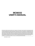
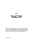
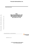
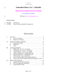
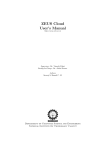
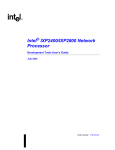
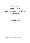
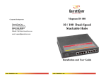
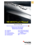
SECTION 7
TIME PROCESSOR UNIT
The time processor unit (TPU) is an intelligent, semi-autonomous microcontroller
designed for timing control. Operating simultaneously with the CPU32, the TPU
schedules tasks, processes microcode ROM instructions, accesses shared data with
the CPU32, and performs input and output functions. Figure 7-1 is a simplified block
diagram of the TPU.
HOST
INTERFACE
CONTROL
SCHEDULER
SERVICE REQUESTS
TIMER
CHANNELS
CHANNEL 0
CHANNEL
SYSTEM
CONFIGURATION
IMB3
DEVELOPMENT
SUPPORT AND
TEST
TCR1
T2CLK
PIN
CHANNEL 1
TCR2
PINS
MICROENGINE
CHANNEL
CONTROL
PARAMETER
RAM DATA
DATA
CONTROL
STORE
CONTROL AND DATA
EXECUTION
UNIT
CHANNEL 15
Figure 7-1 TPU Block Diagram
7.1 General
The TPU can be viewed as a special-purpose microcomputer that performs a programmable series of two operations, match and capture. Each occurrence of either
operation is called an event. A programmed series of events is called a function. TPU
functions replace software functions that would require CPU32 interrupt service. Two
sets of microcode ROM functions are currently available for most MCU derivatives with
the TPU.
The A mask set (or original mask set) includes the following functions:
• Discrete input/output
• Input capture/input transition counter
• Output compare
MC68332
USER’S MANUAL
TIME PROCESSOR UNIT
Rev. 15 Oct 2000
MOTOROLA
7-1
• Pulse width modulation
• Synchronized pulse width modulation
• Period measurement with additional transition detect
• Period measurement with missing transition detect
• Position-synchronized pulse generator
• Stepper motor
• Period/pulse width accumulator
• Quadrature decode
The G mask set (or motion control mask set) includes the following functions:
• Table stepper motor
• New input capture/transition counter
• Queued output match
• Programmable time accumulator
• Multichannel pulse width modulation
• Fast quadrature decode
• Universal asynchronous receiver/transmitter
• Brushless motor communication
• Frequency measurement
• Hall effect decode
7.2 TPU Components
The TPU consists of two 16-bit time bases, sixteen independent timer channels, a task
scheduler, a microengine, and a host interface. In addition, a dual-ported parameter
RAM is used to pass parameters between the module and the CPU32.
7.2.1 Time Bases
Two 16-bit counters provide reference time bases for all output compare and input
capture events. Prescalers for both time bases are controlled by the CPU32 via bit
fields in the TPU module configuration register (TPUMCR). Timer count registers
TCR1 and TCR2 provide access to the current counter values. TCR1 and TCR2 can
be read by TPU microcode, but are not directly available to the CPU32. The TCR1
clock is derived from the system clock. The TCR2 clock can be derived from the system clock or from an external clock input via the T2CLK pin.
7.2.2 Timer Channels
The TPU has 16 independent channels, each connected to an MCU pin. The channels
have identical hardware. Each channel consists of an event register and pin control
logic. The event register contains a 16-bit capture register, a 16-bit compare/match
register, and a 16-bit greater-than-or-equal-to comparator. The direction of each pin,
either output or input, is determined by the TPU microengine. Each channel can either
use the same time base for match and capture, or can use one time base for match
and the other for capture.
MC68332
USER’S MANUAL
TIME PROCESSOR UNIT
Rev. 15 Oct 2000
MOTOROLA
7-2
7.2.3 Scheduler
When a service request is received, the scheduler determines which TPU channel is
serviced by the microengine. A channel can request service for one of four reasons:
for host service, for a link to another channel, for a match event, or for a capture event.
The host system assigns each active channel one of three priorities: high, middle, or
low. When multiple service requests are received simultaneously, a priority-scheduling
mechanism grants service based on channel number and assigned priority.
7.2.4 Microengine
The microengine is composed of a control store and an execution unit. Control-store
ROM holds the microcode for each factory-masked time function. When assigned to a
channel by the scheduler, the execution unit executes microcode for a function
assigned to that channel by the CPU32. Microcode can also be executed from the
TPURAM module instead of the control store. The TPURAM allows emulation and
development of custom TPU microcode without the generation of a microcode ROM
mask. Refer to 7.3.6 Emulation Support for more information.
7.2.5 Host Interface
The host interface registers allow communication between the CPU32 and the TPU,
both before and during execution of a time function. The registers are accessible from
the IMB through the TPU bus interface unit. Refer to 7.6 Host Interface Registers
and APPENDIX D REGISTER SUMMARY for register bit/field definitions and address
mapping.
7.2.6 Parameter RAM
Parameter RAM occupies 256 bytes at the top of the system address map. Channel
parameters are organized as 128 16-bit words. Although all parameter word locations
in RAM can be accessed by all channels, only 100 are normally used: channels 0 to
13 use six parameter words, while channels 14 and 15 each use eight parameter
words. The parameter RAM address map in APPENDIX D REGISTER SUMMARY
shows how parameter words are organized in memory.
The CPU32 specifies function parameters by writing to the appropriate RAM address.
The TPU reads the RAM to determine channel operation. The TPU can also store
information to be read by the CPU32 in the parameter RAM. Detailed descriptions of
the parameters required by each time function are beyond the scope of this manual.
Refer to the TPU Reference Manual (TPURM/AD) and the Motorola TPU Literature
Package (TPULITPAK/D) for more information.
7.3 TPU Operation
All TPU functions are related to one of the two 16-bit time bases. Functions are synthesized by combining sequences of match events and capture events. Because the
primitives are implemented in hardware, the TPU can determine precisely when a
match or capture event occurs, and respond rapidly. An event register for each channel provides for simultaneity of match/capture event occurrences on all channels.
MC68332
USER’S MANUAL
TIME PROCESSOR UNIT
Rev. 15 Oct 2000
MOTOROLA
7-3
When a match or input capture event requiring service occurs, the affected channel
generates a service request to the scheduler. The scheduler determines the priority of
the request and assigns the channel to the microengine at the first available time. The
microengine performs the function defined by the content of the control store or emulation RAM, using parameters from the parameter RAM.
7.3.1 Event Timing
Match and capture events are handled by independent channel hardware. This provides an event accuracy of one time-base clock period, regardless of the number of
channels that are active. An event normally causes a channel to request service. The
time needed to respond to and service an event is determined by which channels and
the number of channels requesting service, the relative priorities of the channels
requesting service, and the microcode execution time of the active functions. Worstcase event service time (latency) determines TPU performance in a given application.
Latency can be closely estimated. For more information, refer to the TPU Reference
Manual (TPURM/AD)
7.3.2 Channel Orthogonality
Most timer systems are limited by the fixed number of functions assigned to each pin.
All TPU channels contain identical hardware and are functionally equivalent in operation, so that any channel can be configured to perform any time function. Any function
can operate on the calling channel, and, under program control, on another channel
determined by the program or by a parameter. The user controls the combination of
time functions.
7.3.3 Interchannel Communication
The autonomy of the TPU is enhanced by the ability of a channel to affect the operation of one or more other channels without CPU32 intervention. Interchannel
communication can be accomplished by issuing a link service request to another channel, by controlling another channel directly, or by accessing the parameter RAM of
another channel.
7.3.4 Programmable Channel Service Priority
The TPU provides a programmable service priority level to each channel. Three priority levels are available. When more than one channel of a given priority requests
service at the same time, arbitration is accomplished according to channel number. To
prevent a single high-priority channel from permanently blocking other functions, other
service requests of the same priority are performed in channel order after the lowestnumbered, highest-priority channel is serviced.
7.3.5 Coherency
For data to be coherent, all available portions of the data must be identical in age, or
must be logically related. As an example, consider a 32-bit counter value that is read
and written as two 16-bit words. The 32-bit value is read-coherent only if both 16-bit
portions are updated at the same time, and write-coherent only if both portions take
MC68332
USER’S MANUAL
TIME PROCESSOR UNIT
Rev. 15 Oct 2000
MOTOROLA
7-4
effect at the same time. Parameter RAM hardware supports coherent access of two
adjacent 16-bit parameters. The host CPU must use a long-word operation to guarantee coherency.
7.3.6 Emulation Support
Although factory-programmed time functions can perform a wide variety of control
tasks, they may not be ideal for all applications. The TPU provides emulation capability
that allows the user to develop new time functions. Emulation mode is entered by setting the EMU bit in TPUMCR. In emulation mode, an auxiliary bus connection is made
between TPURAM and the TPU, and access to TPURAM via the intermodule bus is
disabled. A 9-bit address bus, a 32-bit data bus, and control lines transfer information
between the modules. To ensure exact emulation, RAM module access timing
remains consistent with access timing of the TPU microcode ROM control store.
To support changing TPU application requirements, Motorola has established a TPU
function library. The function library is a collection of TPU functions written for easy
assembly in combination with each other or with custom functions. Refer to Motorola
Programming Note TPUPN00/D, Using the TPU Function Library and TPU Emulation Mode for information about developing custom functions and accessing the TPU
function library. Refer to the TPU Reference Manual (TPURM/AD) and the Motorola
TPU Literature Package (TPULITPAK/D) for more information about specific
functions.
7.3.7 TPU Interrupts
Each of the TPU channels can generate an interrupt service request. Interrupts for
each channel must be enabled by writing to the appropriate control bit in the channel
interrupt enable register (CIER). The channel interrupt status register (CISR) contains
one interrupt status flag per channel. Time functions set the flags. Setting a flag bit
causes the TPU to make an interrupt service request if the corresponding channel
interrupt enable bit is set and the interrupt request level is non-zero.
The value of the channel interrupt request level (CIRL) field in the TPU interrupt configuration register (TICR) determines the priority of all TPU interrupt service requests.
CIRL values correspond to MCU interrupt request signals IRQ[7:1]. IRQ7 is the highest-priority request signal; IRQ1 has the lowest priority. Assigning a value of %111 to
CIRL causes IRQ7 to be asserted when a TPU interrupt request is made; lower field
values cause corresponding lower-priority interrupt request signals to be asserted.
Assigning CIRL a value of %000 disables all interrupts.
The CPU32 recognizes only interrupt requests of a priority greater than the value contained in the interrupt priority (IP) mask in the status register. When the CPU32
acknowledges an interrupt request, the priority of the acknowledged interrupt is written
to the IP mask and is driven out onto the IMB address lines.
When the IP mask value driven out on the address lines is the same as the CIRL value,
the TPU contends for arbitration priority. The IARB field in TPUMCR contains the TPU
arbitration number. Each module that can make an interrupt service request must be
assigned a unique non-zero IARB value in order to implement an arbitration scheme.
MC68332
USER’S MANUAL
TIME PROCESSOR UNIT
Rev. 15 Oct 2000
MOTOROLA
7-5
Arbitration is performed by means of serial assertion of IARB field bit values. The IARB
of TPUMCR is initialized to $0 during reset.
When the TPU wins arbitration, it must respond to the CPU32 interrupt acknowledge
cycle by placing an interrupt vector number on the data bus. The vector number is
used to calculate displacement into the exception vector table. Vectors are formed by
concatenating the 4-bit value of the CIBV field in TICR with the 4-bit number of the
channel requesting interrupt service. Since the CIBV field has a reset value of $0, it
must be assigned a value corresponding to the upper nibble of a block of 16 userdefined vector numbers before TPU interrupts are enabled. Otherwise, a TPU interrupt
service request could cause the CPU32 to take one of the reserved vectors in the
exception vector table.
For more information about the exception vector table, refer to 4.9 Exception Processing. Refer to 5.8 Interrupts for further information about interrupts.
7.4 A Mask Set Time Functions
The following paragraphs describe factory-programmed time functions implemented in
the A mask set TPU microcode ROM. A complete description of the functions is
beyond the scope of this manual. Refer to the TPU Reference Manual (TPURM/AD)
for additional information.
7.4.1 Discrete Input/Output (DIO)
When a pin is used as a discrete input, a parameter indicates the current input level
and the previous 15 levels of a pin. Bit 15, the most significant bit of the parameter,
indicates the most recent state. Bit 14 indicates the next most recent state, and so on.
The programmer can choose one of the three following conditions to update the
parameter: 1) when a transition occurs, 2) when the CPU32 makes a request, or 3)
when a rate specified in another parameter is matched. When a pin is used as a discrete output, it is set high or low only upon request by the CPU32.
Refer to TPU programming note Discrete Input/Output (DIO) TPU Function
(TPUPN18/D) for more information.
7.4.2 Input Capture/Input Transition Counter (ITC)
Any channel of the TPU can capture the value of a specified TCR upon the occurrence
of each transition or specified number of transitions and then generate an interrupt
request to notify the CPU32. A channel can perform input captures continually, or a
channel can detect a single transition or specified number of transitions, then cease
channel activity until reinitialization. After each transition or specified number of transitions, the channel can generate a link to a sequential block of up to eight channels.
The user specifies a starting channel of the block and the number of channels within
the block. The generation of links depends on the mode of operation. In addition, after
each transition or specified number of transitions, one byte of the parameter RAM (at
an address specified by channel parameter) can be incremented and used as a flag to
notify another channel of a transition.
MC68332
USER’S MANUAL
TIME PROCESSOR UNIT
Rev. 15 Oct 2000
MOTOROLA
7-6
Refer to TPU programming note Input Capture/Input Transition Counter (ITC) TPU
Function (TPUPN16/D) for more information.
7.4.3 Output Compare (OC)
The output compare function generates a rising edge, a falling edge, or a toggle of the
previous edge in one of three ways:
1. Immediately upon CPU32 initiation, thereby generating a pulse with a length
equal to a programmable delay time.
2. At a programmable delay time from a user-specified time.
3. As a continuous square wave. Upon receiving a link from a channel, OC references, without CPU32 interaction, a specifiable period and calculates an offset:
OFFSET = PERIOD ⋅ RATIO
where “RATIO” is a parameter supplied by the user.
This algorithm generates a 50% duty-cycle continuous square wave with each high/
low time equal to the calculated offset. Due to offset calculation, there is an initial link
time before continuous pulse generation begins.
Refer to TPU programming note Output Compare (OC) TPU Function (TPUPN12/
D) for more information.
7.4.4 Pulse-Width Modulation (PWM)
The TPU can generate a pulse-width modulated waveform with any duty cycle from
zero to 100% (within the resolution and latency capability of the TPU). To define the
PWM, the CPU32 provides one parameter that indicates the period and another
parameter that indicates the high time. Updates to one or both of these parameters
can direct the waveform change to take effect immediately, or coherently beginning at
the next low-to-high transition of the pin.
Refer to TPU programming note Pulse-Width Modulation (PWM) TPU Function
(TPUPN17/D) for more information.
7.4.5 Synchronized Pulse-Width Modulation (SPWM)
The TPU generates a PWM waveform in which the CPU32 can change the period and/
or high time at any time. When synchronized to a time function on a second channel,
the synchronized PWM low-to-high transitions have a time relationship to transitions
on the second channel.
Refer to TPU programming note Synchronized Pulse-Width Modulation (SPWM)
TPU Function (TPUPN19/D) for more information.
7.4.6 Period Measurement with Additional Transition Detect (PMA)
This function and the following function are used primarily in toothed-wheel speedsensing applications, such as monitoring rotational speed of an engine. The period
MC68332
USER’S MANUAL
TIME PROCESSOR UNIT
Rev. 15 Oct 2000
MOTOROLA
7-7
measurement with additional transition detect function allows for a special-purpose
23-bit period measurement. It can detect the occurrence of an additional transition
(caused by an extra tooth on the sensed wheel) indicated by a period measurement
that is less than a programmable ratio of the previous period measurement.
Once detected, this condition can be counted and compared to a programmable number of additional transitions detected before TCR2 is reset to $FFFF. Alternatively, a
byte at an address specified by a channel parameter can be read and used as a flag.
A non-zero value of the flag indicates that TCR2 is to be reset to $FFFF once the next
additional transition is detected.
Refer to TPU programming note Period Measurement, Additional Transition
Detect (PMA) TPU Function (TPUPN15A/D) for more information.
7.4.7 Period Measurement with Missing Transition Detect (PMM)
Period measurement with missing transition detect allows a special-purpose 23-bit
period measurement. It detects the occurrence of a missing transition (caused by a
missing tooth on the sensed wheel), indicated by a period measurement that is greater
than a programmable ratio of the previous period measurement. Once detected, this
condition can be counted and compared to a programmable number of additional transitions detected before TCR2 is reset to $FFFF. In addition, one byte at an address
specified by a channel parameter can be read and used as a flag. A non-zero value of
the flag indicates that TCR2 is to be reset to $FFFF once the next missing transition is
detected.
Refer to TPU programming note Period Measurement, Missing Transition Detect
(PMM) TPU Function (TPUPN15B/D) for more information.
7.4.8 Position-Synchronized Pulse Generator (PSP)
Any channel of the TPU can generate an output transition or pulse, which is a projection in time based on a reference period previously calculated on another channel.
Both TCRs are used in this algorithm: TCR1 is internally clocked, and TCR2 is clocked
by a position indicator in the user's device. An example of a TCR2 clock source is a
sensor that detects special teeth on the flywheel of an automobile using PMA or PMM.
The teeth are placed at known degrees of engine rotation; hence, TCR2 is a coarse
representation of engine degrees. For example, each count represents some number
of degrees.
Up to 15 position-synchronized pulse generator function channels can operate with a
single input reference channel executing a PMA or PMM input function. The input
channel measures and stores the time period between the flywheel teeth and resets
TCR2 when the engine reaches a reference position. The output channel uses the
period calculated by the input channel to project output transitions at specific engine
degrees. Because the flywheel teeth might be 30 or more degrees apart, a fractional
multiplication operation resolves down to the desired degrees. Two modes of operation allow pulse length to be determined either by angular position or by time.
MC68332
USER’S MANUAL
TIME PROCESSOR UNIT
Rev. 15 Oct 2000
MOTOROLA
7-8
Refer to TPU programming note Position-Synchronized Pulse Generator (PSP)
TPU Function (TPUPN14/D) for more information.
7.4.9 Stepper Motor (SM)
The stepper motor control algorithm provides for linear acceleration and deceleration
control of a stepper motor with a programmable number of step rates of up to 14. Any
group of channels, up to eight, can be programmed to generate the control logic necessary to drive a stepper motor.
The time period between steps (P) is defined as:
P ( r ) = K1 – K2 ⋅ r
where r is the current step rate (1–14), and K1 and K2 are supplied as parameters.
After providing the desired step position in a 16-bit parameter, the CPU32 issues a
step request. Next, the TPU steps the motor to the desired position through an acceleration/deceleration profile defined by parameters. The parameter indicating the
desired position can be changed by the CPU32 while the TPU is stepping the motor.
This algorithm changes the control state every time a new step command is received.
A 16-bit parameter initialized by the CPU32 for each channel defines the output state
of the associated pin. The bit pattern written by the CPU32 defines the method of stepping, such as full stepping or half stepping. With each transition, the 16-bit parameter
rotates one bit. The period of each transition is defined by the programmed step rate.
Refer to TPU programming note Stepper Motor (SM) TPU Function (TPUPN13/D)
for more information.
7.4.10 Period/Pulse-Width Accumulator (PPWA)
The period/pulse-width accumulator algorithm accumulates a 16-bit or 24-bit sum of
either the period or the pulse width of an input signal over a programmable number of
periods or pulses (from one to 255). After an accumulation period, the algorithm can
generate a link to a sequential block of up to eight channels. The user specifies a starting channel of the block and number of channels within the block. Generation of links
depends on the mode of operation. Any channel can be used to measure an accumulated number of periods of an input signal. A maximum of 24 bits can be used for the
accumulation parameter. From one to 255 period measurements can be made and
summed with the previous measurement(s) before the TPU interrupts the CPU, allowing instantaneous or average frequency measurement, and the latest complete
accumulation (over the programmed number of periods).
The pulse width (high-time portion) of an input signal can be measured (up to 24 bits)
and added to a previous measurement over a programmable number of periods (one
to 255). This provides an instantaneous or average pulse-width measurement capability, allowing the latest complete accumulation (over the specified number of periods)
to always be available in a parameter. By using the output compare function in conjunction with PPWA, an output signal can be generated that is proportional to a
MC68332
USER’S MANUAL
TIME PROCESSOR UNIT
Rev. 15 Oct 2000
MOTOROLA
7-9
specified input signal. The ratio of the input and output frequency is programmable.
One or more output signals with different frequencies, yet proportional and synchronized to a single input signal, can be generated on separate channels.
Refer to TPU programming note Period/Pulse-Width Accumulator (PPWA) TPU
Function (TPUPN11/D) for more information.
7.4.11 Quadrature Decode (QDEC)
The quadrature decode function uses two channels to decode a pair of out-of-phase
signals in order to present the CPU32 with directional information and a position value.
It is particularly suitable for use with slotted encoders employed in motor control. The
function derives full resolution from the encoder signals and provides a 16-bit position
counter with rollover/under indication via an interrupt.
The counter in parameter RAM is updated when a valid transition is detected on either
one of the two inputs. The counter is incremented or decremented depending on the
lead/lag relationship of the two signals at the time of servicing the transition. The user
can read or write the counter at any time. The counter is free running, overflowing to
$0000 or underflowing to $FFFF depending on direction.
The QDEC function also provides a time stamp referenced to TCR1 for every valid signal edge and the ability for the host CPU to obtain the latest TCR1 value. This feature
allows position interpolation by the host CPU between counts at very slow count rates.
Refer to TPU programming note Quadrature Decode (QDEC) TPU Function
(TPUPN20/D) for more information.
7.5 G Mask Set Time Functions
The following paragraphs describe factory-programmed time functions implemented in
the motion control microcode ROM. A complete description of the functions is beyond
the scope of this manual.
Refer to the TPU Reference Manual (TPURM/AD) for additional information.
7.5.1 Table Stepper Motor (TSM)
The TSM function provides for acceleration and deceleration control of a stepper
motor with a programmable number of step rates up to 58. TSM uses a table in parameter RAM, rather than an algorithm, to define the stepper motor acceleration profile,
allowing the user to fully define the profile. In addition, a slew rate parameter allows
fine control of the terminal running speed of the motor independent of the acceleration
table. The CPU need only write a desired position, and the TPU accelerates, slews,
and decelerates the motor to the required position. Full and half step support is provided for two-phase motors. In addition, a slew rate parameter allows fine control of
the terminal running speed of the motor independent of the acceleration table.
Refer to TPU programming note Table Stepper Motor (TSM) TPU Function
(TPUPN04/D) for more information.
MC68332
USER’S MANUAL
TIME PROCESSOR UNIT
Rev. 15 Oct 2000
MOTOROLA
7-10
7.5.2 New Input Capture/Transition Counter (NITC)
Any channel of the TPU can capture the value of a specified TCR or any specified location in parameter RAM upon the occurrence of each transition or specified number of
transitions, and then generate an interrupt request to notify the CPU32. The times of
the most recent two transitions are maintained in parameter RAM. A channel can perform input captures continually, or a channel can detect a single transition or specified
number of transitions, ceasing channel activity until reinitialization. After each transition or specified number of transitions, the channel can generate a link to other
channels.
Refer to TPU programming note New Input Capture/Transition Counter (NITC) TPU
Function (TPUPN08/D) for more information.
7.5.3 Queued Output Match (QOM)
QOM can generate single or multiple output match events from a table of offsets in
parameter RAM. Loop modes allow complex pulse trains to be generated once, a
specified number of times, or continuously. The function can be triggered by a link from
another TPU channel. In addition, the reference time for the sequence of matches can
be obtained from another channel. QOM can generate pulse width modulated waveforms, including waveforms with high times of 0% or 100%. QOM also allows a TPU
channel to be used as a discrete output pin.
Refer to TPU programming note Queued Output Match (QOM) TPU Function
(TPUPN01/D) for more information.
7.5.4 Programmable Time Accumulator (PTA)
PTA accumulates a 32-bit sum of the total high time, low time, or period of an input
signal over a programmable number of periods or pulses. The accumulation can start
on a rising or falling edge. After the specified number of periods or pulses, PTA generates an interrupt request and optionally generates links to other channels.
From one to 255 period measurements can be made and summed with the previous
measurement(s) before the TPU interrupts the CPU32, providing instantaneous or
average frequency measurement capability, and the latest complete accumulation
(over the programmed number of periods).
Refer to TPU programming note Programmable Time Accumulator (PTA) TPU
Function (TPUPN06/D) for more information.
7.5.5 Multichannel Pulse-Width Modulation (MCPWM)
MCPWM generates pulse-width modulated outputs with full 0% to 100% duty cycle
range independent of other TPU activity. This capability requires two TPU channels
plus an external gate for one PWM channel. (A simple one-channel PWM capability is
supported by the QOM function).
MC68332
USER’S MANUAL
TIME PROCESSOR UNIT
Rev. 15 Oct 2000
MOTOROLA
7-11
Multiple PWMs generated by MCPWM have two types of high time alignment: edge
aligned and center aligned. Edge aligned mode uses n + 1 TPU channels for n PWMs;
center aligned mode uses 2n + 1 channels. Center aligned mode allows a user-defined
“dead time” to be specified so that two PWMs can be used to drive an H-bridge without
destructive current spikes. This feature is important for motor control applications.
Refer to TPU programming note Multichannel Pulse-Width Modulation (MCPWM)
TPU Function (TPUPN05/D) for more information.
7.5.6 Fast Quadrature Decode (FQD)
FQD is a position feedback function for motor control. It decodes the two signals from
a slotted encoder to provide the CPU32 with a 16-bit free running position counter.
FQD incorporates a “speed switch” which disables one of the channels at high speed,
allowing faster signals to be decoded. A time stamp is provided on every counter
update to allow position interpolation and better velocity determination at low speed or
when low resolution encoders are used. The third index channel provided by some
encoders is handled by the NITC function.
Refer to TPU programming note Fast Quadrature Decode (FQD) TPU Function
(TPUPN02/D) for more information.
7.5.7 Universal Asynchronous Receiver/Transmitter (UART)
The UART function uses one or two TPU channels to provide asynchronous serial
communication. Data word length is programmable from one to 14 bits. The function
supports detection or generation of even, odd, and no parity. Baud rate is freely programmable and can be higher than 100 Kbaud. Eight bidirectional UART channels
running in excess of 9600 baud can be implemented.
Refer to TPU programming note Universal Asynchronous Receiver/Transmitter
(UART) TPU Function (TPUPN07/D) for more information.
7.5.8 Brushless Motor Commutation (COMM)
This function generates the phase commutation signals for a variety of brushless
motors, including three-phase brushless DC motors. It derives the commutation state
directly from the position decoded in FQD, thus eliminating the need for hall effect
sensors.
The state sequence is implemented as a user-configurable state machine, thus
providing a flexible approach with other general applications. An offset parameter is
provided to allow all the switching angles to be advanced or retarded on the fly by the
CPU32. This feature is useful for torque maintenance at high speeds.
Refer to TPU programming note Brushless Motor Commutation (COMM) TPU
Function (TPUPN09/D) for more information.
MC68332
USER’S MANUAL
TIME PROCESSOR UNIT
Rev. 15 Oct 2000
MOTOROLA
7-12
7.5.9 Frequency Measurement (FQM)
FQM counts the number of input pulses to a TPU channel during a user-defined window period. The function has single shot and continuous modes. No pulses are lost
between sample windows in continuous mode. The user selects whether to detect
pulses on the rising or falling edge. This function is intended for high speed measurement; measurement of slow pulses with noise rejection can be made with PTA.
Refer to TPU programming note Frequency Measurement (FQM) TPU Function
(TPUPN03/D) for more information.
7.5.10 Hall Effect Decode (HALLD)
This function decodes the sensor signals from a brushless motor, along with a direction input from the CPU32, into a state number. The function supports two- or threesensor decoding. The decoded state number is written into a COMM channel, which
outputs the required commutation drive signals. In addition to brushless motor applications, the function can have more general applications, such as decoding option
switches.
Refer to TPU programming note Hall Effect Decode (HALLD) TPU Function
(TPUPN10/D) for more information.
7.6 Host Interface Registers
The TPU memory map contains three groups of registers:
• System configuration registers
• Channel control and status registers
• Development support and test verification registers
All registers except the channel interrupt status register (CISR) must be read or written
by means of word accesses. The address space of the TPU memory map occupies
512 bytes. Unused registers within the 512-byte address space return zeros when
read.
7.6.1 System Configuration Registers
The TPU configuration control registers, TPUMCR and TICR, determine the value of
the prescaler, perform emulation control, specify whether the external TCR2 pin functions as a clock source or as gate of the DIV8 clock for TCR2, and determine interrupt
request level and interrupt vector number assignment. Refer to APPENDIX D REGISTER SUMMARY for more information about TPUMCR and TICR.
7.6.1.1 Prescaler Control for TCR1
Timer count register one (TCR1) is clocked from the output of a prescaler. Two fields
in TPUMCR control TCR1. The prescaler's input is the internal TPU system clock
divided by either 4 or 32, depending on the value of the PSCK bit. The prescaler
divides this input by 1, 2, 4, or 8, depending on the value of TCR1P. Channels using
TCR1 have the capability to resolve down to the TPU system clock divided by 4. Refer
to Figure 7-2 and Table 7-1.
MC68332
USER’S MANUAL
TIME PROCESSOR UNIT
Rev. 15 Oct 2000
MOTOROLA
7-13
DIV4 CLOCK
÷4
SYSTEM
CLOCK
0
15
00 ÷ 1
01 ÷ 2
10 ÷ 4
11 ÷ 8
1 – DIV4
0 – DIV32
DIV32 CLOCK
÷ 32
TCR1
PRESCALER
PSCK
MUX
TCR1
TPU PRE BLOCK 1
Figure 7-2 TCR1 Prescaler Control
Table 7-1 TCR1 Prescaler Control
PSCK = 0
PSCK = 1
TCR1
Prescaler
Divide
By
Number of
Clocks
Rate at
20.97 MHz
Number of
Clocks
Rate at
20.97 MHz
00
1
32
1.6 µs
4
200 ns
01
2
64
3.2 µs
8
400 ns
10
4
128
6.4 µs
16
0.8 µs
11
8
256
12.8 µs
32
1.6 µs
7.6.1.2 Prescaler Control for TCR2
Timer count register two (TCR2), like TCR1, is clocked from the output of a prescaler.
The T2CG bit in TPUMCR determines whether the T2CLK pin functions as an external
clock source for TCR2 or as the gate in the use of TCR2 as a gated pulse accumulator.
The function of the T2CG bit is shown in Figure 7-3.
TCR2
PRESCALER
T2CLK
PIN
SYNCHRONIZER
DIGITAL
FILTER
MUX
CONTROL
A
B
00 ÷
01 ÷
10 ÷
11 ÷
1
2
4
8
15
0
TCR2
DIV8 CLK
0–A
1–B
T2CG CONTROL BIT
TPU PRE BLOCK 2
Figure 7-3 TCR2 Prescaler Control
MC68332
USER’S MANUAL
TIME PROCESSOR UNIT
Rev. 15 Oct 2000
MOTOROLA
7-14
When T2CG is set, the external TCR2 pin functions as a gate of the DIV8 clock (the
TPU system clock divided by eight). In this case, when the external TCR2 pin is low,
the DIV8 clock is blocked, preventing it from incrementing TCR2. When the external
TCR2 pin is high, TCR2 is incremented at the frequency of the DIV8 clock. When
T2CG is cleared, an external clock from the TCR2 pin, which has been synchronized
and fed through a digital filter, increments TCR2.
The TCR2 field in TPUMCR specifies the value of the prescaler: 1, 2, 4, or 8. Channels
using TCR2 have the capability to resolve down to the TPU system clock divided by
eight. Table 7-2 is a summary of prescaler output.
Table 7-2 TCR2 Prescaler Control
TCR2 Prescaler
Divide By
Internal Clock
Divided By
External Clock
Divided By
00
1
8
1
01
2
16
2
10
4
32
4
11
8
64
8
7.6.1.3 Emulation Control
Asserting the EMU bit in TPUMCR places the TPU in emulation mode. In emulation
mode, the TPU executes microinstructions from TPURAM exclusively. Access to the
TPURAM module through the IMB is blocked, and the TPURAM module is dedicated
for use by the TPU. After reset, EMU can be written only once.
7.6.1.4 Low-Power Stop Control
If the STOP bit in TPUMCR is set, the TPU shuts down its internal clocks, shutting
down the internal microengine. TCR1 and TCR2 cease to increment and retain the last
value before the stop condition was entered. The TPU asserts the stop flag (STF) in
TPUMCR to indicate that it has stopped.
7.6.2 Channel Control Registers
The channel control and status registers enable the TPU to control channel interrupts,
assign time functions to be executed on a specified channel, or select the mode of
operation or the type of host service request for the time function specified. Refer to
Table 7-4.
7.6.2.1 Channel Interrupt Enable and Status Registers
The channel interrupt enable register (CIER) allows the CPU32 to enable or disable
the ability of individual TPU channels to request interrupt service. Setting the appropriate bit in the register enables a channel to make an interrupt service request; clearing
a bit disables the interrupt.
MC68332
USER’S MANUAL
TIME PROCESSOR UNIT
Rev. 15 Oct 2000
MOTOROLA
7-15
The channel interrupt status register (CISR) contains one interrupt status flag per
channel. Time functions specify via microcode when an interrupt flag is set. Setting a
flag causes the TPU to make an interrupt service request if the corresponding CIER
bit is set and the CIRL field has a non-zero value. To clear a status flag, read CISR,
then write a zero to the appropriate bit. CISR is the only TPU register that can be
accessed on a byte basis.
7.6.2.2 Channel Function Select Registers
Encoded 4-bit fields within the channel function select registers specify one of 16 time
functions to be executed on the corresponding channel. Encodings for predefined
functions in the TPU ROM are found in Table 7-3.
Table 7-3 TPU Function Encodings
A Mask Set
Function Name
G Mask Set
Function Code
Function Name
Function Code
PPWA
Period/pulse width
accumulator
$F
PTA
Programmable time accumulator
$F
OC
Output compare
$E
QOM
Queued output match
$E
SM
Stepper motor
$D
TSM
Table stepper motor
$D
PSP
Position-synchronized
pulse generator
$C
FQM
Frequency
measurement
$C
PMA/PMM
Period measurement
with additional/missing
transition detect
$B
UART
Universal
asynchronous
receiver/transmitter
$B
ITC
Input capture/input transition counter
$A
NITC
New input transition
counter
$A
PWM
Pulse width modulation
$9
COMM
Multiphase motor
commutation
$9
DIO
Discrete input/output
$8
HALLD
Hall effect decode
$8
SPWM
Synchronized pulse
width modulation
$7
—
—
QDEC
Quadrature decode
$6
—
—
MC68332
USER’S MANUAL
TIME PROCESSOR UNIT
Rev. 15 Oct 2000
MOTOROLA
7-16
7.6.2.3 Host Sequence Registers
The host sequence field selects the mode of operation for the time function selected
on a given channel. The meaning of the host sequence bits depends on the time function specified. Refer to Table 7-4, which is a summary of the host sequence and host
service request bits for each time function. Refer to the TPU Reference Manual
(TPURM/AD) and the Motorola TPU Literature Package (TPULITPAK/D) for more
information.
7.6.2.4 Host Service Registers
The host service request field selects the type of host service request for the time function selected on a given channel. The meaning of the host service request bits is
determined by time function microcode. Refer to the TPU Reference Manual
(TPURM/AD) and the Motorola TPU Literature Package (TPULITPAK/D) for more
information.
A host service request field of %00 signals the CPU that service is completed and that
there are no further pending host service requests. The host can request service on a
channel by writing the corresponding host service request field to one of three nonzero states. It is imperative for the CPU to monitor the host service request register
and wait until the TPU clears the service request for a channel before changing any
parameters or issuing a new service request to the channel.
7.6.2.5 Channel Priority Registers
The channel priority registers (CPR1, CPR2) assign one of three priority levels to a
channel or disable the channel. Table 7-4 indicates the number of time slots guaranteed for each channel priority encoding.
Table 7-4 Channel Priority Encodings
CHX[1:0]
Service
Guaranteed Time Slots
00
Disabled
—
01
Low
1 out of 7
10
Middle
2 out of 7
11
High
4 out of 7
7.6.3 Development Support and Test Registers
These registers are used for custom microcode development or for factory test.
Describing the use of these registers is beyond the scope of this manual. Register
descriptions are provided in APPENDIX D REGISTER SUMMARY. Refer to the TPU
Reference Manual (TPURM/AD) for more information.
MC68332
USER’S MANUAL
TIME PROCESSOR UNIT
Rev. 15 Oct 2000
MOTOROLA
7-17
MC68332
USER’S MANUAL
TIME PROCESSOR UNIT
Rev. 15 Oct 2000
MOTOROLA
7-18