1
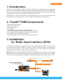
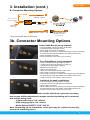
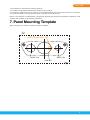
GET CONNECTED Installation & Operation Manual DEVICE INTEGRATION AND CHARGING KIT TranzIt USB IS32 Note to Readers, The information contained within the following documentation is subject to change without notice. Features discussed therein may be revised and/or updated to reflect mobile device compatibility fixes, as well as firmware revisions. To ensure that you have the most recent version of the product documentation, please download the PDF file from the product support section of www.iSimpleSolutions.com, or consult the User Manual section of the TranzIt USB application installed on a compatible mobile device. Rev. 071311 Table of Contents Pages 1. Introduction 1 2. TranzIt™USB Components 1 3. Installation 1 3a. Radio Input Interface (IS32) 1 3b. Connector Mounting Options 3 - Under Dash - Face Plate Mount - Individual 5. Troubleshooting 4 6. W arranty Information 4 7. P anel Mounting Template 5 TranzIt USB 1. Introduction Thank you for choosing the iSimple TranzIt™ USB as your portable audio car integration solution. The TranzIt USB is designed to provide a connecting link between your portable audio device and your car stereo. Using the hardware included in this kit, you can connect virtually any audio source directly to any factory or aftermarket car radio. Additionally, The TransIt USB provides a USB charging port, so you can use the USB cable included with your portable device to keep its battery fully charged and ready to go. 2. TranzIt™USB Components • One radio input interface • One under dash mount • One panel mount • Four screws • One 3.5 mm-to-3.5 mm audio cable (48” long) • One USB charging port with connecting cable (48” long) • One 3.5mm audio input with connecting cable (68” long) • One cable with on/off switch (31” long) • One manual with a “Panel Mounting Template” (page 5) 3. Installation 3a. Radio Input Interface (IS32) The radio input interface is designed to install inline with the radio antenna usually located on the back of the radio headunit. However, in some cases this radio connection may be at a remote location in the vehicle. Please consult the vehicle manufacturer’s information or owner’s manual for more information. NOTE: With some vehicle makes and models, the installation of the Radio Input Interface will require the use of an antenna adapter (sold separately). These adapters are available from most car audio installation retailers or the iSimple website (www.isimplesolutions.com). Specific USB Cab for Your Device Ground Connection Connec t to a c lea n ground point (Not included) Connects to Power Sour ce ACC 12VDC P o wer wh en key-o n Radio Tuning Frequency USB Power Cable 2A Fuse Use to select best operating frequency for your area 2.5mm Audio On/Off Switch IS32 3.5 mm Audio Input 3.5mm Audio input Antenna Input from vehicle antenna* Antenna Out to FM radio* Radio 1 TranzIt USB BE AWARE: Before installing the Radio Input Interface make sure you disconnect the battery. Then make the following connections on the radio input interface, take into consideration the connector cable’s length and desired mounting locations for the connectors. Be sure the cables will reach to make any proper adjustment. 1) Using a multimeter, identify 12v+ and ground wires behind the radio. a) Connect the Radio Input Interface module’s red wire to 12v+ (ignition) b) Connect the Radio Input Interface module’s black wire to ground c) Connect the vehicle’s antenna into the Radio Input Interface module’s antenna input* d) Connect the Radio Input Interface module’s antenna output into the radio* *A vehicle specific antenna adaptor may be required to make these connections. 2) The power switch supplied will turn the device on and off by connecting the 2.5mm cable. When the switch is in the on position, the Radio Input Interface module will interrupt the incoming antenna signal, delivering a strong, clean signal from your device directly to your FM radio. To regain standard FM reception, turn the switch to the off position. 3) While the FM Transmitter is on, Please select the FM frequency through which you will access your new audio device. There is a label on the side of the module that says “Tuning Frequency”. By this label is a two position switch. Use this switch to select the best possible frequency for operation. Note the position of the switch before continuing with installation of the interface. If you have a local radio station that occupies either of these frequencies (87.9 or 88.3) please move the switch to the position that does NOT match the local station. This preset Specific USB Cable Ground Connection Ground Connection for Your Device will act as the “radio station” your audio will play through. Connec t to adevice c lea n ground point (Not included) Connec t to a c lea n ground point Connects to Power Sour ce ACC 12VDC Connects to Power Sour ce ACC 12VDC USB Power Cable P o wer wh en key-o n Radio Tuning Frequency 2A FuseUse to select best operating 2.5mm frequency for your area P o wer wh en key-o n Radio Tuning Frequency Use to select best operating frequency for your area USB Pow 2A Fuse Audio On IS32 On/Off Switch Audio Antenna Input 3.5 mm Audio Input IS32 from vehicle antenna* 3.5 mm Audio Input 3.5mm Audio input Input Antenna Antenna Out from vehicle antenna* music player 3.5mm Audio input to FM radio* Radio Antenna Out to FM radio* 3) Once the Radio Input Interface module is installed correctly, connect the 3.5mm Audio Radio Input to your device to set the audio level propertly by using the gain adjustment (see Input BACK VIEW image). When set correctly, the audioAntenna levelInput of the Radio Input Interface moduleAudio will match from vehicle antenna* Left & Right the volume of a typical FM radio station. L + H 3.5mm Antenna Out LEVEL Audio input to FM radio* Gain Adjustment BACK VIEW Input ntenna* LEVEL L Out +H Audio Input Use to match volume of IS32 to volume of FM radio stations Left & Right 3.5mm Audio input Gain Adjustment Use to match volume of IS32 to volume of FM radio stations 4) USB Charging capability is always ON while the vehicle is in RUN Position. 2 2.5mm music player TranzIt USB 2.5mm Connector 3. Installation (cont.) Audio ON/OFF Switch B. Connector Mounting Options 2.5mm Connector Antenna Input from vehicle antenna* Antenna Input from vehicle antenna* m Connector Audio ON/OFF Switch 3/8” 3.5mm Audio Input Antenna Out “Factory Look” 3.5 mm Dash Panel Mount Audio input (6 ft.) to FM radio* 3.5mm Audio Input Audio Antenna Out to FM radio* ON/OFF 3.5 mm to 3.5 mm Audio Cable (4 ft.) Switch USB Power Cable USB Power Cable Specific USB Cable for Your Device 3.5mm (Not included) Audio Input * Some Antenna Adapter May the Be Required * radios require addition antenna connection adapters * Some radios require the addition of antenna connectionof adapters 3b. Connector MOUNTING OPTIONS MOUNTING OPTIONS USB Power Cable n of antenna connection adapters UNDER-DASH MOUNT (use of bracket) •Easy installation •Strong Support Mounting Options UnderUSB Dash Mount (using bracket) Specific Cable music player • Choose under dash for Yoursuitable Devicemounting position •Easy to secure individually. •No unnecessary drilling music player (Not included) PANEL MOUNT (use of faceplate) •Stylish finish •No unnecessary drilling (Not included) • Install the bracket using two screws (Not included) • Mount audio connectors to faceplate • Mount USB connector by carefully removing the fuse and passing the fuseholder through the middle of the USB mounting hole PANEL MOUNT •(use of faceplate) Attach faceplate to bracket CUSTOM MOUNT (separate cables) order, Any place •Stylish finish • Install connectors to the Radio•Any Input Interface UNDER-DASH MOUNT (use of bracket) •Easy installation •Strong Support Specific USB Cable for Your Device Specific USB Cab for Your Device music player PANEL MOUNT (use of faceplate) Face Plate Mount •Stylish finish(using faceplate) • Choose suitable mounting position on dash •No unnecessary drilling • Confirm the proper hole position by using the “Panel Mounting Template” (page 5) • Mark the mounting holes • Drill the mounting holes • Attach the mounting panel with small screws • Mount audio connectors to faceplate • Mount USB connector by carefully removing the fuse and passing CUSTOM MOUNT (separate cables) the fuseholder through the middle of the USB mounting hole •Any order, Any placeInput Interface • Install connectors to the Radio •Easy to secure individually. Individual (in-dash installation)* • Choose suitable mounting position on dash • Carefully measure and drill holes for installation • Mount audio connectors • Mount USB connector by carefully removing the fuse and passing the fuseholder through the middle of the USB mounting hole • Install connectors to the Radio Input Interface *CUSTOM If youMOUNT choose to mount (separate cables)the cables via the individual connector mounting •Any order, Any place holes some drilling adjustments maybe needed depending on the material •Easy to secure and drill bit individually. being used. - 3.5mm audio input: 3/8” drill bit - USB charging input: 3/4” drill bit - Audio Switch ON/OFF: 9/16” drill bit Note: Depending up on installation, some glue may be required to properly secure the mounting pieces. 3 CUSTOM •Any or •Easy to TranzIt USB 5. Troubleshooting Symptom Cause Remedy No Audio from the Aux source 1) TranzIt™USB is turned off Press Power Button 2) Connection cables are disconnected Check all interconnects for proper connection 3) The radio is not on the correct station Verify that the FM radio is tuned to the frequency on the side of the interface. 1) The power connection on the TranzIt™USB is disconnected Connect power cable according to Configuration 1 in Section 3 2) The fuse may be blown in the power plug on the docking cable If fuse is blown, replace with equivalent fuse 1) Improper selection of TranzIt™USB frequency Tune to the frequency specified on the side of the TranzIt™USB interface. 2) Local radio station is interfering with the auxiliary input device Change the frequency setting on the side of the TranzIt™USB to the other position, and use the new frequency to access the audio source 1) The volume is down on the audio source Turn up the volume on the source to ensure best sound quality through the TranzIt™USB The TranzIt™USB gain is set too low Adjust the gain setting on the back side of the TranzIt™USB iPod/iPhone does not charge Noise / Static Low audio 6. Warranty Information One Year Limited Warranty The quality controls used in the manufacture of this product will ensure your satisfaction. This warranty applies only to the original purchaser of this product from an authorized iSimple® dealer. This warranty covers any supplied or manufactured parts of this product that, upon inspection by iSimple® authorized personnel, is found to have failed in normal use due to defects in material or workmanship. This warranty does not apply to installation expenses. Attempting to service or modify this unit, operating this unit under conditions other than the recommended voltage will render this WARRANTY VOID. Unless otherwise prescribed by law, iSimple® shall not be liable for any personal injury, property damage and or any incidental or consequential damages of any kind (including water damage) resulting from malfunctions, defects, misuse, improper installation or alteration of this product. All parts of this iSimple® product are guaranteed for a period of 1 year as follows: Within the first 12 months from date of purchase, subject to the conditions above, iSimple® will repair or replace the product at our discretion, if it is defective in material or workmanship providing it is returned to an Authorized iSimple®’ dealer, with PROOF OF PURCHASE from an authorized iSimple® dealer. Warning: This equipment may be reset by unintentional electrostatic discharge Exposure to direct sunlight or extreme heat may cause damage or malfunction. during operation. FCC Class B Radio Frequency Interference Statement This equipment has been tested and found to comply with the limits for a Class B digital device, pursuant to Part 15 of FCC rules. These limits are designed to provide reasonable protection against harmful interference in a residential installation. This equipment generates, uses, and can radiate radio frequency energy and, if not installed and used in accordance with the instructions, may cause harmful interference to radio communications. However, there is no guarantee that interference will not occur in a particular installation. If this equipment does cause harmful interference to radio or television reception, which can be determined by turning the equipment off and on, the user is encouraged to try to correct the interference by one or more of the following measures: 4 TranzIt USB 1. Re-orientate or relocate the receiving antenna. 2. Increase the separation between the equipment and receiver. 3. Connect the equipment into an outlet on a circuit different from that of which the receiver is connected. 4. Consult the dealer or an experienced radio / television technical for help. Notice : The changes or modifications not expressly approved by the party responsible compliance could void the user authority to operate the equipment. 7. Panel Mounting Template We recomend you to make a copies for proper installation USB Alignment Tab 0.565” dia. 0.358” dia. 0.86” dia. 5 For Best Performance Have It Professionally Installed A division of AAMP of America™ 13190 56th Court Clearwater, Florida 33760 Ph. 866-788-4237 [email protected] ©2013 AAMP of Florida, Inc. www.iSimpleSolutions.com