1
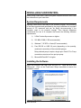
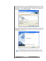
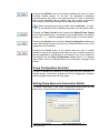
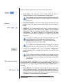
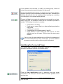
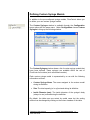
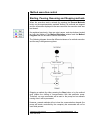
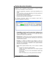
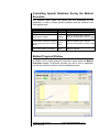
FlowControl User’s Manual
Catalog No: 70-6000
phone: 508.893.8999
e-mail: [email protected]
web: www.harvardapparatus.com
FlowControl User Manual
5421-002 Rev B
© 2011 Harvard Apparatus
1
TABLE OF CONTENTS
INSTALLING FLOW CONTROL .......................................................... 4
System Requirements................................................................ 4
Installing the Software ............................................................... 4
PUMP NETWORKS AND MODELS ..................................................... 6
Compatible Network Topologies................................................... 6
Compatible Pump Models............................................................. 6
Pump Communications Protocols................................................. 7
FLOW CHART OUTLINING HOW TO RUN FLOWCONTROL ............ 8
DEFINING PUMPS ............................................................................... 8
Pump Configuration Assistant .................................................... 11
Setting Pump Name and Connection Details.............................. 11
Identifying the Connected Pump ................................................ 13
Selecting the Mounted Rack Model and Number of Syringes..... 14
Removing Pumps From the System ........................................... 15
Manual Pump Control................................................................. 15
Defining Custom Syringe Models ............................................... 17
Adding and Editing Custom Syringe Models............................... 18
Removing Custom Syringe Models ............................................ 18
DEFINING METHODS ........................................................................ 19
Removing Methods..................................................................... 20
Method Editor Tool ..................................................................... 20
Method Name, Description and Dates........................................ 21
Pump and Rack Model Selection ............................................... 21
Number of Syringes, Syringe Model and Flow Units Selection ... 22
Flow Evolution Graph: Steps and Flow Definition....................... 23
Visualizing Steps: Step Blocks ................................................... 24
Graph’s Axis………………….. .................................................... 25
Status Bar Information................................................................ 27
Spreadsheet View…................................................................... 27
Adding New Sequential Steps to the Method ............................. 28
Changing the Properties of a Step.............................................. 30
Inserting Steps Into a Method..................................................... 31
Removing Steps From the Method ............................................. 32
Defining a Loop Within a Method ............................................... 32
Protecting the Pump Against Forced Flow Rates ....................... 33
Steps Approaching Zero and Steps Changing Flow Direction .... 33
Expected Flow vs. Real Flow ..................................................... 33
Concentration Wizard................................................................. 34
Accepting and Cancelling a Method Edit .................................... 37
Copying a Method. ..................................................................... 37
Importing and Exporting Methods ............................................... 37
EXECUTING METHODS .................................................................... 40
Assigning Methods to a Pump.................................................... 41
Method Execution Control .......................................................... 42
FlowControl User Manual
5421-002 Rev B
© 2011 Harvard Apparatus
2
Starting, Pausing, Resuming and Stopping Methods ................. 42
Runtime Execution Information .................................................. 43
Controlling Special Situations During the Method Execution ...... 44
Method Progress window ........................................................... 44
Method Data Logging ................................................................. 46
Excel Report............................................................................... 46
Bitmap Report ............................................................................ 48
Experimental Notes .................................................................... 48
Leaving the Execution Task ....................................................... 48
APPENDICES..................................................................................... 49
Connectivity Cables.................................................................... 49
FlowControl User Manual
5421-002 Rev B
© 2011 Harvard Apparatus
3
INSTALLING FLOWCONTROL
Before using FlowControl, check the system requirements and then install
the software onto your hard drive.
System Requirements
Although FlowControl is an easy-to-use software program, the processing
of the data requested and generated by the pumps mobilizes an important
amount of PC resources and can be highly time-consuming if the
computer used is not powerful enough. Thus Harvard Apparatus
recommends the use of a computer that meets the following minimum
requirements:
1)
2 GHz Pentium® processor or higher.
2)
512 MB of RAM (1 GB recommended)
3)
Windows 7, XP SP3 or Vista (XP recommended)
4)
Free RS-232 or USB 2.0 ports (depending on the quantity,
model and connectivity of the controlled pumps).
Daisy-chained pumps require a single port. Direct PC to Pump
connections require one free port per pump.
5)
Microsoft® Excel® 97 or higher.
Installing the Software
Insert the provided USB Flash Drive into your PC. Open the drive titled
‘PBLicense’. Click on the FlowControl Setup executable to launch the
installation wizard.
FlowControl User Manual
5421-002 Rev B
© 2011 Harvard Apparatus
4
Press the Next button to move to the Destination Location screen. Select
the location that you would like FlowControl to be saved on your PC then
press Next. In the specified location, FlowControl will download an
executable file and a reference database.
Once successfully installed, you will have the option to run FlowControl
immediately. To do so, click the dialog box ‘Run FlowControl Now’ and
then press the Finish button.
The USB Flash Drive contains the FlowControl software license
and must be plugged into the PC whenever FlowControl is in use.
FlowControl User Manual
5421-002 Rev B
© 2011 Harvard Apparatus
5
PUMP NETWORKS AND MODELS
FlowControl is able to communicate with a pump connected to a computer
by means of a serial / USB communications protocol.
Compatible Network Topologies
The following pump network topologies can be controlled by FlowControl:
•
Direct Connection: Each pump is connected to a single serial / USB
port.
•
Daisy-chain: A single pump is connected directly to the computer
and the rest of the pumps are sequentially “chained” to the previous
one. In order to uniquely identify the pumps available within the
chain, each of them must be assigned an address number (from 0 to
99).
The limitation of how many pumps can be connected in a daisy chain,
depends on the pump model.
•
•
•
PHD 22/2000 chains = 20 pumps
Pump 11 Elite chains = 20 pumps
PHD ULTRA chains = 50 pumps
This restriction will be applied in the pump configuration tool by not
allowing you to configure daisy chains that do not comply with the
above restrictions.
When communicating with a PHD ULTRA or Elite pump via USB the
pump’s drivers must be installed on your PC. These drivers can be
found on the CD that was shipped with the ULTRA or Elite pump.
Compatible Pump Models
The following pump models are compatible with FlowControl:
•
•
•
PHD 22/2000 (44 Protocol)
11 Elite (Elite Protocol)
PHD ULTRA (ULTRA Protocol)
OEM modules may be also controlled by the application if they
comply with any the ULTRA communication protocols.
Max / Min flow rates in FlowControl may not match up
exactly to the pump’s protocol.
FlowControl User Manual
5421-002 Rev B
© 2011 Harvard Apparatus
6
FlowControl is compatible with the following pump software
versions and any newer revisions:
PHD 22/2000
v1p12a
11 Elite
v1.0.4
PHD ULTRA
v1.3.3
Pump Communications Protocols
FlowControl is responsible for selecting and fulfilling the communications
protocol suitable for each pump with which it will communicate.
The communications protocol of each model that the application will utilize
is described in the pump’s corresponding user manual.
FlowControl uses the following command latency for each pump:
PHD 22/2000
500 ms
11 Elite
250 ms
PHD ULTRA
250 ms
FlowControl is thus responsible for sending the corresponding commands
to each pump (from their particular commands set) in order to control
them.
Within a daisy-chain network topology, all the pumps must be
configured, by the user, to have the same communication
parameters (baud rate)
USB-based pumps are controlled by FlowControl through a “virtual”
serial port automatically created by the pump’s driver. Thus, all
pumps are considered to be connected to the PC by means of a
serial port (virtual or physical).
FlowControl User Manual
5421-002 Rev B
© 2011 Harvard Apparatus
7
Flow chart outlining how to run FlowControl
DEFINING PUMPS
Open the FlowControl software by double-clicking on the corresponding
icon in the Windows® desktop. An initial blank screen will be opened.
FlowControl User Manual
5421-002 Rev B
© 2011 Harvard Apparatus
8
Before using the rest of the application functionalities, FlowControl must
establish communication with any pumps that will be controlled by the
software.
To open the Pump Configuration window click on the ‘Configure Pumps’
button located at the top of the screen.
When the Pump Configuration window is first launched FlowControl will
automatically check for connected pumps. If a pump is detected the
Pump Configuration Assistant will launch. (see page 11)
The rest of the menu options (Define Methods and Execute
Methods), will be disabled while the Pump Configuration window is
active.
The Pump Configuration window shows the list of defined pumps to be
considered within the rest of the application’s options (such as Method
creation and execution).
Each defined pump is represented by a row in a table with the following
information:
• Status: shows an icon representing the connectivity of the pump :
o Green: Ready. The pump is correctly defined and connected
to the computer.
o Gray: Off-line. The pump was correctly defined but it is not
currently connected to the computer.
o Red: Wrong. The pump model currently connected to the
computer does not match with the defined pump.
FlowControl User Manual
5421-002 Rev B
© 2011 Harvard Apparatus
9
Note that if you close and restart FlowControl, pumps
connected via a USB cable may re-establish communication
through a different COM port than was previously defined.
Therefore, if multiple pumps are defined they could potentially
change COM ports during a re-start. Be sure to verify which
pump you are communicating with before running a method.
Except for “green” status, the row color (text foreground color) coincides
with the status icon color in order to facilitate its visual identification.
•
Pump Name: shows the name assigned to the pump during its
definition.
•
Pump Model: shows the name of the pump model detected by the
software.
•
Serial Number: shows the serial number of the pump entered during
its definition.
•
Communication: shows the communications port name (COM port)
and the address of the pump entered during its definition in the
following format :
<COM port name> [<Pump address>]
By default, table rows are sorted by connection, that is, by COM port and
address. Sorting can be changed by clicking on the column headers of the
table.
The Pump Configuration window includes a toolbar with the following
buttons:
•
Add New: Launches the Pump Configuration assistant tool in
order to define a new pump. This button is enabled only if the total
quantity of defined pumps has not reached the limit.
•
Edit: Launches the Pump Configuration assistant tool in order to
modify a previously defined pump. This button is enabled when one
(and only one) pump is selected.
•
Delete: Asks the user to confirm whether to remove the selected
pump(s). This button is enabled when at least one pump is selected.
See “Removing Pumps from the System” on page 10 for more
details.
FlowControl User Manual
5421-002 Rev B
© 2011 Harvard Apparatus
10
Pressing the Refresh button of the window updates the status of all the
currently defined pumps. To do that, the application establishes
communications with each of the defined pumps in order to determine
their current availability (that is, whether they are currently connected to
the computer or not) and to obtain their corresponding pump model.
When connecting a new pump model, use the Add new… function.
Do not attempt to edit an existing connection for a new pump model.
Pressing the Pump Control button launches the Manual Pump Control
tool for the selected pump. This button is only enabled when one defined
pump with “green” status is highlighted. Refer to page 15 for more details.
Pressing the Accept button closes the Pump Configuration window and
stores the defined pumps list so that it is considered within the rest of the
application’s functionalities.
Pressing the Cancel button of the window asks the user to confirm
whether to ignore the changes made within the list of defined pumps (so
that the application’s configuration is not altered). Only if you accept the
confirmation will the Pump Configuration window close. If no changes
were made to the list of defined pumps, the confirmation message is not
shown.
Pump Configuration Assistant
In order to facilitate the definition of new pumps and the modification of
defined pumps, FlowControl provides the Pump Configuration Assistant
which arranges the process into three steps:
Setting Pump Name and Connection Details
To define a new pump, in the Pump Configuration screen press the Add
New button, this will launch the Pump Configuration Assistant.
FlowControl User Manual
5421-002 Rev B
© 2011 Harvard Apparatus
11
Enter the following parameters and then press the Next button:
•
Pump Name: The name that will be shown when the pump is
referenced within the rest of the application’s functionalities.
Pump names must be unique so that two different pumps (that
is, two pumps with different connection details) do not have the
same name.
•
Pump Serial Number: The serial number that will be assigned to the
defined pump. The default pump serial number for new pumps is
empty.
•
COM Port: The communications serial port to which the pump is
currently connected. The COM port list contains all the available
COM ports within the computer (including those simulated with a
USB adapter). The default COM port for new pumps is the latest
selected or the first COM port available (if no COM port was selected
previously).
To locate your COM port: go to the Windows® Start menu and
select Settings/Control Panel/System/Hardware/Device
Manager/Ports (Com and LPT). The ports currently being
used by external devices will be listed.
If no COM ports are available within the computer, a warning
message is shown and the assistant will not finish the process.
•
Pressing the Configure button opens a ComPort configuration
window allowing you to manually set the baud rate used for that
serial port.
If the new communications parameters are accepted and the
selected COM port is used by other pumps already defined,
the application warns you that the new parameters could affect
other pumps.
An automatic baud rate detector tool is provided by FlowControl to
facilitate the task of configuring the communication settings. This tool is
activated when the option “Try to detect baud rate if default fails” is
checked.
•
Pump Address: The address number assigned to the pump within
the communications chain. The default pump address number for
new pump is one more than the highest address within the previously
defined pumps in the same chain (that is, configured with the same
COM port) or 0 if the first pump is being defined.
FlowControl User Manual
5421-002 Rev B
© 2011 Harvard Apparatus
12
If the assistant was launched to modify an existing pump, fields will
contain the previously entered information for that pump.
Pressing the Cancel button will ask you whether to terminate the definition
process, ignoring all the information provided since then. Cancelling the
definition process will close the assistant without creating any new pump
or modifying any of the pumps already defined.
Pressing the Next button makes the assistant move towards the next step.
Before doing this, the assistant checks that the information provided is
suitable. The following information is checked:
o Pump name is not empty.
o Pump name is unique: that is, no other defined pump has the
same name.
o A COM port is selected.
o Pump address is a number between 0 and 99.
o Pump address is unique within the chain: that is, no other
defined pump has the same COM port and the same pump
address.
If one or more of these conditions are not fulfilled, the assistant will
not move towards the next step. In that case, you must make the
necessary corrections before continuing with the assistant.
Identifying the Connected Pump
The second step of the pump configuration assistant is to execute the
automatic identification process of the defined pump:
Press the Start identification button to determine the pump model
connected to the serial port with the address number specified in the
previous step.
FlowControl User Manual
5421-002 Rev B
© 2011 Harvard Apparatus
13
An activity bar serves as a visual signal of the progress of the identification
process
At the end of the identification process, the assistant shows the result
indicating the detected pump model name and version.
The automatic identification process requires the pumps to send the
version identifier. For PHD ULTRA and Elite pumps please check
that the “echo” function is disabled before trying to identify them. In
order to disable the “echo” function, please refer to the PHD ULTRA
or Elite User’s Manual.
Once the pump has been identified, press the Next button to move
the assistant towards the last step.
If the restrictions applicable to the quantity of pumps within a chain
(see “Compatible Network Topologies” on page 6) are exceeded, a
warning message is shown and the assistant does not advance to
the next step.
Selecting the mounted rack model and number of
syringes
The final step of the pump configuration assistant asks you to select a
specific pump model from a list. This will inform FlowControl of the syringe
rack model being used.
FlowControl User Manual
5421-002 Rev B
© 2011 Harvard Apparatus
14
The rack model list will show all of the rack models compatible with the
detected pump model.
A specific pump model must be selected in order to finish the identification
process. This information will be used to determine the maximum number
of syringes that are mountable on the pump and the maximum size of
these syringes. These values are later used in the method definition to
validate the maximum number of syringes and maximum size of the
syringes that can be used.
As some racks have different restrictions depending on the number of
syringes that could be used, all the options will be listed separated with
slash “/”. For example, the “6/10 Multi Rack” allows up to 10 syringes of up
to 20ml or 6 syringes of up to 60ml.
Pressing the Finish button will finalize the identification process closing
the assistant and adding a new record into the pumps list of the Pump
Configuration window.
Removing Pumps From the System
Pressing the Delete button within the Pump configuration window when
a defined pump or set of pumps are selected will ask you to confirm that
the selected pumps should be removed from the list.
Removed pumps will not be available within the rest of the
application’s functionalities (e.g., method definition and method
execution).
Manual Pump Control
The Manual Pump Control tool
allows you to carry out basic pump
control operations on the selected
pump by means of the following
window:
To enter Manual Pump Control press
the Pump Control button located at the
bottom of the Pump Configuration
window.
The
rest
of
FlowControl’s
functionalities
(menu
options,
experimentation assistant bar, etc.)
are disabled while this window is
active.
FlowControl User Manual
5421-002 Rev B
© 2011 Harvard Apparatus
15
The title bar of the window shows the name, COM port and address of the
pump to be controlled (selected within the Pump Configuration window).
The syringe model selector contains the list of mountable syringe models
within the selected pump model (both standard and custom syringe
models). By default, the first syringe model in the list is selected.
When a syringe model is selected, its diameter is shown and the flow
range of the pump is automatically calculated (and displayed) based on
the speed range of the pump model and the syringe diameter.
The flow rate edit box allows you to enter the desired flow rate (positive
values in the flow units selected). Flow rates can be changed while the
pump is running.
The flow rate value must always be within the flow range calculated.
If it is out of bounds it will be automatically changed to the maximum
or minimum of the range.
The flow rate units may be specified from a combination of volume
units (ml, µl, nl and pl) with time units (sec, min and hr).
Use the set of control buttons (“Æ”, “Å” and “Stop”) to make the
pump to infuse / withdraw the selected flow rate and to stop the
pump.
The flow rate edit box will be enabled only when a syringe model is
selected. Control buttons will be enabled whenever a valid flow rate
value is entered.
While a pump is being controlled manually, FlowControl will be
responsible for sending the corresponding commands to the pump in
order to start and stop the infusion / withdrawal operations.
A Command log area displays the list of commands sent to the pump.
The Close button enables you to close the Manual Pump Control
window while the pump is running. This allows you to open another
Manual Pump Control window and control other defined pumps. Pumps
that are running will be highlighted in green in the Pump Configuration
window.
The Stop and Close button stops any started operation and closes the
Manual Pump Control window.
FlowControl User Manual
5421-002 Rev B
© 2011 Harvard Apparatus
16
Defining Custom Syringe Models
In addition to the pre-configured syringe models, FlowControl allows you
to define your own custom syringe models.
The Custom Syringes window is available through the Configuration
menu option with the same name. Under Configuration choose Custom
Syringes to bring up the following window:
The Custom Syringes window shows a list of custom syringe models that
have been defined. These syringes are available within the rest of
FlowControl’s functions (such as method creation).
Each custom syringe model is represented by a row with the following
information columns:
•
Custom Syringe Name: The name assigned to the custom model
during its definition.
•
Size: The total capacity (ml or µl) entered during its definition.
•
Inside Diameter (mm): The inside diameter of the syringe’s body
(always in mm) entered during the definition.
By default, the table rows are sorted by model name but the sorting
method can be changed by clicking on the column headers of the table.
FlowControl User Manual
5421-002 Rev B
© 2011 Harvard Apparatus
17
The Custom Syringe window also includes a toolbar with the following
buttons:
•
Add: Launches the editor tool in order to define a new custom
syringe model.
•
Edit: Launches the editor tool in order to modify a previously defined
custom syringe model. This button is enabled when one (and only
one) syringe is selected. A double-click on a row of a defined custom
model automatically launches the editor tool.
•
Remove: Requests confirmation to remove the selected custom
syringe models. This button is enabled when at least one custom
model is selected.
Adding and Editing Custom Syringe Models
Pressing the Add new or Edit buttons from the Custom Syringes window
automatically launches the editor tool which allows you to create new
custom syringe models or modify the parameters of an existing one.
The following information for each custom syringe model must be entered:
•
Custom syringe name: The name of the custom syringe model
which will be used within the rest of the application’s functionalities.
Custom model names must be unique.
•
Size value: The total volume of fluid that the syringe can hold. The
maximum value possible is 140ml.
•
Size units: The volume units in which the capacity is measured. The
units options include:
o ml (milliliters)
o µl (microliters)
•
Inside diameter: The inside diameter of the syringe’s body (always
in mm). The maximum value for the diameter is 400mm.
The assigned syringe capacity is used by the Method Editor tool to
determine the compatibility between the defined custom syringe model
and the rack models.
Removing Custom Syringe Models
Pressing the Delete button when one or more defined custom syringes
are selected will ask the user whether to remove the selected models from
the list permanently.
FlowControl User Manual
5421-002 Rev B
© 2011 Harvard Apparatus
18
DEFINING METHODS
Methods are the procedures by which a set of pumps execute a sequence of
pre-defined steps and thus a particular flow rate is applied.
FlowControl allows you to manage your own methods through the Methods
Definition window which is accessed by means of the Define Methods
button located in the experimentation assistant bar:
The methods table shows the list of methods already defined. Each row of the
table shows the following information columns:
•
Method Name: The name assigned to the method during the creation /
edit process.
•
Pump Model: The model name of the pump in which the method is
intended to be executed.
•
# of Steps: The number of steps in the method.
•
Total Duration: The total duration (in hh:mm:ss) of the defined method.
•
Total Volume: The total volume of fluid that will be infused / withdrawn
by the method at the end of its execution, expressed in the default units
for the pump model selected.
•
Modified: The date when the method was last modified.
FlowControl User Manual
5421-002 Rev B
© 2011 Harvard Apparatus
19
The methods table allows you to select multiple methods in order to apply the
same operation to all them simultaneously. You can sort the table rows by
clicking on the column headers.
A double-click on a row of a method automatically launches the Method
Editor tool.
The Methods Definition window also includes a toolbar with the following
buttons:
•
•
•
•
Add new: Launches the Method Editor tool in order to create a new
method.
Edit: Launches the Method Editor tool in order to modify an existing
method. This button is enabled when one (and only one) method is
selected.
Copy: Creates a copy of the selected method which can be renamed
and altered to create a new method.
Delete: Asks you to confirm whether to remove the selected method(s).
This button is enabled when at least one method is selected and all the
selected methods could be removed.
Pressing the Close button will shut down the Methods Definition window.
Removing Methods
When the Delete button is pressed and the operation is confirmed, the set of
selected methods in the table will be permanently removed.
Method Editor Tool
The Method Editor is a powerful tool used to graphically design methods. It
allows you to easily “draw” steps with the desired flow rates.
FlowControl User Manual
5421-002 Rev B
© 2011 Harvard Apparatus
20
Method Name, Description and Dates
To create a new method click the Define Methods button located on the
experimentation assistant bar. In the Methods Definition window press the
Add New button to bring up the Method Setup window.
Enter a unique name for the method. In order to facilitate the exportation and
importation tasks (see page 37) the method name only allows the same
characters that are allowed for a file name. A method description of up to 255
characters can also be entered.
As informative fields, Modified Date (the date of the last modification) and
Created Date (the date when the method was first created) are updated
automatically and are not editable.
Pump and Rack Model Selection
A pump must be selected from the list of previously defined pumps. To select
a pump press the
button, located next to the Pump Model field. The
pump’s definition provides FlowControl with the following information:
- Maximum amount of syringes mountable in the rack model
- Maximum and minimum speed of the pump model
- Maximum capacity of the pump model
FlowControl User Manual
5421-002 Rev B
© 2011 Harvard Apparatus
21
Number of Syringes, Syringe Model and Flow Units
Selection
Once a pump model and a rack model are selected, a syringe model must be
selected among the list of compatible models.
A syringe model (either standard or custom) is considered “compatible”
with a rack model when the rack model can hold syringes with a
capacity equal to or higher than the syringe model’s capacity.
The following information extracted from the selected syringe model will be
considered during the rest of the method edition process:
-
Syringe diameter
Syringe capacity
You are able to specify the number of syringes the method will make use of.
This value is validated so that it complies with the maximum number of
mountable syringes on the rack.
Although it is only an informative value (that is, the method execution
will consider that the pump unit has a single syringe), the number of
syringes is very important for the operator to be able to prepare the
pump unit when the method is to be executed.
The flow units list allows you to choose among a list containing all possible
combinations of ml, µl, nl and pl with sec, min, and hr. The default value for
the unit is selected depending on the syringe size:
Syringe size
.5 µl to 50 µl
>50 µl to 1 ml
>1 ml to 5 ml
>5 ml to 10 ml
Greater than 10 ml
Default flow units
nl / min
µl / min
µl / min
ml / min
ml / min
If different flow units are selected, the flow evolution graph is automatically
updated to the new flow units.
The syringe diameter of the selected syringe model (D) and the speed range
of the pump model’s pusher block selected (Smin and Smax) are considered
to determine the flow rate range of the overall method.
These values are automatically calculated and displayed when a syringe
model is selected. These values are formatted depending on how many digits
are accepted by the pump model. Therefore the most suitable unit is
determined to show the most accurate number possible.
FlowControl User Manual
5421-002 Rev B
© 2011 Harvard Apparatus
22
Flow Evolution Graph: Steps and Flow Definition
The flow evolution graph area shows a graphical representation of the defined
method’s steps. It works as a “canvas” in which you can “draw” your own step
sequence and the desired flow rate evolution lines.
The flow evolution chart area provides a toolbar to facilitate the execution of
the most common tasks related to the method edit process.
The following buttons are included in the toolbar:
•
Select: Sets the graph into selection mode, allowing you to select or
modify steps but not create new ones (see page 27)
•
Add: Sets the graph into steps addition mode, allowing you to add new
sequential steps into the method (see page 28).
•
Properties: Allows you to change the properties of the selected step
(see page 29).
•
Insert: Adds a new step in the middle of the sequence (see page 31).
This button is enabled when the total quantity of steps has not reached
the predefined limit of the selected pump model, as defined in 0
•
Concentration Wizard: Allows you to easily insert a step sequence
from a known target concentration and dose (see page 34)
•
Delete: Asks the User to confirm the removal of the selected step (see
page 32)
•
Autoscale: Automatically adjusts the chart area to show all the steps in
the sequence.
FlowControl User Manual
5421-002 Rev B
© 2011 Harvard Apparatus
23
The flow evolution graph also provides a contextual menu which is dropped
down when the right mouse button is pressed over the graph area. This menu
facilitates the access to the following options:
•
•
•
•
•
Properties …
Insert
Concentration wizard: See page 34 for more details on this option.
Delete
Link to previous step: See page 30 for more details on this option.
Visualizing Steps: Step Blocks
Each step of the method is represented as a rectangular region (called “step
block”) with the following characteristics:
•
•
•
•
It is drawn over the rest of the graph elements.
Its width is proportional to its duration.
Its left side coincides with its starting time of the step.
Its background color alternates between two light colors in order to
facilitate identification.
Each step block includes the following elements related to the step’s defined
information:
•
A duration marker: shown as a vertical line located at the right side of
the region.
•
A start flow marker: a circular solid blue marker located at the left side
of the step block and at the vertical position representing the expected
start flow rate value.
•
An end flow marker: a rectangular solid green marker located at the
right side of the step block and at the vertical position representing the
expected end flow rate value.
•
A flow evolution line: connecting the start and end flow markers and
representing the expected flow evolution.
FlowControl User Manual
5421-002 Rev B
© 2011 Harvard Apparatus
24
Y-axis
(flow)
End flow
marker
Expected flow
evolution line
Start flow
marker
Step block
X-axis
(time)
Step block
Step block
Duration
marker
The first step block is always located at the left most side of the graph plot. As
no time gaps are allowed between two steps, the following blocks will be
drawn next to the previous one.
Step blocks can be easily selected by clicking on them with the left mouse
button (when in selection mode).
Graph’s Axis
The flow evolution graph includes a pair of orthogonal axis representing the
time (x-axis) and the flow rate (y-axis).
X-axis has the following characteristics:
•
•
•
•
Values are measured and shown in time format (hh:mm:ss).
The minimum value is always 00:00:01.
The maximum value is determined by the end time of the last step
defined within the method. Whereas no steps were defined, a default
maximum value of 30 minutes is applied.
Time precision is the same as the command latency of the selected
pump model.
FlowControl User Manual
5421-002 Rev B
© 2011 Harvard Apparatus
25
Y-axis has the following characteristics:
•
•
•
•
•
•
Values will be measured and shown in the flow units selected by the
User.
The maximum value (always positive) will be determined by the
maximum flow between those defined by the User within the steps of the
method. It will be also limited by the maximum flow allowed by the
selected pump and syringe models (see page 22). The maximum flow
will be represented by a horizontal line with a tag showing the value. The
area above this maximum flow will be shaded gray.
The minimum value (always negative) will be automatically set to the
absolute value of the maximum flow with the negative sign whenever the
maximum value is changed. The minimum flow will be represented by a
horizontal line with a tag showing the value. The area below this
minimum flow will be shaded gray.
The area around zero below the absolute value of the minimum flow that
the pump is capable of performing will be indicated by two horizontal
lines. The area between these lines will be shaded gray. Furthermore,
the value represented by the line will be drawn on top of each line,
aligned to the right.
It will be crossed by the X-axis always at flow rate 0.
Zoom options are available to allow the User to increase / decrease the
visual flow precision.
Both the X and Y-axis provide a drag-and-drop mechanism that allows you to
freely move along the time / the flow range. To use it, drag the zone near to
the axis values (when the mouse pointer changes to a double-arrow icon).
A pair of buttons (- and +) allow you to zoom in and out and thus increase /
decrease the visual time precision.
FlowControl User Manual
5421-002 Rev B
© 2011 Harvard Apparatus
26
Status Bar Information
A status bar located on the bottom of the flow evolution chart shows the
following information when the mouse pointer is moved over the graph area:
•
Time: corresponding to the horizontal position in which the mouse
pointer is located. It is shown in time format (hh:mm:ss).
•
Flow: corresponding to the vertical position in which the mouse pointer
is located. The flow unit value is formatted depending on how many
digits are accepted by the pump model. Therefore the most suitable unit
will be determined to show the most accurate number possible.
•
Step duration: the duration of the selected step (or the step to be
added) as an integer value measured in seconds.
•
Step volume: the partial real volume that is to be infused / withdrawn
within the current step up to the current time. It is shown with two
decimals in the most suitable volume units (determined by the
application depending on the precision of the value).
•
Accumulated volume: the total real volume that is to be infused /
withdrawn by the method up to the current time. It is shown with two
decimals in the most suitable volume units (determined by the
application depending on the precision of the value).
Spreadsheet View
A Spreadsheet View is available to display the target values of each step.
Click on the ‘Spreadsheet View’ tab located on the top of the graph to view
the spreadsheet.
FlowControl User Manual
5421-002 Rev B
© 2011 Harvard Apparatus
27
Double-clicking on a step in the spreadsheet will open the Step Editor
window. This allows you to edit the steps target values.
Adding New Sequential Steps to the Method
•
The Add button of the toolbar sets the graph into “addition” mode. When
the graph is set to “addition” mode, new steps can be easily appended to
the method. To add a step, click in the blank area of the flow evolution
graph. Each click will create a new step (and its corresponding step
block) with the following information:
Check the graph’s scale before adding steps. To adjust the scale use
the
buttons.
•
Expected start flow: Same as the last steps expected end flow. (The
first step in a method will be added as a constant rate whose flow rate is
determined by the cursor’s position when created).
•
Expected end flow: Corresponding to the cursor’s vertical position
when the click was made.
•
Duration: Corresponding to the cursor’s horizontal position when the
click was made.
•
Step linkage property: By default, all new steps added are considered
as linked to the previous one.
When a new step is added the method is automatically recalculated so that its
overall information is updated within the status bar.
FlowControl User Manual
5421-002 Rev B
© 2011 Harvard Apparatus
28
When adding a new step the Step Editor window will automatically open,
allowing you to edit the step’s target values (duration, flow values and step
linkage property). This window can also be accessed by clicking on the
Properties icon in Method Setup or by right-clicking on a step and selecting
‘Properties…’
Changing the flow may affect the duration or volume of the step. Therefore,
the following rules will be applied when the step volume, start / end flow rates
or the duration are changed:
•
•
•
If the volume changes, then the duration/time will be updated.
If the duration/time changes, then the volume will be updated.
If the start/end flow changes, then the volume will be updated.
Additional editable information is available in the Accumulated values tab
page of the Properties window:
•
Volume: accumulated real
volume infused / withdrawn by
the method until the end of the
current step. If the value is
changed, then the step volume
(and thus the step duration and
the accumulated time) will be
automatically updated.
•
Time: total method duration
until the end of the current step.
If the value is changed, then the
step duration (and thus the step
duration and volume and the
accumulated volume) will be automatically updated.
FlowControl User Manual
5421-002 Rev B
© 2011 Harvard Apparatus
29
Changing the Properties of a Step
The following properties of a defined step may be changed using the flow
evolution graph’s visual elements:
•
Duration: change by dragging the duration marker along the X-axis.
Whenever the mouse pointer is located near to the duration marker, it
automatically changes to a horizontal double arrow pointer.
The duration marker is prevented from being dragged before the
step’s start time.
When the dragging operation ends, the modified step and the ones
following it are automatically arranged in the time considering the
new duration set.
Pressing the Esc (escape) key during a dragging operation will
automatically cancel it so that the step will not change any of its
properties.
The duration of a step must always be a multiple of the command
latency of the selected pump model so that only those multiple
values will be allowed.
•
Start and end flow rates: change by dragging the start and end flow
markers along the Y-axis. Whenever the mouse pointer is located just
over the flow markers, it automatically changes to a vertical double arrow
pointer.
During the dragging operation, the new flow rate values are shown in the
status bar (see page 27).
Both the start and end flow markers are prevented from being
dragged out of the method’s flow range.
Whenever the dragging operation ends, the modified step is
redrawn to show the new expected flow rates and the
corresponding flow evolution line.
If the end flow of a step is changed and the following step was
linked to this step, the linked step will be also updated automatically
(start flow and flow evolution line).
•
Step linkage property: change by checking / unchecking the menu
option Link to previous step, available in the contextual menu of the
step block.
FlowControl User Manual
5421-002 Rev B
© 2011 Harvard Apparatus
30
Inserting Steps Into a Method
The Insert button of the toolbar (and its equivalent option within the
contextual menu of the selected step) allows you to add a new step just
before the currently selected step. This button is enabled when a step is
selected and when the total quantity of steps has not reached the predefined
limit of the selected pump model.
The inserted step will have the following properties:
•
Expected start flow: Same as the expected start flow of the selected
step.
•
Expected end flow: Same as the expected start flow.
•
Duration: Same as the selected step’s duration.
•
Step linkage property: Same as the selected step’s linking property.
The following screenshots illustrate the step insertion process in both cases
(linked and not linked steps):
Case 1. Linked steps
Inserted
Step
Inserted
Step
Case 2. Steps not linked
Inserted
Step
In Case 2 (in which the selected step is not linked to the preceding),
the inserted step is not linked either, but the selected step changes
its linking property to be automatically linked to the inserted.
FlowControl User Manual
5421-002 Rev B
© 2011 Harvard Apparatus
31
Finally, the inserted step is automatically selected and the method
is recalculated so that its overall information is updated within the
status bar (see page 27).
Removing Steps From the Method
Only the selected step may be removed by means of the Delete button of
the toolbar (or its equivalent option within the contextual menu of the
selected step).
Before completing the removal task, you will be warned and asked to
confirm the operation. Once confirmed, the step is removed and the
method is automatically redrawn to show its new steps sequence and
overall information within the status bar (see page 27).
When a step is removed both the preceding and following steps keep the
same duration and step linkage (see page 30). However, start and end
flow rates are recalculated from the new steps sequence.
Defining a Loop Within a Method
A Loop Feature is provided to allow the user to define a step, or number of
steps, that will be repeated within a method.
To create a loop check the ‘Enable Loop’ box located in the upper right
button to open the
corner of the Method Setup screen. Press the
Method Loop Properties screen. Enter the steps that you want the loop
to start and end with and the number of times the loop will be repeated,
then press OK. Steps within the loop will be highlighted in orange and
yellow.
FlowControl User Manual
5421-002 Rev B
© 2011 Harvard Apparatus
32
Protecting the Pump Against Forced Flow Rates
FlowControl does not consider the maximum forces applicable to
each of the pump models. You must configure the pumps to
prevent them from going beyond their maximum forces through
their own user interfaces.
Steps Approaching Zero and Steps Changing Flow
Direction
Steps that approach a flow rate of zero (steps which have a start or end
flow equal to zero) have to consider that there is a minimum flow rate that
the pump model can not handle. Therefore, if a step approaches zero
flow, the ramp will not actually finish at zero flow but at the minimum
possible flow rate and then drop to zero. This applies from positive and
negative to zero and from zero to positive or negative.
When a step is defined to start or end with a flow rate lower than the
minimum allowed by the pump model, the expected flow evolution line will
be automatically recalculated to start / end exactly with that minimum flow
rate but keeping the defined duration.
Positive flow (Infuse)
Real flow
Minimum
flow
rate
Expected flow
Negative flow (Widthraw)
Expected Flow vs. Real Flow
As stated before, the Method Editor tool allows the User to define the
expected flow rates that the pump should apply throughout the method.
However, the particular pump model for which the method was designed
(and thus in which the method is intended to be executed) will determine
the real flow that will be finally applied.
When a method is running, FlowControl is responsible for translating the
expected flow rates for the particular pump model in which it is executed
so that the differences between expected flow rates and real flow rates are
minimized.
FlowControl User Manual
5421-002 Rev B
© 2011 Harvard Apparatus
33
Concentration Wizard
A Concentration wizard is available to facilitate the task of designing a
step sequence (or a single step) from a known target concentration and
dose. This tool is accessible both through the flow evolution toolbar and
from the Concentration wizard … option in the contextual menu of the
chart.
The following information must be entered to set up a concentration step:
•
Animal weight: the weight (always in Kg) of the subject to/from
which the fluid will be infused / withdrawn.
•
Flow rate: the expected flow rate to be applied.
•
Flow rate units: the units of the flow rate. The possible volume units
are ml, ul, nl and pl and the possible time units are sec, min and hr.
•
Concentration: the concentration of the fluid to be infused /
withdrawn (always in mg/ml).
•
Number of doses: the amount of doses to be infused / withdrawn.
•
Dose to apply: the dose to be infused / withdrawn (always in mg/kg).
•
Lag time: amount of time to wait between each dose infusion /
withdrawal (in time format hh:mm:ss).
•
Duration: the duration (always in minutes) of the single step to be
inserted. The default value will be 1 min.
FlowControl User Manual
5421-002 Rev B
© 2011 Harvard Apparatus
34
The number of doses, dose value and lag time fields are available only if
the “Multiple Doses” option is selected. This means that a step sequence
is to be built from a known dose and concentration.
The duration value field is available only if the “Single Dose” option is
selected. This means that a single step is to be built from a known
concentration and duration.
All numerical values (except the doses count, which must be an integer
value) can be entered with up to 4 decimals making use of the decimal
symbol currently configured in the Microsoft® Windows® regional settings.
The step sequence is generated from the data entered in the wizard and
depends mainly on the option selected:
•
Multiple Doses: a step sequence is built to repeatedly infuse /
withdraw a volume of :
V (ml) = ([Dose to apply (mg/kg)] * [Subject weight (kg)]) /
[Concentration (mg/ml)]
as many times as [Number of doses] states with a break time of [Lag
time (min]] between two consecutive doses.
That means that one step is added for each dose with the following
parameters:
o
o
o
o
Duration (min) = V (ml) / [Flow rate (ml/min)]
Start flow (ml/min) = [Flow rate (ml/min)]
End flow (ml/min) = Start flow
Step linkage property = Not linked
Each of these steps is then followed by the corresponding lag step
with the following parameters:
o
o
o
o
Duration (min) = [Lag time (min)]
Start flow (ml/min) = 0
End flow (ml/min) = 0
Step linkage property = Not linked
FlowControl User Manual
5421-002 Rev B
© 2011 Harvard Apparatus
35
Flow rate
(ml/min)
V (ml)
Step 1
•
V (ml)
Step 2
Lag time
Step 3
Duration: a single step is inserted with the given duration and flow
rate.
If the window is closed by pressing the Ok button, a data verification
process is automatically executed checking that:
o
o
o
o
o
o
Subject weight > 0 kg
Flow rate is within the flow range of the method (see page 22)
Concentration > 0 mg/ml
Number of doses > 0
Dose value > 0 mg/kg
Duration > Command latency
The verification checks that the resulting method (after inserting the new
steps into the existing method) does not exceed the maximum quantity of
steps allowed by the selected pump model.
If the verification is correct, the step sequence (or the single step) is
inserted just after the selected step within the method (or at the end of the
method if no step was selected). Otherwise, a warning message is shown
requiring you to enter proper values.
A Cancel button is available within the window to ignore the changes
done.
FlowControl User Manual
5421-002 Rev B
© 2011 Harvard Apparatus
36
Accepting and Cancelling a Method Edit
When the Accept button is pressed within the Method Editor, it is closed
and the changes done within the method are stored in the application’s
configuration.
However, a previous information integrity check is carried out in order to
avoid an inconsistent method being created.
The checks considered are the following:
•
•
•
•
Method name duplication: as stated in 0, the method name must be
unique.
A pump and rack model must be selected.
A syringe model must be selected.
Flow units must be selected.
If this integrity check fails, you will be warned and the Method Editor
window will not be closed until changes are done or the Cancel button is
pressed.
When the Method Editor window is closed, the Method Definitions
window is automatically updated to show the new information of the edited
/ created method.
The information of the edited / created method is automatically stored
within the application’s configuration and retrieved whenever the
application starts again.
If the Cancel button is pressed, you will be asked whether to discard the
changes made to the method.
Copying a Method
Copying a method allows you to take a created method and alter it,
without overwriting the existing method. To copy a method, highlight it in
the Methods Definition window then press the Copy button.
Importing and exporting methods
If you attempt to import a method while editing a different method you will
be warned that you will lose your current information and will be asked to
accept the importation.
Defined methods can be saved into external files so that they can be
loaded on a different PC (or on the same PC, for example, in case it
should be recovered from a data loss). Please note that the storing and
retrieval options are related to the PC and not to the pump devices.
FlowControl User Manual
5421-002 Rev B
© 2011 Harvard Apparatus
37
When the Methods Definition Window is open import and export
commands can be found under the main File tab. When one or more
methods are selected within the methods table, the File – Export menu
option will be enabled. If that option is then selected, a standard save
dialog will be shown allowing you to choose a destination folder and file
name in which to store each of the method files.
If a folder and file name are successfully selected and the dialog is
accepted, the application generates the file whose content will include all
the information needed to rebuild the method when it is opened (including
the original name of the method).
If the file to be generated already exists, a warning will be shown and you
will be asked to select whether or not to replace the existing file. Anyway,
the saving process will continue with the following selected method.
The File – Import menu option allows you to load a set of method files
previously exported by the application. To do this, a standard open dialog
is shown allowing you to choose a source folder and the set of files.
If this dialog is cancelled, no method will be opened so that the current
method list will not be altered and the opening process automatically ends.
If you accept the opening, a new method is automatically added to the
method list for each of the selected method files with the following
characteristics:
•
Method name: the original name of the method when it was saved. It
could be different from the name of the method file opened. If a
method with the same name already exists in the method list, a suffix
“_imported” is appended to the new method name.
•
Content: method will contain exactly the same information and steps
as the original saved method.
As a method is closely related to other elements (such as syringe
models) and these elements could be related to others, the
imported method might not work exactly as the original did. Please
make sure that the related elements in the importation PC have the
same properties as in the exportation PC.
If a method file could not be read or its internal structure does not
match with the expected, the application warns you, the method file
is ignored and the importation process continues with the next
selected file.
FlowControl User Manual
5421-002 Rev B
© 2011 Harvard Apparatus
38
When the importation process finalizes, the open dialog is closed and the
method table within the Methods Definition window is automatically
updated.
FlowControl User Manual
5421-002 Rev B
© 2011 Harvard Apparatus
39
EXECUTING METHODS
Methods defined with FlowControl can be executed within the configured
pump system.
To do that, a floating window called Method Execution is provided
through the Execute Methods button located in the experimentation
assistant bar.
The available pump list table shows the pumps already defined within the
pump system together with the method to be executed within each of
them.
Each row of the table shows the following information:
•
Method: the name of the method which will be executed within the
pump (see page 19).
•
Pump name: the name assigned to the pump during its creation /
edit process (see page 11)..
•
Current flow: the real flow infused / withdrawn by the pump
currently. It is shown with 3 decimal places and an I/W character
showing whether a “infusion” (I) or a “withdrawal” (W) is being done
(see page 43).
•
Elapsed time: the time (in hh:mm:ss format) lapsed from the
beginning of the method execution (see page 43).
•
Progress: a bar showing the percentage of the method which has
already been executed. It is calculated as [Current time] / [Duration].
•
Duration: the total duration of the method.
•
Status: the current execution status of the pump (see page 44)
FlowControl User Manual
5421-002 Rev B
© 2011 Harvard Apparatus
40
•
Individual Pump Control - Start / Stop / Reset: a set of buttons
which allow you to start / pause / resume / stop / reset the method
execution on each pump independently.
A double-click on a row which has both a pump and a method assigned
automatically launches the Method Progress window.
The Method execution window also includes a Multiple Pump Control
toolbar with the following buttons:
•
Start: Starts the execution of the selected pumps and their methods.
See page 42 for more details.
•
Pause: Pauses the execution of the selected pumps and their
methods. See page 42 for more details.
•
Resume: Resumes the execution of the selected pumps and their
methods. See page 42 for more details.
•
Stop: Stops the execution of the selected pumps and their methods.
See page 42 for more details.
Each of these buttons provides a drop-down menu with the corresponding
option “Start all” / “Pause all” / “Resume all” / “Stop all” which will facilitate
the task of starting or resuming/ pausing / stopping all the pumps
simultaneously.
Assigning methods to a pump
The first step to be done within the Method Execution window is to
assign a method to a pump. A drop-down list is provided on each row in
the table to choose among the methods that can be executed within that
specific pump/rack model.
If the pump previously executed a method and the trial data log was not
exported, you will be warned that the trial data will be lost. If it is accepted,
the method is assigned to the pump and the trial data log is cleared (see
page 46).
When a method is selected, FlowControl sets up the pump by
sending a set of commands before starting the method execution.
Therefore the pump must be ready to accept such commands.
Please do not unplug or manipulate the pumps through their user
interface while FlowControl is running.
FlowControl User Manual
5421-002 Rev B
© 2011 Harvard Apparatus
41
Method execution control
Starting, Pausing, Resuming and Stopping methods
When the execution task is entered (by pressing the Execute Methods
button on the experimentation assistant toolbar), all methods are stopped
and the information displayed is the same as when the execution task was
last closed.
As explained previously, there are start, pause, and stop buttons located
on both the toolbar of the Method Execution window and the Method
Progress that can be used to control the method.
The following diagram shows the different statuses of a method execution
and the way it changes among them:
Stopping a method (by either pressing the Stop button or by the method
end) implies the closing of communication with that particular pump.
Therefore, no more commands will be sent to the pump and no answers
coming from it will be processed.
However, paused methods will not close the communication channel (the
pump will remain controlled by the computer) but commands will not be
sent while paused.
FlowControl User Manual
5421-002 Rev B
© 2011 Harvard Apparatus
42
Runtime Execution Information
Whenever a set of methods is being executed on a group of pumps,
FlowControl will manage the communications to:
•
•
•
•
Send the appropriate commands to each pump depending on its
model.
Set the real flow to each pump depending on the step sequence of
the associated method (see page 23).
Detect the special conditions (stalling, errors, etc.) of each pump.
Determine the current flow of each pump.
The following information related to the execution control task is
automatically updated by FlowControl:
•
Current flow: matches the real flow value infused / withdrawn by the
pump at that time (which could not match with the “expected flow” set
within the Method Editor –see page 33). The current flow will be
updated on the screen every 500 msecs.
•
Elapsed time: is updated every second to show the time lapsed from
the beginning of the method execution (discarding the time that the
method had been paused).
•
Progress: is updated as [Elapsed time] changes to show the
percentage (in a visual form) of the method’s duration that has been
executed. The percentage is calculated as the quotient between
[Elapsed time] and [Duration].
•
Status: When special situations arise, a text is shown to identify
them:
o “Paused”: the method is manually paused.
o “Stalled”: the pump is stalled and thus the method is paused
by FlowControl.
o “Comm error”: an error on the communications channel has
been detected.
o “Error”: an unknown error on the system has been detected.
FlowControl User Manual
5421-002 Rev B
© 2011 Harvard Apparatus
43
Controlling Special Situations During the Method
Execution
The following table shows the events that are considered by the
application in order to detect specific situations and the reaction it will
have against them:
Event
Situation
Reaction
User presses “Pause” button
Paused
Method is paused
Pump answers “stalled”
Stalled
Method is paused, User is warned
and given the possibility to resume / stop.
Pump answers “Unknown command”
Comm
answer (same timeout as command
Error
latency)
Method is paused, User is warned
and given the possibility to resume / stop.
Severe internal data inconsistency
Method is stopped.
Error
Method Progress Window
In addition to the runtime execution information shown within the Method
Execution window, FlowControl provides you with a tool to graphically
monitor the real flow evolution of each independent pump:
FlowControl User Manual
5421-002 Rev B
© 2011 Harvard Apparatus
44
The Method Progress window is opened by double-clicking on the
pump’s corresponding row in the Method Execution table.
The pump and method name are displayed in the title bar of the Method
Progress window in order to facilitate visual identification of each window
which shows the method’s flow evolution graph.
The flow evolution graph shows the evolution of the real flow along the
time combined with the expected flow set during the method edit task.
However, the following functionalities differ from the flow evolution graph
used during the method edit:
•
•
•
•
•
Steps cannot be added, removed, modified or selected.
Step markers and step blocks are not shown.
Contextual menu is not available.
An automatic horizontal scroll function is provided to visually
synchronize the graph and the current time.
An automatic axis scale function is provided to visually adapt the
graph to the current flow ranges (minimum and maximum).
An auto scroll button
is available, allowing you to select whether the
evolution chart is automatically scrolled or not as the method advances.
To manually scroll the graph, click on the axis you would like to move and
drag to the desired location.
Additionally, the window shows the numerical values of the current real
flow rate and the elapsed time.
A set of method execution control buttons (Start / Pause / Stop) are
provided, allowing the method to be easily controlled through the Method
Progress window. The functionality of these buttons is the same as those
on the Method Execution window.
The Experimental Notes text box, located at the bottom of the Method
Progress window, allows you to write specific details related to the trial.
These notes are stored in the data log which can be exported using the
Data Log button. The Experimental Notes field can be minimized by
double-clicking the button in the top left corner.
More than one Method Progress window can open at the same time
allowing you to monitor the execution of multiple methods. Each window
can be closed independently by means of their Close button.
FlowControl User Manual
5421-002 Rev B
© 2011 Harvard Apparatus
45
Method data logging
The Data Log button, located on the Method Progress window, provides
you with the option of exporting the data resulting from the previously
executed method.
This button is only enabled for methods for which data has been
generated, that is, only for stopped methods.
When the Data Log button is pressed, a Save as dialog is provided
to select the destination folder and file name for the exported data.
Three different files are created with the same name but different
extensions:
•
•
•
Excel report (*.xls)
Bitmap report (*.bmp)
Experimental notes (*.txt)
Excel Report
Before exporting a data log, make sure that Microsoft® Excel® 97
or higher is correctly installed on your computer. If it is not installed,
an Excel report will not be generated.
A Microsoft® Excel® file is generated including three different data sheets
that can be found on 3 separate tabs located in the bottom-left corner of
Excel:
•
General
This data sheet includes the following information arranged in rows:
Start time
Name of the method executed
Pump, rack and syringe models used
Total duration of the method execution (in format hh:mm:ss)
Total volume infused (accumulated positive flows)
Total volume withdrawn (accumulated negative flows)
Total volume disposed by the method (difference between infused
and withdrawn)
o Flow units considered
o
o
o
o
o
o
o
FlowControl User Manual
5421-002 Rev B
© 2011 Harvard Apparatus
46
•
Event record
This data sheet includes an event record table with the following
columns:
o Current time: real start time (within the 24 hours of the day) of
the event
o Event time: start time (within the method execution) of the event
o Event description
o Current flow rate: the flow rate of the method at that time
o Total volume infused until that time (accumulated positive
flows)
o Total volume withdrawn until that time (accumulated negative
flows)
o Total volume disposed until that time (difference between
infused and withdrawn)
Each event will be recorded as a row in Excel table. Event
descriptions included within the table are the following:
o
o
o
o
o
o
o
o
o
•
Method start: User starts the method execution.
Step start: the step has started (including its name).
Step end: the step has ended (including its name).
Method paused: the method execution has been paused
(whether it be manually or by the application)
Method resumed: the method execution has been resumed.
Pump stalled: the application has detected that a pump is stalled
(including its name). See page 44.
Comm error: the application has detected a communication
error. See page 44
Error: the application has detected an internal error. See page 44
Method end: the method execution has been finalized (whether it
be manually or by the application)
Data log
This data sheet includes periodical values throughout the execution.
These values are obtained each minute during the method execution.
The following information will be logged:
o Elapsed Time: Elapsed time since the execution started.
o Flow Direction: Direction of the flow - infuse or withdraw.
o Flow Rate and Units: Flow rate of the pump at the current
elapsed time
o Accumulated Volume and Unit: Accumulated volume
infused/withdrawn till the moment.
o Dispensed Volume and Unit: Dispensed volume since the last
log reading (1 minute).
FlowControl User Manual
5421-002 Rev B
© 2011 Harvard Apparatus
47
Bitmap Report
A bitmap (BMP) file is generated including a screenshot of the pump flow
evolution chart (see page 44) exactly as it appears on the window (that is,
with the same dimensions, zoom, axis and content).
If the Method Progress graph is zoomed in after a run, you can
zoom out to view the whole method by holding down the Control key
and pressing the auto scroll button
.
Experimental Notes
A text file is also created containing the experimental notes typed in the
Method Progress window (see page 44).
At the beginning of the file, a header is added containing the file name,
and the date and time the file was generated.
The file will then look similar to the following example:
Leaving the execution task
To close the Method Execution window press the Execute Methods
button located in the experimentation assistant bar.
Pressing the Execute Methods button to close the window implies
a request to end the execution of all the methods. You will be
warned before exiting the execution task.
FlowControl User Manual
5421-002 Rev B
© 2011 Harvard Apparatus
48
Appendices
Connectivity Cables
FlowControl User Manual
5421-002 Rev B
© 2011 Harvard Apparatus
49