
1
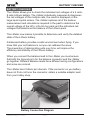
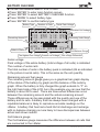
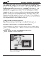
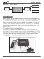
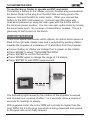
INSTRUCTION MANUAL
Multimeter 7 in 1
- 01 -
www.skyrc.com
TABLE OF CONTENTS
TABLE OF CONTENTS
Introduction
Features
Set Contents
Battery Checker
Battery Internal Resistance
Watt Meter
Servo Tester
Tacheometer RPM
Temperature
Thrust Calculator
Product Specifications
Warranty And Service
03
04
04
06
08
10
12
13
14
15
16
16
CAUTION - Before you start
This is a sophisticated unit which will be an important tool in your
electric powered model program. Please be careful with it! And please
read this instruction manual thoroughly before operating.
Do not disassemble, modify or subject the unit to force impact.
Keep the i-Meter well away from dirt or water.
High power electrical systems pose dangers independent of devices
like the i-Meter and it is the user's responsibility to be familiar with these
dangers and take any necessary action to ensure safe use. Shorting a
rechargeable battery or a i-Meter connected to a rechargeable battery
or battery charger can supply huge currents and have serious
consequences including explosions, causing fire, damage to equipment
and personal injury.
There are risks associated with the potentially high currents measured
by the i-Meter. These include, but are not limited to, fire, burns and
personal injury. The user must be familiar with the relevant methods,
procedures and connection components before using or making any
connection.
Do not exceed a maximum of 60 volts for the main power pack (MPP)
Keep proper distance from propeller during measurement process.
www.skyrc.com
- 02 -
INTRODUCTION
INTRODUCTION
Thank you for the purchase of this SKYRC i-Meter. The SkyRC i-Meter
can carry out an enormous range of functions related to Electric
Powered models and has been designed with ease of use as a prime
objective. This Instruction Manual describes the scope of i-Meter and
how to make it work for you.
Input
Voltage
Port
LCD Display
Dot Matrix 128*64
Mode
Connector to
Temperature
Sensor Probe
Output
Connector to
Servo
Potentiometer Dial
to Control Servos,
ESC, other PW devices
- 03 -
Enter
Back
ESC
Optical
Tachometer
Sensor
www.skyrc.com
FEATURES
FEATURES
1. Battery Checker
2. Battery Internal Resistance
3. Watt Meter
4. Servo Tester
5. Optical Tachometer
6. Temperature Gauge
7. Thrust Calculator
SET CONTENTS
1
2
3
5
4
1. Input Cable
2. Battery Internal Resistance Cable
3. i-Meter
www.skyrc.com
- 04 -
4. Temperature Probe
5. Output Cable
FEATURES
The Main screen displays all the available functions. The desired
function can be accessed by highlighting the desired function by
pressing ‘MODE’ button, pressing the ‘ENTER’ button to select
that function.
B
I
W
S
T
T
T
S
A
N
A
E
A
E
H
E
T
T
T
R
C
M
R
T
T
.
T
V
H
P
U
ERY
RES
ME
O T
OME
ERA
ST
UP
I
T
E
T
T
C
C
S
E
S
E
U
A
H
T
R
T
R
R
L
ECKER
ANCE
ER
RPM
E
C...
MODE
B
I
W
S
T
T
T
S
A
N
A
E
A
E
H
E
T
T
T
R
C
M
R
T
T
.
T
V
H
P
U
MODE
B
I
W
S
T
T
T
S
A
N
A
E
A
E
H
E
T
T
T
R
C
M
R
T
T
.
T
V
H
P
U
ERY
RES
ME
O T
OME
ERA
ST
UP
I
T
E
T
T
C
C
S
E
S
E
U
A
H
T
R
T
R
R
L
A
N
A
E
A
E
H
E
T
T
T
R
C
M
R
T
T
.
T
V
H
P
U
ERY
RES
ME
O T
OME
ERA
ST
UP
I
T
E
T
T
C
C
S
E
S
E
U
A
H
T
R
T
R
R
L
ECKER
ANCE
B
I
W
S
T
T
T
S
ER
RPM
E
C...
A
N
A
E
A
E
H
E
T
T
T
R
C
M
R
T
T
.
T
V
H
P
U
A
N
A
E
A
E
H
E
T
T
T
R
C
M
R
T
T
.
T
V
H
P
U
ERY
RES
ME
O T
OME
ERA
ST
UP
I
T
E
T
T
C
C
S
E
S
E
U
A
H
T
R
T
R
R
L
C
S
E
S
E
U
A
H
T
R
T
R
R
L
ECKER
ANCE
ER
RPM
E
C...
ERY
RES
ME
O T
OME
ERA
ST
UP
I
T
E
T
T
C
C
S
E
S
E
U
A
H
T
R
T
R
R
L
ECKER
ANCE
ER
RPM
E
C...
MODE
ECKER
ANCE
B
I
W
S
T
T
T
S
ER
RPM
E
C...
A
N
A
E
A
E
H
E
T
T
T
R
C
M
R
T
T
.
T
V
H
P
U
MODE
B
I
W
S
T
T
T
S
I
T
E
T
T
C
MODE
MODE
B
I
W
S
T
T
T
S
ERY
RES
ME
O T
OME
ERA
ST
UP
ERY
RES
ME
O T
OME
ERA
ST
UP
I
T
E
T
T
C
C
S
E
S
E
U
A
H
T
R
T
R
R
L
ECKER
ANCE
ER
RPM
E
C...
MODE
ECKER
ANCE
ER
RPM
E
C...
MODE
- 05 -
B
I
W
S
T
T
T
S
A
N
A
E
A
E
H
E
T
T
T
R
C
M
R
T
T
.
T
V
H
P
U
ERY
RES
ME
O T
OME
ERA
ST
UP
I
T
E
T
T
C
C
S
E
S
E
U
A
H
T
R
T
R
R
L
ECKER
ANCE
ER
RPM
E
C...
www.skyrc.com
BATTERY CHECKER
BATTERY CHECKER
The i-Meter allows you to check the individual cell voltages of a 2 cells8 cells Lithium battery. The i-Meter individually measures & diagnoses
the cell voltages of the multiple cells, the result is displayed on the
large liquid crystal screen. The i-Meter replaces all of the tedious
measurement and calculations required in the past to determine the
overall voltage of the LiPo, LiFe & LiIon pack and the individual cell
voltages that determine the balance of the Lithium pack.
The i-Meter now makes it possible to determine and verify the detailed
state of the Lithium battery.
A balanced battery provides a safer environment when flying. If you
know that your cell balance is out you can address the issue.
The prevention of deteriorating cells over time, will improve the
efficiency and stability of the Lithium battery.
When you connect the balance lead to the i-Meter you must ensure
that both the Ground pin’s for the balance connector and the i-Meter
go together. Different Balance leads have different wiring configurations
and some are colored.
The i-Meter has 2.54mm pin intervals. If the connector on you battery
does not fit do not force the connector, obtain a suitable adaptor lead
from your hobby shop.
Battery Connection Diagram
www.skyrc.com
- 06 -
BATTERY CHECKER
Connect the balance lead to ‘VOLT PORT’
Press ‘ENTER’ to enter main function screen
Press ‘ENTER’ to select BATTERY CHECKER function
Press ‘MODE’ to select battery type
Press ‘ENTER’ to confirm battery type
Battery Type
Remaining Amount %
Balance Status %
L
1
3
5
7
5
6
3
i
)
)
)
)
7
9
.
Number of Cells
P
3
3
3
0
%
%
8
o
.
.
.
8
8
8
6
4
5
7
S
7
2
7
2
2
4
6
8
Serial Pack Voltage
3
)
)
)
)
.
3
3
3
0
1
.
.
.
5
8
8
8
9
4
5
7
V
7
9
8
E
F
X
0
8-3.85=0.031
Individual Cell Voltage
Remaining Volts Gauge
Cell Balance Gauge
The Highest Cell Voltage Lowest Cell Voltage Cell Voltage Differential
Serial voltage
Pack voltage of the whole battery (total voltage of all cells) is indicated
The number of serial cells
The total number of cells in the battery pack is indicated (6S as indicated
in the picture 6 serial cells). This is the same as the cell quantity.
Remaining amount fuel gauge
The remaining amount gauge gives you a graphical bar graph display
of the status of the battery by graph and the balance of the cells by
graph. When the battery is fully charged the graph extends to “F” on
the right hand side of the LCD. As in the example you can see that the
battery is about 50% used. There are times when differences occur
between the remaining amount and the actual remaining amount.
These differences can be associated with the quality and use of the
battery and its cells. A battery that has always been charged with a
reputable balancer is likely to reproduce accurate readings on the
i-Meter. A battery that has had a hard life full discharge and recharge
with no balance charging is more likely to have discrepancies between
actual and shown results.
Cell balance gauge
The Cell balance gauge measures the difference between all cells that
are connected to the i-Meter.
- 07 -
www.skyrc.com
BATTERY INTERNAL RESISTANCE
The difference is shown graphically between the cell that is showing
the highest cell voltage to the cell that is showing the lowest cell voltage
(largest cell voltage difference) indicated on the graph. When the cell
voltages read equal, the bar extends all the way to the right (O). This
indicates that the cells are all balanced to a satisfactory level. When
the cells have a difference in voltage the bar shortens and indicates
towards the left (X). In order to maintain long lasting battery life if the
balance gauge does not show a satisfactory cell balance then a cell
balancer should be applied to the pack before use. If the cell balance
indication is low after the battery has been used this can be normal and
charging should occur with a balance charger.
BATTERY INTERNAL RESISTANCE
The i-Meter has been created to give you the ability to make an
informed determination of what the true cell and pack ratings by
providing a useful measure, the cell internal resistance.
Connect battery to i-Meter via Voltage Port to power on the i-Meter
Using supplied cable (pitch 2.54mm) to measure individual internal
resistance
Press ‘MODE’ to select ‘INT. RESISTANCE’ function
Press ‘ENTER’ to confirm selection
Int.Resietance
Res:
39
mohm
Connection Diagram for Measurement of Battery
Internal Resistance
www.skyrc.com
- 08 -
BATTERY INTERNAL RESISTANCE
Once we have an idea of the internal resistance of a cell we can then
use that to determine how efficient our power setup is as well as
knowing how much power is being turned to heat in the battery pack
and additionally know how much the voltage can potentially drop under
load.
B
I
W
S
T
T
T
S
A
N
A
E
A
E
H
E
T
T
T
R
C
M
R
T
T
.
T
V
H
P
U
ERY
RES
ME
O T
OME
ERA
ST
UP
I
T
E
T
T
C
C
S
E
S
E
U
A
H
T
R
T
R
R
L
ECKER
ANCE
Int.Resietance
Res:
ER
RPM
E
C...
39
mohm
Let it be stated that there is no perfect test for cell internal resistance.
Due to the nature of batteries, cells exhibit characteristics of resistance,
capacitance and inductance of which all contribute to the measured
internal resistance. Internal resistance can vary considerably even
within the same cell, this makes the task of determining the internal
resistance a lot harder.
Factors effecting resistance readings:
Contact corrosion
While not actually part of the cell itself, having dirty contacts to the cells
can make a noticeable difference in the resistance. Wiping clean the
contacts can improve contact resistance by 10 or more milliohms.
Cell temperature
For many cell chemistries the resistance of the pack decreases initially
from room temperature to a certain level (perhaps 45C) after which the
resistance of the pack will increase again. Lithium cells in particular
suffer poor cell resistance near 0C.
Cell charge
Generally the closer to a full charge a cell is the lower the internal
resistance.
Cell age
As cells become older their internal resistance tends to increase.
The i-Meter has been built to allow cells to be tested under a known
set of loads which will facilitate comparisons.
- 09 -
www.skyrc.com
WATT METER
PRECAUTIONS
1. Do not leave a cell connected to the i-Meter for more than five
minutes.
2. Be aware that although the i-Meter only takes small samples from
the battery pack, the voltage will be reduced. Make sure you check
your pack balance.
3. Avoid plugging the cell in reverse polarity. The i-Meter can cope with
a reversed connection for a few seconds but it’s still better not to do
it in the first place.
4. Do not connect more than 5V to the cell inputs, again, the IRM can
cope for a few seconds but it’s best not to do it!
WATT METER
This function measures Current (Amps), Peak current, Voltage (Volts),
Power (Watts), Energy(Watt-Hours) and Charge(Amp-Hours) values for
you, in real-time, for the circuit in which you connect it.
Battery
Pack
C
P
V
W
P
E
C
U
E
O
A
E
n
h
W
R
A
L
T
A
e
a
A
R
K
T
T
K
r
r
T
E
(
A
A
(
g
g
T
N
C
G
G
W
y
e
T
)
E
E
)
:
:
METER
: 35.11
: 52.11
: 25.13
: 882.3
: 1309.
82Wh
3.2Ah
A
A
V
1W
2W
Speed
Controller
Motor
i-Meter is activated when the battery is connected to the unit.
Press ‘MODE’ to select ‘WATT METER’ function
Press ‘ENTER’ to confirm selection
Now you can stop wondering what's going on with your electric model
and get answers that allow you to apply science to your hobby. The
precise measurements you collect will help you fine tune your model
to get all the performance that you paid for.
With watt meter function, it is now easy to determine things like:
Flight time
Current through an ESC and motor
ESC, BEC and motor efficiencies
Charge put into and removed from a battery and the performance of
battery chargers
Battery health
Why power is lost during acrobatics or extreme conditions
www.skyrc.com
- 10 -
WATT METER
Effect of gearing and propeller size and shape on power consumption
and battery currents
Effects of modifications, age and damage on many electrical system
components
Clever hobbyists will discover new applications to further improve
electric model performance.
The following are some examples of meter connections. Many other
arrangements and uses are possible
Testing Loads (e.g. motors)
Battery
Pack
C
P
V
W
P
E
C
U
E
O
A
E
n
h
W
R
A
L
T
A
e
a
A
R
K
T
T
K
r
r
T
E
(
A
A
(
g
g
T
N
C
G
G
W
y
e
T
)
E
E
)
:
:
METER
: 35.11
: 52.11
: 25.13
: 882.3
: 1309.
82Wh
3.2Ah
A
A
V
1W
2W
Speed
Controller
Motor
Battery on SOURCE side, Electronic Speed Controller (ESC) and
motor on LOAD side, with ESC on, the meter shows the current into the
motor, voltage and power at the battery and accumulates the charge
(Ah) while the motor is running.
Battery Charging
Battery
Charger
C
P
V
W
P
E
C
U
E
O
A
E
n
h
W
R
A
L
T
A
e
a
A
R
K
T
T
K
r
r
T
E
(
A
A
(
g
g
T
N
C
G
G
W
y
e
T
)
E
E
)
:
:
METER
: 35.11
: 52.11
: 25.13
: 882.3
: 1309.
82Wh
3.2Ah
A
A
V
1W
2W
Battery
With a battery charger on the SOURCE side and battery pack on the
LOAD side, the meter shows the charging current into the battery, the
voltage and charging power at the battery and accumulates the charge
(Ah) into the battery.
Battery Discharging
Battery
Pack
C
P
V
W
P
E
C
U
E
O
A
E
n
h
W
R
A
L
T
A
e
a
A
R
K
T
T
K
r
r
T
E
(
A
A
(
g
g
T
N
C
G
G
W
y
e
T
)
E
E
)
:
:
METER
: 35.11
: 52.11
: 25.13
: 882.3
: 1309.
82Wh
3.2Ah
A
A
V
1W
2W
Discharge
Load
When the battery is discharged, the meter indicates the total charge
(Ah) the battery delivered to the load as well as current, voltage and
discharging power.
- 11 -
www.skyrc.com
SERVO TESTER
Receiver & Servo Testing
Battery
Pack
C
P
V
W
P
E
C
U
E
O
A
E
n
h
W
R
A
L
T
A
e
a
A
R
K
T
T
K
r
r
T
E
(
A
A
(
g
g
T
N
C
G
G
W
y
e
T
)
E
E
)
:
:
METER
: 35.11
: 52.11
: 25.13
: 882.3
: 1309.
82Wh
3.2Ah
Servo 1
A
A
V
1W
2W
Reciver
Servo n...
SERVO TESTER
Servo testers are very useful for exercising your servos and Electronic
Speed Control (ESC) without the need to turn on your transmitter, and
you do not even need your receiver. The servo tester will put out a
signal just like the signals normally sent by your receiver to the servos
or ESC. The dial knob on the servo tester will change the signal just
like moving your transmitter stick would change the signal going to a
servo or ESC.
To use the tester to evaluate a servo
Connecting a battery to the i-Meter volt port. Plug a servo into the
servo port. The servo can be controlled with the adjustment dial under
Manual Mode. Press ‘MODE’ button once to set the PPM signal to auto.
The servo tester will use 1520us as centre and automatically output
cycling signal to move the servo arm back and forward.
www.skyrc.com
- 12 -
TACHEOMETER RPM
To use the Servo Tester to operate an ESC and motor
Connecting a battery to the i-Meter volt port. Another plug connected to
the Servo Tester is the plug from the ESC that normally goes to the
receiver. Connect the ESC to motor leads. When you connect the
battery to the ESC it will power up. It should react the same way
does when powered up using the radio gear with the throttle stick in
the minimum power position. You can now spin up the motor by turning
the servo tester knob. No receiver or transmitter is needed. This is a
great way to test motors on the bench.
TACHEOMETER RPM
There is an optical tachometer within i-Meter. An optical tacho sensor is
fitted to the right side i-Meter case and is activated by pointing i-Meter
towards the propeller at a distance of 10 and 20cm from the propeller.
Connect battery to i-Meter via Voltage Port to power on the i-Meter
Press ‘MODE’ to select “TACHOMETER RPM”
Press ‘ENTER’ to confirm the function
Press ‘MODE’ again to change the range of 1-5 blades
Press ‘ENTER’ to start RPM measurement
2
TACHO METER
Blades
tacho:
5520
rpm
peak:
5600
rpm
10-20cm
The fluctuating light caused by the rotation of the propeller is sensed
and counted over a period of either 1 or 2 seconds. Allow a couple of
seconds for readings to steady.
With a geared motor, the motor RPM will normally be higher than the
prop. RPM, but it is the prop rpm which is being measured and quoted,
so the gear ratio is not really relevant.
- 13 -
www.skyrc.com
TEMPERATURE
Please DON’T use optical tachometer with fluorescent lighting which
will give false readings, such as 3000 or 3600 rpm.
The optical RPM sensor will function over a large range of propeller
sizes, RPM and lighting conditions. It has even able to measure 40mm
diameter model boat props spinning in the air. Experiment with different
sensor positions. In some cases, best results may be achieved by
testing in the shade. With the motor running, move the optical sensor
to about 10~20 cm from the propellers, taking all due care. Small
propellers may require closer positioning. The number of propeller
blades should also be set. Wrong setting will affect RPM readings for
the optical tachometer. For example, fitting a three bladed propellers,
but leaving the i-Meter blade figure at 2 would cause the optical
tachometer to read 50% high.
TEMPERATURE
There is a temperature sensor available, so you can monitor the
temperature of battery, motor, electronic speed controller, etc. When
no sensor is connected, display will indicate 0.0°C and 32°F
Connect temperature probe to i-Meter
Press ‘MODE’ to select “TEMPERATURE”
Press “ENTER” to confirm selection
Current Temperature
Celsius
TEMPERATURE
Current
33C
89F
50C
Peak
122F
Peak Value
Celsius
www.skyrc.com
Current Temperature
Fahrenheit
Peak Value
Fahrenheit
- 14 -
THRUST CALCULATOR
THRUST CALCULATOR
The thrust calculator can estimate the thrust of an airplane, there are
many variances and some known factors.
Lets assume we have an airplane and this is its first flight. We know the
size of the propeller and we can do a static full throttle rpm check with a
tachometer on the ground. We can now add these known figures into
Thrust Calculator. By the fact that you can verify thrust it becomes
possible, to estimate the general power of the airplane in advance.
This will give you more knowledge about your plane and the power
characteristics to make your first flight less challenging and safe, after
all you may have other flight characteristics to deal with. This should
help you to estimate flight take off distances, recovery from a stall. For
more experienced pilots this will enable them to calculate if the plane is
going to be able to hover. It can show you what changes to the power
calculation will be affected by a different size propeller.
Propeller Length (inch)
propeller's Effectiveness
Coefficient
Propeller Revolution
RPM (Revolutions
Per Minute)
T
D
C
B
R
H
i
F
l
P
R
a
:
a
M
UST CALC
meter: 0
1
des:
2
:
1
Thrust:
.
Number of Blades
10.00
.00
1000
1.553Kg
3.424Lb
CF (Propeller's Effectiveness Coefficient Table)
Manufacturer
Standard propeller
APC propeller
APC SF
APC W propeller
MenzS propeller
Bambula propeller
Bolly clubman
Cox
GWS HD
GWS RS (SF)
Smart
Zinger Wood
CF
1.00
1.06
1.50
1.09
1.03
1.02
1.04
1.10
0.75
1.10
1.02
1.00
- 15 -
www.skyrc.com
PRODUCT SPECIFICATIONS
The static thrust calculation is taken from the October 86 AMA magazine,
air density is based on 29.92 in Hg, and propeller pitch is not used in this
calculation. Practical tests revealed very little if any change in thrust due
to pitch variation at the same RMP.
It is believed that this is partly due to any increase in thrust being negated
by blade stalling and a more turbulent influx area with increased pitch.
This obviously only applies to static conditions, not flying conditions.
PRODUCT SPECIFICATIONS
Max input voltage: 60V
Voltage measurement range: 2-8S LiPo/LiFe/LiIon
Voltage display resolution: 0.001V
Volt Port: 2.54mm pitch pins, 9 pins
Max current: 100A
Shunt resistance:0.001ohm
Displayed resolution A: 0.01
Temperature resolution: 1 Celsius / 1 Fahrenheit
PPM signal output: 750uS – 2150uS
Number of propeller measurable : 1 to 5
Propeller rotating range: 1-60000RPM
Dimension: 95.3x72.8x21.5mm
Net Weight: 85g
WARRANTY AND SERVICE
We guarantee this product to be free of manufacturing and assembly
defects for a period of one year from the time of purchase. The warranty
only applies to material or operational defects, which are present at the
time of purchase. During that period, we will repair or replace free of
service charge for products deemed defective due to those causes.
You will be required to produce proof of purchase (invoice or receipt).
This warranty is not valid for any damage or subsequent damage
arising as a result of misuse, modification or as a result of failure to
observe the procedures outlined in this manual.
SPECIFICATIONS ARE SUBJECT TO CHANGE WITHOUT NOTICE.
Manufactured by
SKYRC TECHNOLOGY CO., LTD.
www.skyrc.com
www.skyrc.com
- 16 -


![INSTALL GUIDE OEM-IDS(RS)-BM1-[ADS-BM1]-EN](http://vs1.manualzilla.com/store/data/005803017_1-bfa667bd4ebc7540cfa057e535ebd2e9-150x150.png)