1
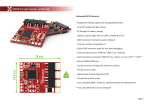
MC160 Servo Controller
Robot-Solutions, LLC
Robot-Solutions 2013
Users Guide
RSMC160
www.robot-solutions.com
Table of Contents
Specifications ................................................................................................................ 1
Overview ........................................................................................................................ 2
Factory Default .............................................................................................................. 3
Customization .............................................................................................................. 4
Channel Mixing (x) ....................................................................................................... 5
Input Control Curve (C) ................................................................................................ 5
Variable Brake (B) ....................................................................................................... 5
R/C input dead band (i)................................................................................................ 5
Minimum Drive (M) ...................................................................................................... 6
Power Slew Rate (s) .................................................................................................... 6
R/C input calibration .................................................................................................... 6
Saving custom settings (w) .......................................................................................... 7
User Interface ................................................................................................................ 8
Internal Register Summary......................................................................................... 10
Internal Register Description ..................................................................................... 13
Brake (B) ................................................................................................................... 13
Baud Rate (b) ............................................................................................................ 13
R/C Input Curve (C) ................................................................................................... 13
Copy Parameters (c).................................................................................................. 13
Derivative (velocity) Gain (D) ..................................................................................... 14
Error Dead Band (d) .................................................................................................. 14
Back-EMF Factor (E) ................................................................................................. 14
Encoder value (e) ...................................................................................................... 14
Input Factor (F) .......................................................................................................... 15
Temperature Protection Override (f) .......................................................................... 15
Integral Gain (I) .......................................................................................................... 15
R/C Input Dead Band (i) ............................................................................................ 15
Feedback Select (J) ................................................................................................... 15
Control Input Select (j) ............................................................................................... 16
Local Echo Option (l) ................................................................................................. 16
Minimum Drive (M) .................................................................................................... 17
Servo Mode (m) ......................................................................................................... 17
R/C Pulse High Limit (N) ............................................................................................ 17
R/C Pulse Low Limit (n) ............................................................................................. 18
Proportional (Position) Gain (P) ................................................................................. 18
Position Set Point (p) ................................................................................................. 18
Factory Preset (Q) ..................................................................................................... 18
Servo Update Rate (r)................................................................................................ 19
Power Slew Rate (s) .................................................................................................. 19
Torque Limit (T) ......................................................................................................... 19
Torque Set point (t) .................................................................................................... 20
Robot-Solutions 2013
Users Guide
RSMC160
www.robot-solutions.com
Unit Amount Minimum Move (U) ................................................................................ 20
Unit Amount Manual Move (u) ................................................................................... 20
Velocity Limit (V) ........................................................................................................ 20
Velocity Set point (v) .................................................................................................. 20
Write User Memory (w) .............................................................................................. 21
Channel Mixing (x) ..................................................................................................... 21
Menu Items .................................................................................................................. 21
Output Drive values .................................................................................................... 22
Control Period ............................................................................................................. 22
Position & Encoder values ......................................................................................... 22
Velocity ........................................................................................................................ 22
Torque .......................................................................................................................... 23
Tuning, discovering servo PID Gain values .............................................................. 24
Off Mode (0): ............................................................................................................. 24
PWM Mode (1):.......................................................................................................... 24
Torque Mode (2): ....................................................................................................... 24
Velocity Mode (3): ...................................................................................................... 24
Position Mode (4):...................................................................................................... 25
Indicators and Outputs ............................................................................................... 25
Status LED ................................................................................................................ 25
Temp LED ................................................................................................................. 25
COAST LED (Aux, Left & Right) .................................. Error! Bookmark not defined.
FWD/REV LED (Aux, Left, Right) ................................ Error! Bookmark not defined.
Limitations and Warrantees ....................................................................................... 26
Support ........................................................................................................................ 26
General Guidelines...................................................................................................... 26
Appendix A: System Software Updates .......................... Error! Bookmark not defined.
Appendix B: Input methods ....................................................................................... 27
Control Input Methods ............................................................................................... 27
Serial ...................................................................................................................... 27
R/C control ............................................................................................................. 27
Analog Signal ......................................................................................................... 27
Step & Direction ..................................................................................................... 27
Feedback Input Methods ........................................................................................... 28
Encoder .................................................................................................................. 28
Analog Signal ......................................................................................................... 28
Appendix C: Interface Wiring Information ................................................................ 29
Analog ....................................................................................................................... 29
Step & Direction ......................................................................................................... 30
Incremental Encoder.................................................................................................. 31
Manual Move ............................................................... Error! Bookmark not defined.
Appendix D: Example applications............................................................................ 32
Robot-Solutions 2013
Users Guide
RSMC160
www.robot-solutions.com
Factory Default .......................................................................................................... 32
Giant R/C Servo......................................................................................................... 33
Set Up & Tuning ..................................................................................................... 33
CNC (Stepper motor) servo ....................................................................................... 35
Mounting instructions and enclosure drawing………………………………………………36
Robot-Solutions 2013
Users Guide
RSMC160
www.robot-solutions.com
Specifications
The MC160 uses custom software to implement a 2 channel high-powered servo
system. The servo uses a quadrature encoder feedback mechanism to control torque,
velocity, and position of the output. It includes the capability to control a relay (relay not
included) from a third channel.
Enclosure size 7.3” x 4.3” x 1.2” not including fan.
Weight with enclosure: 1.5 lbs.
Dual main channels 160 Amps each
Current limiting on both main channels.
Thermal protection.
8-42v battery operation1.
Large power connector accepts #10 – 32 screws allowing for secure connections
using ring terminated wires.
Full RS232 serial command and setup.
Standard RS232 communications N81- from 4800 up to 115200 baud.
Default baud rate is 115,200 N81.
Multiple-operating modes:
o Off
o Normal PWM
o Torque
o Velocity
o Servo-Winch-Position
o Servo-Position
Thermal power monitoring and limiting.
User selected control inputs: Serial Command, Analog Voltage, R/C Pulse or
Step & Direction (CNC).
User selected servo feedback: Encoder or Analog Voltage.
User adjusted hardware current limiting (Potentiometer adjustment). One
potentiometer controls both main channels.
User adjustable software current limiting Torque limit in servo mode.
Robust signal processing for smooth, reliable fail-safe operation.
Indicator LED’s show power, over-current, and board status.
1 Note the board is powered directly from the main power terminals. Ground is provided to the logic section via
direct connection to the main power ground terminal.
Robot-Solutions 2013
Users Guide
MC160
www.robot-solutions.com
-1-
Overview
The MC160 brushed Motor Controller provides a flexible platform for controlling brushed
DC motors. The controller has two power drivers built into it with discreet control.
The default factory configuration supports operation with R/C radios for traditional
combat and remote control robotics applications. The factory default is easily modified
and stored in non-volatile (configuration) memory and is restored whenever power is
applied. In factory default mode the Left R/C channel controls forward/reverse motion
and the Right R/C channel controls steering.
All configuration and control parameters are set via serial menus and configuration
strings. The serial interface supports standard RS232 signaling from 4800 to 115200
baud using a normal DB9 serial cable. The entire unit may be configured and controlled
via a PC or Laptop using a terminal emulator (e.g. Hyperterm or Terraterm).
The MC160 supports a variety of servo operation modes (position, velocity, torque &
servo) using a variety of input and feedback methods. The MC160 accepts the
following control input signals: serial commands, Analog voltage (0-5v), Radio Control
signaling or Step & direction. For servo feedback the MC160 accepts either analog
voltages (0-5v potentiometer) or quadrature encoders. Inexpensive industrial encoders
can be obtained from www.usdigital.com. The relationship between the various control
inputs output are set by serial configuration commands and the serial interface is always
available for adjusting parameters regardless of the operating mode.
Some examples of systems possible with the MC160
1. A simple radio controlled motor controller. Radio receiver power is supplied by
the MC160 BEC. You do not need an external radio battery.
2. A large R/C style servo can be created by combining the R/C control input with
the analog voltage feedback.
3. Using R/C input and encoders enables velocity control which is superior for the
handling of remote control robots.
4. Serial input with encoder feedback enables machine controllable subsystems,
such as steering or brake controllers in large vehicles.
5. Step & Direction input with encoder feedback simulates large high powered step
motors with inexpensive PMDC motors. The step & direction feedback interfaces
directly with CNC software.
The Controller automatically loads the last saved or recalled set upon power up,
supporting unattended operation.
Robot-Solutions 2013
Users Guide
MC160
www.robot-solutions.com
-2-
Factory Default
As shipped from the factory the MC160 firmware will boot into a default minimal function
mode. The feature set is as follows:
1.
2.
3.
4.
5.
6.
7.
8.
Basic PWM control: 95%2 reverse to 95% forward power.
R/C input control, +/- 10us dead band.
Single stick (channel mixing).
Normal R/C calibration.
Mild input curve.
100% brake with neutral command
.1 second power slew rate
Serial communications set at 115200 baud.
At any time the user can reset the unit to the factory values with a simple command via
the terminal interface. The MC160 uses a standard DB9 RS232 cable and should
connect to any PC or laptop computer. Newer computers may only have USB
connectors and an inexpensive USB to Serial adapter would be required. Connect a
terminal emulator (e. g. Hyperterm) with the following settings:
115200 baud
8 bit no parity
One stop bit
At the prompt type in the following characters:
@0sQ0<cr> (<cr> represents the ENTER key.)
If you desire single stick control type in the following string instead:
@0sQ1<cr>
NOTE: Values are not stored in non-volatile memory by default. You can test these
modes out before you save them but you need to write the values out before they
“stick”. The command to do this is:
@0sw0<cr>
The non-volatile store and how to use it is described in a later section.
2
For reasons related to the hardware current limiting logic 100% power is not allowed.
Robot-Solutions 2013
Users Guide
MC160
www.robot-solutions.com
-3-
Customization
There are a variety of customizations that can be applied to the MC160:
1.
2.
3.
4.
5.
6.
7.
8.
Channel Mixing for single or dual stick operation
Calibration of R/C inputs
Adjustable control curves
Control Dead band
Minimum Drive values for output
Variable braking when neutral
Variable power slew rate
Up to four different sets of customizations may be stored and recalled.
What follows are customizations that apply to the default factory configuration. These
registers are described in detail in this section and primarily apply to simple R/C control
of power – a typical remote control robot configuration. There is a complete description
of all customization registers further on in this document under Internal Register
Description.
In general, configuration parameters are entered in the following form:
@{channel}{s,g,a}{register}{value}
Each command starts with the @ character. The second character is a number
indicating which channel. The channels are numbered as follows:
0
1
2
Left R/C input or Power output
Right R/C input or Power output
Aux R/C input (flip or relay control)
The third character indicates the operation:
s = Set the value into the register
g = Get the value stored in non-volatile memory
a = Get the actual current operating value
Note: for some commands the programmed value is not acted upon until the system is
reset, hence the ‘a’ modifier.
The fourth character is the “register” that contains the value being adjusted.
The final field is a signed decimal number (i.e. it can be negative). If this number is left
out a ‘0’ will be used instead.
All commands are terminated with a Carriage return (enter) <cr>.
Robot-Solutions 2013
Users Guide
MC160
www.robot-solutions.com
-4-
A typical command might be “Set Left Channel Drive 250” and would look like this:
@0sd250
The command to read the drive for the Left Channel and print it out would look like this:
@0gd
Channel Mixing (x)
Channel mixing is a global value not associated with R/C input channels or PWM output
channels. The “channel” value is ignored. The value can be either 0 (Tank) or 1
(Mixed). Mixing uses the Left channel as throttle and mixes in the Right channel as
steering. This is commonly used to implement single stick control for steering & throttle
in remote control robots.
@0sx0 – Disable Mixing
@0sx1 – Enable Mixing
Input Control Curve (C)
A variable exponential control curve can be applied to the R/C input. The curve value
applies to all channels. The amount ranges from 0, which is flat, to 7, which represents
a fairly aggressive curve.
@0sC{0-7}
The factory default is a mild curve of 3.
Variable Brake (B)
When control sticks are in neutral position the MC160 can apply a variable amount of
braking effort. Braking varies from 0 (coasting) to 31 (100%). Braking is regenerative
and will generate current to re-charge the supply battery. The string to set the brake
amount:
@{0, 1 or 2},sB{0-31}
Braking is specified independently for the Left, Right or Aux channels, hence the 0, 1 or
2 in the first field.
The Factory default is 100% brake
R/C input dead band (i)
Specifying the R/C input dead band can help prevent jitter when control sticks are in
neutral position. The dead band is specified in +/- microseconds.
@{0, 1, 2, or 3}si{0-63}
Robot-Solutions 2013
Users Guide
MC160
www.robot-solutions.com
-5-
Factory default value is +/- 10 microseconds.
Minimum Drive (M)
Often robotic drive systems have significant friction to overcome before the robot
moves. Minimum drive helps compensate for that by boosting the PWM values.
@{0, 1, 2}sM{0-255}
Note: 10-25 are normal values
The best way to set this parameter is to use the serial interface to display drive values
and move the trim/stick until the drive train just starts to move; then record the values
and use that as a starting point.
Factory default is 0.
Power Slew Rate (s)
For high power systems suddenly changing power levels can introduce shock and or
large current draws. The former is hard on the mechanical system and the latter can
cause trouble with batteries. The MC160 has a variable power slew function that is only
active in PWM mode. The slew function specifies the time, in 1/10th second units; it
takes to move the output power from –100% to +100% (full reverse to full forward). Too
much slew can make the operation sluggish. For large kinetic energy weapons,
however, a large slew is needed to limit the inrush or regenerative braking currents as
the device accelerates or decelerates.
@{0, 1, or 2}ss{0-100}
Note: a typical value is 0 to 10 for drive outputs.
The factory default is 1.
Note: Proper slew rate operation depends upon the default internal update rate of 50 Hz
and works only in the default PWM mode. Please do not modify the update rate if you
use this function. If you do modify the update rate be aware that the slew values will
need to be scaled appropriately.
R/C input calibration
The MC160 can be calibrated for the particular range of R/C pulse widths supplied by
the radio. Calibration can be done explicitly, where the user specifies the minimum and
maximum control pulse widths in microseconds, or calibration can be done by
discovery. In discovery mode the control sticks are moved to their extremes, and the
software records the minimum and maximum values.
To enter and exit discovery calibration mode:
Type in “Cal<cr>” on the serial port.
Robot-Solutions 2013
Users Guide
MC160
www.robot-solutions.com
-6-
Calibration mode is indicated by a 1 second periodic “wink” and a text message is
printed to the serial port. To exit calibration mode do one of the following:
Type the ESC character on the serial interface
Exit mode is indicated by the status LED returning to its previous flash pattern and a
short message printed to the serial interface.
NOTE: Once calibrated, the values need to be saved in one of the user configuration
slots or they will be lost the next time the controller’s power is cycled.
Factory default values for all channels:
Minimum:
1.095 milliseconds
Maximum: 1.950 milliseconds
Although the allowable range is anywhere from 0 to 32 milliseconds, the controller will
only recognize pulse width values between 0.850 and 2.150 milliseconds long. The
recognized values are relaxed enough for all known R/C pulse gear including IFI robot
controllers.
Saving custom settings (w)
All settings and calibration is performed on the running system. When power is
removed, the current values are lost. The MC160 provides four non-volatile memory
slots for storing parameters. Four sets can be stored and the MC160 will restore the
last accessed slot whenever rebooting. Settings and calibrations are stored with the
following command string:
@{0, 1, 2 or 3}sw
When power is lost and restored, the MC160 will restore the last slot stored. If an
alternate slot is needed it can be recalled with the following command:
@{0, 1, 2 or 3}gw
After recall, if the power is lost, the MC160 will restore the last recalled or stored slot.
Robot-Solutions 2013
Users Guide
MC160
www.robot-solutions.com
-7-
User Interface
The host controller communicates through a standard DB9F RS232 serial port,
compatible with standard computers. In addition to entering in data in command
packets, the RS232 port supports basic line editing with the backspace key. The control
interface also has a simple menu system that allows immediate feedback about servo
performance.
Below is representative of the text printed to the serial port at power on. It includes
many of the commands and settings available. Please refer to appendix A for a
complete list of parameters.
Some terminal programs may need to be configured to show the output correctly. If you
are not seeing the below example then check your terminal programs setting for how it
sends and received carriage returns.
MC160
p<cr>
Parameters
r<cr>
Reset Servo (E-Stop)
a{#}<cr>
Analog, # = Repetition Rate in responses per second
d{#}<cr>
Drive
e{#}<cr>
Encoder
S{#}<cr>
Streamlined Parameters
t{#}<cr>
Temp
v{#}<cr>
Velocity
@<adx><mod><reg><val>
Command Packet<cr>
<adx> 0 (left), 1 (right), 2 (aux)
<mod> s (set), a (actual), c (current)
<val> Decimal number (default = 0)
<reg> m: 0=off, 1=pwm, 2=torq, 3=vel, 4=Winch, 5=Position, 6=Alt
M: Minimum Drive value to move output. (Default=0)
d: Position Error Deadband (Default =255)
f: Thermal protection on=1/off=0 (volatile, can’t be stored)
p: Position Setpoint
u: Unit amount (for manual move)
U: Unit amount filter
r: Loop Rate (0-255)
t: Torque Setpoint (+/-255)
T: Torque Limit (0-255)
v: Velocity Set point
V: Velocity Limit
w: Write values to EEPROM
l: 0 no echo, 1 echo, 2 Machine I/O
c: copy from <adx> to <val>
? - help
>
On a unit with a corrupt or blank configuration the default-operating mode is 115,200
baud with local echo enabled. The local echo option repeats every character received
so that the user can see what they are typing.
Robot-Solutions 2013
Users Guide
MC160
www.robot-solutions.com
-8-
The status of the non-volatile storage can be determined by the status LED on the
MC160. It has two states:
1. Blinking approximately once a second
Normal operation, non-volatile storage valid.
2. Blinking rapidly, approximately four times a second
Non-volatile storage corrupt, or never programmed after erase.
Examples of commands:
When fresh programmed, the non-volatile store will be corrupt and light flash rapidly and
the default baud rate is set to 115200. Change it to 19200:
>@0sb2
>@0sw
>@1gb
>@1ab
Set baud rate #2 (19200)
Write configuration to EEPROM user slot 0.
Reports stored baud rate (2).
Reports operating baud rate (5).
The actual baud rate is the old value, 115200, until the unit has been power-cycled.
The current baud rate is the programmed value. Reset the unit to load the new baud
rate.
Normally, the MC160 interface prints information in response to user input. However,
for most menu items (not @ registers), an optional repeat modifier may be specified
which causes the MC160 to periodically print out information. The repeat modifier is
just a number after the single character command. The number is the repetitions per
second.
Robot-Solutions 2013
Users Guide
MC160
www.robot-solutions.com
-9-
Internal Register Summary
Robot-Solutions 2013
Users Guide
MC160
www.robot-solutions.com
- 10 -
Function
Servo
B
c
d
D
e
E
F
I
j
J
L
M
m
p
P
r
s
t
T
u
Brake
Copy values
Position Error Dead band
Velocity Error Gain
Position (encoder)
Back-EMF factor
U
v
V
Input Factor
Integral Error Gain
Input Select
Feedback Select
Position Limit
Minimum Drive
Mode
Position Set point
Position Error Gain
Servo loop rate
Power Slew
Torque Set point
Torque Limit
Unit amount for manual move
Unit amount for minimum
move.
Velocity Set point
Velocity Limit
Radio
C
i
n
N
x
Input Curve
Input Dead band
Low Limit
Upper Limit
Mixing
Misc
b
f
Baud Rate
Temperature Protection
Robot-Solutions 2013
Users Guide
Lower
Upper
Default
Applies
to
0
31
31
-255
-32768
-2.00E+09
-32768
255
32768
2.00E+09
32768
0
0
0
0
-32,000
-32768
0
0
-2.00E+09
-255
0
-2.00E+09
-32768
0
0
-255
-255
-32768
32,000
32768
3
1
2.00E+09
255
6
2.00E+09
32768
255
100
255
255
32768
8
0
0
0
0
1
0
0
10
0
0
0
0
CH 0-2
CH 0-2
CH 0-2
CH 0-2
CH 0-2
CH 0-2
CH 0-2
CH 0-2
CH 0-2
CH 0-2
CH 0-2
CH 0-2
CH 0-2
CH 0-2
-32768
-32768
-32768
32768
32768
32768
0
0
0
CH 0-2
CH 0-2
CH 0-2
0
0
850
850
0
31
63
2150
2150
1
0
0
5
1
MC160
CH 0-2
Global
CH 0-2
CH 0-2
CH 0-2
CH 0-2
Global?
RC 0-3
RC 0-3
RC 0-3
Global
Global
Global
Notes
0-100% braking at zero drive only.
Funky: just copy servos
11.5 binary fraction:
32 bit number
Used to estimate torque
12.4 Number; Multiplier for Normalized R/C value used as set points for various servo
modes
11.5 binary fraction:
Serial, Radio, Analog, or Step/Dir
Encoder/Analog
Not Implemented (yet)
Minimum PWM drive to move output (De-dead band)
0 - Off, PWM, Torque, Velocity, Winch, Position, AltWinch, SpinMode1, SpinMode2, Relay
Input to Position control loop
11.5
Loop rate in milliseconds, 0 = off
0-10 sec by .1 sec; Time to slew from -100% to 100% power
Input to Torque control loop
0-100% pwm.
In Encoder Counts (position error dead band for Step/Dir interface)
In Encoder Counts
Input to Velocity control loop
Encoder counts/loop
+/- uSeconds around zero
R/C Pulse width
R/C Pulse width
Left/Right Off, On.
4800, 9600, 19200, 38400, 57600. and 115200
Volatile, enabled after reset.
www.robot-solutions.com
- 11 -
*
l
Q
w
Function
Enter Boot-loader
User Interface Mode
Compatible Preset
Write/Load values to/from
EEPROM
0
0
2
1
Applies
to
n.a.
Global
Global
0
3
Global
Lower
n.a.
Upper
n.a.
Default
n.a.
Notes
Not implemented
no echo, echo, machine mode
R/C PWM mode, straight or mixed
s = set, a = current slot, g = get slot
User Interface/Menu
"Cal"
Enter R/C Calibration mode
@
Enter/Print register values
d
PWM Drive
e
Encoder count
ESC
Exit R/C Calibration mode
i
R/C input in uS
I
R/C input, Normalized
p
Print Parameters
r
Reset Servo (stop)
S
Streaming parameters
t
Temperature
v
Velocity (counts/loop)
NOTE: For the most up to date command info type ?<CR> into the serial interface for a list of all commands.
Robot-Solutions 2013
Users Guide
MC160
www.robot-solutions.com
- 12 -
Internal Register Description
The following is a summary of commands used to set and query internal registers of the
MC160. Most commands operate on channels and apply (or print) values. A few
commands have no register value. Please reference Customizations, under Factory
Defaults, above, for details of the register command format.
Brake (B)
Range: 0-31 representing 0% to 100% brake.
Default: 31
Only applies when output drive is neutral (0% drive) on channels 0, 1 and 2 (Left, Right
and Auxiliary).
Baud Rate (b)
Range: 0-5 representing the following baud rates:
0. 4800
1. 9600
2. 19200
3. 38400
4. 57600
5. 115200
Default: 5 (115200)
Changes to baud rate take effect after the system is reset by a power cycle. Channel
value must be 0, but is otherwise ignored. Remember to save new baud rate in User
Memory with the ‘w’ register.
R/C Input Curve (C)
Range: 0-7
Default: 3
Selects an exponential curve which modifies the R/C input signal. Curves are useful for
greater control of simple power based robots. 0 represents a flat line and 7 represents
an aggressive curve.
Copy Parameters (c)
Range 0-3
Copies the contents of registers for channel N to Y. Example to copy parameters from
the Left register bank to the Right:
@0sc1
Robot-Solutions 2013
Users Guide
MC160
www.robot-solutions.com
- 13 -
Derivative (velocity) Gain (D)
Range: 0-1023
Default: 0
Derivative gain is a 5.5 binary number that determines how strongly the servo attempts
to maintain a velocity set point.
See Tuning Servos, below, for more information about this value.
Error Dead Band (d)
Range: 0-255
Default: 0
Back-EMF Factor (E)
Range: 0-255
Default: 0
Back-EMF is used to estimate the torque. The back-EMF factor is calculated by
dividing 8196 by the maximum velocity at 100% drive (255). This is just an estimate as
many PMDC motors have non-neutral timing and thus different back-EMF factors in
reverse. If your motor has non-neutral timing, just take the average between forward
and reverse velocity (ticks/period)
This factor can also be used to compensate for friction. The way to do this is to set the
servo into the Torque mode with a torque set point of zero. Then adjust the Back-EMF
gain until the system feels frictionless. When too large, the output, when disturbed, will
accelerate. If too low, it will slow down and stop. When just right it will continue in the
same direction and speed indefinitely (e.g. "frictionless). Make sure you test at fairly
high velocities as the back-EMF values are inaccurate at low velocities.
Typical back-EMF factors are in the 8-30 range.
Encoder value (e)
Range: +/- 2 billion
Default: 0
This register contains the current encoder value, often thought of as position. By
writing this register the position can be set to any value. The value in this register will
be restored when loading user parameters. So, if you want the default, boot value to be
zero, then zero this register before saving user parameters.
The MC160 encoder input implements a 2X quadrature decoder. One multiplies the
encoder slot count (e.g. 64) by 2 to determine the total number of counts per revolution.
Robot-Solutions 2013
Users Guide
MC160
www.robot-solutions.com
- 14 -
Input Factor (F)
Range:
Default: 0
The number multiplied by the selected input method (R/C or Analog input) to generate
the appropriate control value. This number is divided by 32 after the multiplication so
fractional values may be specified. See Appendix B for more information on input
methods.
Temperature Protection Override (f)
Range: 0 & 1
Default: 0
This register allows temporary override of temperature fold back function within the
MC160. When set to 1 fold back is disabled and full power can be delivered regardless
of the heat-sink temperature of the power driver. This value is volatile, meaning it
cannot be saved and will be reset to zero after each power cycle.
Integral Gain (I)
Range: +/- 32,000
Default: 0
Integral gain is used in the PID calculation for correcting velocity errors. See Tuning
Servos, below, for more information about this value.
R/C Input Dead Band (i)
Range: 0-255us
Default: 10us
R/C input dead-band is specified in microseconds (us). The specified value will be
used +/- around the middle or zero value which is 1500us. The default value is +/- 10us
around 1500us.
Feedback Select (J)
Range:
0. Encoder
1. Analog Voltage (0-5v)
Default: 0 (Encoder)
The J registers selects the feedback method for the servo controller. Analog feedback
is typically a 10-100k ohm linear potentiometer connected between ground and +5v.
The encoder method uses standard, inexpensive, industrial quadrature encoders to
determine direction and speed of rotation.
See Appendix B for more details on input and feedback methods.
Robot-Solutions 2013
Users Guide
MC160
www.robot-solutions.com
- 15 -
Control Input Select (j)
Range:
0. Serial command
1. R/C input
2. Analog Voltage (0-5v)
3. Step & direction input
Default: 1, R/C input
See Appendix B for more details on input and feedback methods.
Local Echo Option (l)
Range:
0. No Echo
1. Echo typed characters.
2. Special Machine interface mode.
Default: 1, echo typed characters.
The serial interface includes a line editor that supports backspace and escape (cancel).
The editor can optionally disable character echo for machine interface (where a
computer simply sends commands, not expecting data returned). There is a third
method that facilitates machine communications while echoing the entire command line
AFTER it has been processed.
Besides echo & no-echo, there is a third mode that implements a machine friendly
interface to the @ commands. This interface does not echo received characters. After
processing the command the interface echo’s the original string, with the ‘@’ replaced
with a special character and post-pended with data, if any. The special characters are:
1. ‘!’
2. ‘*’
3. ‘#’
- Error response (i.e. didn’t recognize the command)
- Normal, Ok response (no data)
- Normal, OK response, data follows.
The Set Local Echo command is used to enter this mode and it can be saved in
EEPROM like other parameters. Specifically, the following will place the unit in the
special interface mode:
>@0sl2
*0sl2
Note the effect is immediate (i.e. the response is the new acknowledge string), but the
command still needs to be stored to be active after the next power up.
Example, Set Encoder value:
Send: @0se1234<cr>
Get: *se1234<cr>
Robot-Solutions 2013
Users Guide
MC160
www.robot-solutions.com
- 16 -
Example, Get Actual Encoder Value:
Send: @0ae<cr>
Get: #0se1234<cr>
Example, Get encoder value from invalid address:
Send: @2ae<cr>
Get: !2ae<cr>
Minimum Drive (M)
Range: 0-255
Default: 0
Minimum drive specifies an amount of drive to add to the output in order to overcome
drive train friction. See, Customizations, above for more details.
Servo Mode (m)
Values:
0. Off
1. PWM
2. Torque
3. Velocity
4. Position Mode using winch (no back-drive)
5. Position Mode (position with back-drive)
Default: 0, off.
Servo mode selects the operation of the servo. A description of each mode can be
found in Tuning Servos, below.
A note about Winch position mode: when a worm gear drive is used for a servo
transmission, the output cannot be back-driven. Torque on the output shaft cannot be
transmitted back to the servo motor. Winch drive recognizes this special case and
resets the PID Integral error term when the drive reaches the position set point.
Normally, the integral error term is needed to hold back-drivable servos in position once
the set point has been achieved.
R/C Pulse High Limit (N)
Range: 0-32,000us
Default: 1950us
The R/C pulse limits are the calibrated values for +/- 100% input. Normal R/C pulse
range is 1.0 to 2.0ms, with 1.5ms as the zero value. By selecting alternate high and low
values the range of -100% to 100% can be shifted and scaled. The default values are
suitable for most off the shelf R/C gear.
Robot-Solutions 2013
Users Guide
MC160
www.robot-solutions.com
- 17 -
Note: despite the large range of limits available, the MC160 will only recognize pulse
width values between 850 and 2150us as valid.
R/C Pulse Low Limit (n)
Range: 0-32,000us
Default: 1050us
See R/C Pulse High Limit for description of register.
Proportional (Position) Gain (P)
Range: +/- 32000
Default: 0
The MC160 uses the P register to determine the correction needed for a given error
between actual and commanded positions. This value Proportional Error Gain term in
the PID calculation.
See Tuning Servos, below, for more information about this value.
Position Set Point (p)
Range: 0- +/- 2 billion
Default: depends
Position set point is the value that the servo drives to when in position mode. It is in
encoder counts (see Encoder, above). The default value is equal to the default value
of the encoder. If a non-zero value is stored for the Encoder, then that value will be
used for the initial position value as well. The default behavior prevents uncontrolled
servo movements when power cycling the MC160.
Factory Preset (Q)
Values:
0. No mixing
1. Mixing enabled
Default: 0
The Factory Preset register resets all registers to a known default configuration. The
optional value selects whether mixing is enabled or not. The default configuration is as
follows:
PWM output mode
50 Hz update rate (20ms period).
R/C input selected
1.050 to 1.950ms R/C calibration range
1/10 second slew
100% brake at neutral stick position
Mild #3 curve
Robot-Solutions 2013
Users Guide
MC160
www.robot-solutions.com
- 18 -
All other registers set to default values.
Note: The default setting for corrupt (or brand new) user storage is Q0.
Servo Update Rate (r)
Range: 0-255 ms
Default: 0 ms
This value sets the basic loop rate for the servo calculations. Most all other parameters
and values depend upon this value. Values can range from 0 (off), to 1 (1 kHz) to 255
(about 4 Hz). A value of 20 must be set to achieve 50 Hz.
Power Slew Rate (s)
Range: 0-100
Default: 1
Power slew affects how fast the drive value can change. Each increment represents
one tenth of a second or 100ms. The default value takes 100ms to slew the power from
full forward (100%) to full reverse (-100%). Power slew rate only affect servo mode 1:
PWM and requires an update rate of 50 Hz to work properly.
Torque Limit (T)
Range: 0-255
Default: 0
Torque Limit used in conjunction with Back-EMF factor (E) can fairly accurately limit the
maximum current draw, and thus torque, of the drive motor. At stall, zero velocity, zero
back-EMF, 100% drive (255) will produce maximum torque and current draw.
Fractional drives will produce fractional torque and current draw. When the motor is
rotating, the back-EMF counters the drive, reducing torque and current. In order to
maintain constant torque (and current draw) over a wide range of velocities, it is
necessary to add the drive value to the back-EMF value. As the velocity increases, the
overall drive will increase to maintain the torque.
The torque limit sets how much additional drive is allowed above the back-EMF value.
The additional amount divided by 255 is the fractional amount of the stall current (and
torque) that will be generated.
An additional note: torque and rotational mass will determine acceleration and
deceleration time for the servo. By limiting torque, one can control acceleration and
deceleration of the servo. Or, one can limit maximum current draw, thus preventing
circuit breakers from tripping.
Robot-Solutions 2013
Users Guide
MC160
www.robot-solutions.com
- 19 -
Torque Set point (t)
Range: 0-255
Default: 0
The torque value used in servo Torque mode. In any other mode this value is either
ignored, or continuously overwritten by the higher level servo algorithms (Velocity, to be
exact).
Unit Amount Minimum Move (U)
Range: +/- 32,000
Default: 0
This register is in encoder counts and can be used to smooth rapid small input changes
by preventing a move from starting until a certain absolute change has been noted in
the set point. This register only affects position servo modes.
Unit Amount Manual Move (u)
Range: +/- 32,000
Default: 0
The MC160 has inputs that can be used to manually slew the servo position without
changing any internal parameters or set points. This is useful for setting “zero” points
on servo controlled equipment as the MC160 does not have limit or zero switch inputs.
Refer to Appendix C for a wiring diagram for manual move inputs.
Manual move only works in mode 0 (safety reasons). When a manual move switch is
closed the MC160 temporarily switches to position mode and makes the move. A short
while after the move the MC160 returns to mode 0 (off). Closing the manual move
switches in any other mode has no effect.
Velocity Limit (V)
Range: +/- 1023
Default: 0
The velocity limit controls how fast the MC160 moves the output to a new position set
point. Velocity is in terms of encoder counts per servo update period.
Velocity Set point (v)
Range: +/- 1023
Default: 0
Robot-Solutions 2013
Users Guide
MC160
www.robot-solutions.com
- 20 -
This register sets the velocity set point when in velocity servo mode. When in position
modes, the position servo sets this value while moving to a new position. Setting this
value in any mode other than position servo has no effect. It can be read at any time.
Write User Memory (w)
Range: 0-3
Default: 0
This command does not have a parameter. The channel number (0-3) is used to select
one of four memory slots to store custom parameters. The last slot referenced (either
written or recalled) will be used for initialization in future power cycles.
Channel Mixing (x)
Values:
0. No mixing
1. Mixing enabled
Default: 0, No mixing.
Channel mixing is typically used in R/C control situation where a single stick is used for
throttle and steering. When enabled, mixing uses the LEFT channel for throttle and the
RIGHT channel for steering.
Menu Items
a{c#}<cr>
Displays analog channel inputs 0-7. This command is not too useful since
only channels 6 & 7 are used and are displayed better with the ‘t’ command.
{c#} is a modifier. If you enter “a5c<cr>” the analog values will be
continuously displayed five times per second..
d{c#}<cr>
Displays output drive value. The servo uses an eight-bit PWM hardware for
255 levels of output. So, 0 to 255 represents 0-100%. Negative numbers are
reverse power. Again, the “c#” modifies the command for continuous output.
E{c#}<cr>
Displays encoder values. Useful for checking operation of the encoder and
verifying that the wiring is correct. Positive PWM shaft rotation needs to
produce positive encoder changes.
p<cr>
Print out a short summary of all servo parameters and current operating
conditions. See section on tuning for more details.
P<cr>
Print out a summary of the R/C parameters and current operating conditions.
S{c#}<cr>
Displays streamlined parameters. The parameters include the following in the
order shown.
Robot-Solutions 2013
Users Guide
MC160
www.robot-solutions.com
- 21 -
$<Left Mode> <Right Mode> <Left Encoder> <Right Encoder> <Left
Velocity> <Right Velocity> <Left Torque> <Right Torque> <Left Drive> <Right
Drive> <HS1 Temp> <HS2 Temp> <Left over current> <Right Over current>
<CR>
Note: the left and right over current values are latched upon the over current
event and are not cleared until printed with the next S command.
t{c#}<cr>
Print out the current temperature of the power driver heat sink. The MC160
starts to fold back the power levels at 60 deg C and fully shuts off the driver
above 130 deg C. The fan will turn on at temperatures over 40 deg. C.
T<cr>
Displays the system uptime.
v{c#}<cr>
Displays the current velocity. Velocity is the change in encoder value per unit
time. See tuning, below, for more details.
@<…>
Machine commands used to control the servo.
Output Drive values
The MC160 uses 8 bit PWM hardware. It uses values from 0 to 255 to represent 0 100% drive. Drive can also be in reverse. Hence, drive (PWM) values are specified
from -255 to 255.
Control Period
Control cycle period (r) is a whole number from 0 to 255 that is a multiplier of the basic 1
millisecond system tick rate, or 0 to .255 second period. When 0 the servo mechanism
is disabled and the output allowed to coast.
Position & Encoder values
Position is in terms of the encoder counts. The encoder resolution * 2 gives the total
number of counts per revolution.
Velocity
Velocity is in terms of encoder counts/loop period. It depends upon the loop rate and
the encoder resolution. For example with 120 rpm, no load maximum shaft speed and
an encoder resolution of 100ppr, quadrature decoding, a 10 ms loop rate gives the
maximum of (120rpm/60) * (100cpr * 2) * 10ms = 4. This is not useful, so the loop rate
needs to be stretched out to 100ms for a maximum velocity of 40. It is an engineering
decision whether to increase the encoder resolution or increase the loop period in order
to get reasonable range of velocity. In this example whether to increase the period, or
increase the Pulses per Revolution (ppr) of the encoder would be determined by the
rotational mass of the system: light systems that react fast need fast loop rates, thus
higher ppr. Large slow to accelerate systems might get away with a longer loop rate.
Robot-Solutions 2013
Users Guide
MC160
www.robot-solutions.com
- 22 -
Torque
Torque Set point is a dimensionless number from 0-255, with 0 = no torque and 255
being 100% at stall. It is determined by the internal 8-bit PWM hardware.
Robot-Solutions 2013
Users Guide
MC160
www.robot-solutions.com
- 23 -
Tuning, discovering servo PID Gain values
Start with zero for all parameters before enabling the servo. Then precede through the
various servo modes to adjust each gain value. In the instructions that follow, the
commands are referenced by their register name. A full command must be used to set
the value of the register.
Off Mode (0):
Zero all gain parameters (P, D, I and E) and command values (v, V, p, t and T)
PWM Mode (1):
1. Set mode (m) to 1
2. Set torque set point (t) to 255 and measure velocity.
3. Adjust loop rate (r) for a maximum velocity between 50 and 1023. The actual
best value will depend upon the resolution of the encoders and the mass of the
drive train and torque capabilities of the motor. Some experimentation may be
required.
4. Repeat for a torque set point of -255.
5. Set the back EMF gain (E) to 8196 divided by the average max velocity e.g.
(8196 * 2) / (V forward + V reverse).
Torque Mode (2):
Adjust Back EMF (E) gain until the unit feels frictionless. The motor should be easy to
spin both forward and reverse. Most PMDC motors have different back-EMF constants
for forward and reverse, so some compromise is needed. If it is difficult to tell, then
simply leave it at the calculated value. Otherwise adjust the calculated value until the
entire mechanism feels relatively frictionless. By increasing the calculated value of B
friction within the mechanism can be partially compensated.
Be careful, too much extra Back EMF can cause instability in the servo operation. At
low speeds slip-stick friction needs extra Back-EMF to overcome, but this becomes too
much at higher speeds and can cause oscillations. It is better to use Minimum PWM
value to compensate for low speed slip-stick friction.
Velocity Mode (3):
1. Set the torque set point (T) to maximum (255).
2. Adjust velocity gain (D) until shaft is difficult to turn, but does not oscillate.
Usually 1/2 of the value that causes oscillations is pretty good.
3. Adjust Velocity Integral gain (I) until shaft becomes very stiff, but again without
any oscillations. It should return to the zero position after any displacement.
4. Set the velocity SP (v) to some small value and verify that the motor turns slowly
and smoothly. Some playing around with the D and I terms may be needed. If
the system does not seem tight enough, experiment with faster loop rates.
Adjust the previously discovered values by the change in loop rate (i.e. if 1/2 the
period, then double the gains, etc.).
Robot-Solutions 2013
Users Guide
MC160
www.robot-solutions.com
- 24 -
Position Mode (4):
1. Set velocity set point (v) to the maximum recorded in PWM mode.
2. Adjust position gain (P) so shaft is very stiff, but does not oscillate. Usually very
small position gains are needed (i.e. 1-16).
3. Reduce velocity set point to whatever maximum is required.
4. Experiment with driving the system to various positions using both low and high
velocity limits. Verify smooth, oscillation free operation for each condition.
Whenever modes are changed, various parameters may be reset. In particular, the
Integral error term is reset and the encoder position is forced to the current position set
point (if the new mode is position servo).
Upon boot, configuration parameters are read out and set (assuming no checksum
error) and the encoder positions are initialized to the current set point. The servooperating mode is always set to OFF. Changing from OFF to one of the various servo
modes will cause the encoders to be reset to the current position set points.
Indicators and Outputs
Status LED
This LED winks once per valid channel per two-second period. With all four channels
connected it appears like four rapid flashes and a long pause. When in calibration
mode the LED flashes evenly without pause.
FLTL/FLTR LEDs
This LED is off under normal conditions and will turn on when the left or right channel(s)
experience overcurrent and are being limited by the software.
Robot-Solutions 2013
Users Guide
MC160
www.robot-solutions.com
- 25 -
Limitations and Warrantees
Robot-Solutions, LLC (robot-solutions.com) provides no warrantee of suitability or
performance for any purpose for the MC160. Use of the MC160 software and or
hardware is with the understanding that any outcome whatsoever is at the users own
risk. Robot-Solutions, LLC sole guarantee is that the software and hardware performs,
to the best of our knowledge, in compliance with this document at the time it was
shipped.
Support
For additional information and or support send an e-mail to:
mailto:[email protected]
General Guidelines and safety precautions
This controller should not be used in life critical applications.
Caution does need to be taken with the use of the MC160 as with any other
motor controller. In rare cases where the motor controller fails, it can lock in the
“ON” position with no ability to stop the motor that is being controlled. All users
should utilize a safety disconnect to the main power to allow for the safe
disconnect of the power. Failure to do this can result in damage to the controller.
Never remove the power to the motor controller while the motor is running. This
may damage the controller. Note: if using a contactor or disconnect switch you
should provide a diode to the power source to discharge the power created by a
spinning motor as it acts as a generator. The cathode side is connected to the
battery in parallel with the contactor or switch.
While it was designed to withstand significant abuse, normal anti-static (ESD
protection) handling procedures should be observed.
Copyright ©2013 Robot Solutions, LLC
Author: David Moeller, Larry Barello, & Christian Wolterman
Contact info: [email protected]
[email protected]
Contact the author with problem reports or fixes, feature requests or additions and
questions. They are welcomed and will be incorporated as time permits
Robot-Solutions 2013
Users Guide
MC160
www.robot-solutions.com
- 26 -
Appendix B: Input methods
Control Input Methods
The MC160 features a variety of control and feedback mechanisms. These
mechanisms can be independently assigned to each channel. Thus, an R/C receiver
can control a servo with an analog feedback, or a step & direction input can control the
position of an encoder feedback servo. Some operating modes won’t work properly
with certain feedback mechanisms. For example, using analog feedback with a velocity
servo as the analog feedback signal has mechanical and electrical limits.
When using analog or R/C input methods the input values must be transformed into
values suitable for servo operation. This is done with the @f command. The register
value is multiplied by the input value and then divided by 32 to obtain the results. The
results are then applied to the selected servo set point.
Serial
Besides configuration setup, all servo set point parameters are accessible via the serial
interface using @ commands. Note: depending upon servo mode, some set points are
overwritten by the servo. For example, the position servo continuously updates the
velocity set point to achieve the position goal. The serial interface can be used to
examine the current velocity set point, but not to modify it.
R/C control
Standard hobby radio control equipment or equipment that conforms to the R/C
signaling standards can be used to input a +/- 1023 count signal. This value controls
selected set point parameters with a conversion factor. A typical use implements a
giant R/C servo: the R/C input controls a large servo motor with a potentiometer
feedback for position.
The R/C signaling standard calls for 1.0 to 2.0ms pulse width with a 20ms repetition
rate. The MC160 can correctly decode pulse widths from .850 to 2.150 ms and as fast
as 300 Hz repetition rate, on each channel. The factory default calibration sets the +/100% value to 1.050 to 1.950 ms, respectively. The default values should be
compatible with all off the shelf R/C gear. The MC160 includes a calibration method to
adjust the default limits or the serial interface can directly set the +/-100% timing.
Analog Signal
Analog signals are 0-5v values that are converted into a +/-2047 count signal. See
Feedback Methods, below, for important information about analog signals.
Step & Direction
Step & Direction input simulates a stepper motor interface, commonly found on CNC
machinery. Each step moves the input function one encoder count.
Robot-Solutions 2013
Users Guide
MC160
www.robot-solutions.com
- 27 -
Feedback Input Methods
Encoder
Industry standard quadrature encoders using 2x decoders (i.e. the resolution is twice
the slot count). There is no support for index marks or limit switches. The MC160 can
support up to three channels of encoder with a maximum sustained encoder count rate
of 100 kHz, shared by all channels. If two channels are active, both can count up to 50
kHz simultaneously. The wiring information for the MC160 connectors can be found
here:
http://www.usdigital.com/products/connect/5pin-finger-latching.shtml
Analog Signal
Analog feedback signals are 0-5v converted into a +/- 2047 count value. The internal
converter has only 1024 values. A digital filter used to reduce noise, produces a 4096
count intermediate value which supplies the feedback and control registers. This works
reasonably well, HOWEVER, NOTE WELL: if the analog signal is very clean and noise
free only 1024 distinct values can be detected. So, even though the system works with
a +/- 2047 value, the control resolution is only +/- 511 counts.
Robot-Solutions 2013
Users Guide
MC160
www.robot-solutions.com
- 28 -
Appendix C: Interface Wiring Information
Analog
Analog signals are provided on the DB15HD connector. The above interface shows an
example of a left channel analog potentiometer input wiring.
Other direct analog signals can be connected directly to the header using normal CMOS
analog signal considerations. The +5v and ground supplies are regulated and filtered
on the MC160 controller. A reasonable amount of current (50-200 ma.) may be drawn
from these supplies to power off board electronics.
There are two more channels available for the AUX servo, but these signals are not
physically available on the MC160 controller.
Robot-Solutions 2013
Users Guide
MC160
www.robot-solutions.com
- 29 -
Step & Direction
The CNC interface (Step and Direction) uses the Radio Control Servo Cables (left and
right channels) and DB15HD connector to supply the input signaling connections. The
Radio Control connectors provide the high speed step inputs and the DB15HD
connector provides the direction inputs.
Robot-Solutions 2013
Users Guide
MC160
www.robot-solutions.com
- 30 -
Incremental Encoder
The MC160 encoder connections are provided on the DB15HD connector. The
interface is designed to connect to 5v quadrature encoders such as US Digital
encoders.
DB
Pin
3
7
6
1
Description
Color (typical)
Ground
A channel
+5VDC power
B channel
Brown or Black
Blue or White
Orange or Red
Yellow or Brown
Figure 1 Typical encoder cable
Robot-Solutions 2013
Users Guide
MC160
www.robot-solutions.com
- 31 -
Appendix D: Example applications
Factory Default
L
R
R/C Receiver
A
F
Left Motor
RS160D
`
Right Motor
4800-38.4k
baud
Configuration
and Control
Factory default configuration supports traditional differential drive remote control robot
operation (Combat robots, for example). The default configuration enables channel
mixing so the LEFT input controls overall speed and the RIGHT input controls steering.
The configuration consol is not needed for operation but can be used to alter
parameters to suit the users needs (input dead band, control curve, mixing).
Use the following commands to return to the factory default configuration:
@0sQ1
See Factory Preset under Internal Register Descriptions, for complete details.
Robot-Solutions 2013
Users Guide
MC160
www.robot-solutions.com
- 32 -
Giant R/C Servo
By adding potentiometer feedback to motor output (typically a gearbox) the MC160 can
serve as a two channel servo controller.
L
Left Motor
R
R/C Receiver
A
F
+5v
0-5v (CW)
GND
RS160D
`
4800-38.4k
baud
Right Motor
Configuration
and Control
+5v
0-5v (CW)
GND
Set Up & Tuning
Because of the power available in the MC160, it is recommended one use quality
precision wire wound multi-turn potentiometers for the feedback mechanism. A typical
unit would be a 5 turn, 1k pot (Bourns 3590S-2-102L).
The parameters listed, below are general values that need to be modified for each
particular situation. Read the section on servo tuning for more details. Certain values,
like the Back-EMF value cannot be experimentally determined with potentiometer
feedback, rather they need to be calculated. The same is true for reasonable velocity
limits.
1. Reset factory defaults with no mixing: @0sQ0
Robot-Solutions 2013
Users Guide
MC160
www.robot-solutions.com
- 33 -
2. Verify that forward stick movement causes an increase in analog feedback
voltage. I.e. that positive drive output matches positive feedback.
3. Set the operating mode to OFF: @0sm0
4. Select the analog feedback mechanism: @0sJ1
5. Set the Input Factor (F) to 32: @0sF32
6. Set the torque limit to 64 (1/4 power) @0sT64
7. Set the velocity limit to 40 (about 2 seconds travel): @0sV40
8. Set the velocity gain to 128 @0sD128
9. Set the position gain to 16 @0sP16
10. Save the settings: @0sw
Now the servo is set up in a fairly safe mode. Be ready to turn power off quickly in case
something isn’t set up properly.
11. Move servo output close to the center position (of the feedback pot)
12. Enable position servo mode: @0sm5
At this point the servo should move (or not) towards center stick position. Test it out by
moving the stick gently forward and back. The servo should track stick movement. If
the servo starts to move, accelerate and race off in one direction, quickly turn off power!
Either the motor or the feedback potentiometer is connected in reverse; fix this problem
and try again. Because the servo mode was not saved the MC160 will power up in a
safe mode allowing changes.
A complete description of parameters and tuning are beyond this users guide. Here are
a few notes on improvements that can be made to the parameters:
1. The torque limit was set to ¼ the maximum.
2. The velocity limit was set for roughly a 2 second time for the servo to traverse
from -100% to 100% position (+/- 2047 counts, 20 ms loop time, 2 seconds;
4094*2*.02 = 40)
3. The input factor was set so full stick travel (+/- 1000 counts) only requested +/1000 on the position, or about ½ the possible travel.
4. Back-EMF is roughly 8192/max velocity of the feedback signal. The velocity is
the number of encoder ticks/servo loop at maximum RPM. Knowing that the
feedback signal has a range of 4096 and the default loop rate is 20ms, use the
gear ratio to calculate the maximum velocity at maximum motor RPM and the
back-EMF factor.
5. Depending upon power of the motor, inertia of the control system, a 50 Hz loop
rate may be too slow. If the loop rate changes, then various parameters will
change proportionally.
Robot-Solutions 2013
Users Guide
MC160
www.robot-solutions.com
- 34 -
CNC (Stepper motor) servo
CNC
Controller
Direction
Left Motor
Step
A
B
Encoder
Follow Error
RS160D
CNC
Controller
Right Motor
Direction
Step
A
B
Encoder
`
4800-38.4k
baud
Configuration
and Control
CNC Step control advances the position set point +/- one count for each 0 to 5v step
input. 0v direction = reverse, 5v direction = forward. Three channels of CNC control
are available on the MC160 with the addition of a third OSMC motor driver board.
Following error is a normally open CMOS output that is shorted to ground when the
difference between the feedback position and the position set point exceed a fixed
amount specified in the U register (unit amount, manual move). The following error
output is only enabled when CNC is selected as the input mode.
Robot-Solutions 2013
Users Guide
MC160
www.robot-solutions.com
- 35 -
2.01
7.17
5.675
3.450
3.450
4.27
1.18
5.675
0.14 THRU 4 pls
UNLESS OTHERWISE SPECIFIED:
DIMENSIONS ARE IN INCHES
TOLERANCES:
FRACTIONAL
ANGULAR: MACH
BEND
TWO PLACE DECIMAL
THREE PLACE DECIMAL
INTERPRET GEOMETRIC
TOLERANCING PER:
PROPRIETARY AND CONFIDENTIAL
THE INFORMATION CONTAINED IN THIS
DRAWING IS THE SOLE PROPERTY OF
<INSERT COMPANY NAME HERE>. ANY
REPRODUCTION IN PART OR AS A WHOLE
WITHOUT THE WRITTEN PERMISSION OF
<INSERT COMPANY NAME HERE> IS
PROHIBITED.
5
MATERIAL
USED ON
NEXT ASSY
APPLICATION
4
NAME
DATE
DRAWN
TITLE:
CHECKED
ENG APPR.
MFG APPR.
Q.A.
COMMENTS:
SIZE DWG. NO.
A
FINISH
SHEET 1 OF 1
SCALE: 1:1 WEIGHT:
DO NOT SCALE DRAWING
3
MC160
2
REV
1