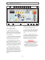
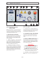
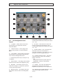
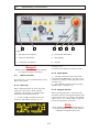
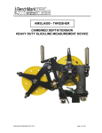
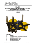
1
BAC
User Instruction
Manual
Document No. - 150BAC Global-000
MAKO Compressors, LLC
1634 SW 17th Street
Ocala, Florida 34471
Phone: +1-352-732-2268
Fax: +1-352-351-5211
E-mail: [email protected]
Web Site: www.compairmako.com/
CompAir UK Ltd.
Reavell House
53-56 - White House Rd.
Ipswich
Suffolk
IP15PB
England
Phone: 011-44-1473-242000
www.compair.com/Products/High_Pressure_Pistons-Breathing_Air_Compressors.aspx#Mako
e-mail: [email protected]
GENERAL INFORMATION.
These units are for compressing and purifying atmospheric air for use in Self Contained
Breathing Apparatus (SCBA) or Self Contained Underwater Breathing Apparatus (SCUBA) and
are not suitable for compressing any other gasses. They are designed and manufactured to
give optimum performance with long life and reliability.
This manual gives the end user all the information required to install and operate this unit and
carry out regularly scheduled maintenance to ensure the maximum satisfactory service life.
Servicing facilities and the supply of genuine MAKO replacement parts are provided through a
worldwide network of MAKO Distributors. If replacement parts are needed, the user should
first contact the local MAKO Distributor. If there is any difficulty contacting a local distributor
the end user may contact the MAKO factory representative.
The information given in this manual was correct at the time of it's creation. However, as part
of continuous development, modifications to parts and procedures may be made without
notice that could affect the maintenance requirements of this unit. Before any maintenance
work is undertaken the user is advised to contact the local MAKO Distributor who is supplied
with revised and up-dated information.
In any communication concerning these units it is essential to quote the MODEL, SERIAL
NUMBER and the YEAR of MANUFACTURE. This information is located on the units' nameplate.
(see Fig. 1.3-1)
Throughout this manual all pressures quoted are gauge pressures unless otherwise stated.
Manual Configuration
This manual is broken down by numbered chapters, sections and subsections shown in bold
text and separated by periods.
(Chapter #).(Section #).(subsection #).(subsection #)
4.3.2.1 would represent subsection 1 of subsection 2 of section 3 of chapter 4
There can be as many subsections as are needed.
Within this structure could be headings in bold which are not numbered.
The pages are designated by chapter and page separated by a dash.
(Chapter #)-(Page number within that chapter)
4-3 would indicate the third page of chapter four.
All illustrations are designated by chapter, section and subsection to which they are associated
followed by the number of the illustration separated by a dash
fig.(chapter and section designation)-(number of the illustration within the section
indicated)
fig. 4.3.2.1-3 would indicate the third illustration within section 4.3.2.1
0-1
Maintenance
To ensure the continued trouble-free operation of this unit it is important that periodic
maintenance and servicing is carried out in accordance with the information given in the
'Maintenance' section of this manual. To assist in this matter your local MAKO Distributor can
provide a number of optional maintenance agreements to suit your requirements. These
agreements provide the end user with the expertise of our factory trained technicians and the
guarantee that only Genuine MAKO parts will be used.
Warranty
The conditions of the MAKO Warranty are set out in the Company's standard Conditions of Sale
available from the MAKO Distributor supplying the unit.
USE ONLY GENUINE MAKO PARTS. YOUR
WARRANTY COULD BE AFFECTED IF ANY SERVICE
OR REPAIR IS CARRIED OUT USING ANYTHING
BUT GENUINE MAKO PARTS.
0-2
1.
1.1
Forward
in addition,
- relevant accident prevention regulations
- generally recognized safety regulations
- national safety regulations
have to be observed.
Notes On The Unit
MAKO units are the result of many years of
research and development. This experience
combined with high quality standards
guarantee the manufacture of breathing air
charging systems which will provide a long
service life, high reliability and costeffective operation.
This system must be operated under
technically perfect conditions and in
accordance with its intended use and the
instructions set out in the operating manual.
This system must be operated only by
safety-conscious personnel who are fully
aware of the dangers involved in the
operation of this system. If any functional
problem is detected or suspected stop the
operation of this system. Report the
problem to the appropriate maintenance or
service personnel. The problem must be
resolved before the system is returned to
operation.
Certificate Of Conformity
This unit and its accessories as supplied by
MAKO conform to the basic health and
safety requirements included in the
Machinery Directive 98/37/EC and the EMC
Directive 89/336/EEC. The compliance with
these directives is signified by the "CE
mark" (See fig. 1.1-1)
Operating the unit within the limits of its
intended use also involves observing the
instructions set out in the operating manual
and complying with the inspection and
maintenance directives.
1.3
Carefully performed maintenance is
imperative, this ensures that your unit can
meet all the requirements for which it was
intended. It is therefore imperative to
adhere to the specified maintenance
intervals and to carry out the maintenance
work with deliberate care, especially when
the unit is utilized under harsh operating
conditions.
fig. 1.1-1 CE
1.2
Intended Use
This unit has been constructed in
accordance with state-of-the-art technology
and recognized safety regulations.
Nevertheless, its use may constitute a risk
to life and limb of the user or third persons
or cause damage to the machine or to other
material property, if
-
Maintenance
Servicing
Please contact your authorized MAKO
distributor in the case of malfunctions or
when spare parts are required. Our fully
trained personnel will ensure that all repairs
are carried out properly. Using only genuine
MAKO spare parts. Genuine MAKO spare
parts are manufactured utilizing state-ofthe-art technology, thus guaranteeing the
continued reliable performance of the unit.
it is not used as intended,
it is operated by unqualified personnel
it is improperly modified or changed
the safety regulations are not observed
Therefore, any person entrusted with the
operation, maintenance or repair of this unit
must read and follow all safety regulations
in this manual. If required, this has to be
acknowledged by signature.
1-1
1.
Forward
ModelNumber,Numerodumodele,Modellnummer,
NumeroModello,N°modelo
SerialNumber,Numerodeserie,Seriennummer,
Numerodimatricola,N°serie
DateofManufacture,Datedefabrication,
Produktionsdatum,
Datadifabbricazione,
Fechadefabricacion
www.compairmako.com
MakoCompressors,L.L.C.
1634SW17thST.
Ocala,FL.34471
Ph.(352)732-2268
Fx.(352)732-7873
www.compair.com
HP,ch,PS,CV
Workorder,Bondetravail,
Arbeitsauftag,
Pedido,
Ordinedilavoro
V
KW
~
Hz
A
Diagramnumber,Nomrbredenimber,Diagramm-Zahl,
Numerodelloschema,Numerodeldiagrama
MotorRPM
Moteurr/min
MotorU/min
Motoregiri/min
CompressorRPM,Compresseurr/min,
KompressorU/min,
Compressoregiri/min,
CompresorRPM
Pressure
Pression
Druck
Pressione
Presion
CFM
pi3/min
cfm
ChargingRate
RegimedeCharge
BAR Ladegeschwindigkeit
bar Velocitadicarica
Bar Capacidaddecarga
PSI
CartridgeNumber
Numerodecartouche
Einsatz-Nummer
Numerocartuccia
N°cartucho
PurificationPN
ReinigungTN
Purificazionepn
PurificacionPN
M³/Hr
m3/h
1.
2.
3.
Compressor Model Number____________________________
Compressor Serial Number:____________________________
Date of Manufacturer:____________ Work Order:_________
HP:________ KW_________ FLA:________
Phase:____________
1634SW17thST.
Ocala,FL.43374
Ph.(352)732-2268
Fx.(352)351-5211
Voltage:(VAC)__________ Motor RPM:___________ Hz:___
SCCR: ______ AMPS Diagram Number:______________
Pressure: ___________PSI ____________BAR
Charging Rate: ___________CFM ______________M3/Hr
www.compairmako.com Compressor RPM:__________
Purification PN:_____________ Cartridge1 PN:___________
Cartridge2 PN:_____________ Cartridge3 PN:___________
fig. 1.3-1
MAKO Nameplates
In Case Of Queries
Observing these instructions will help to
avoid risks, reduce repair costs, down times
and to increase the reliability and service
life of the unit.
Please enter the data on the nameplate of
your unit into the nameplate shown in (fig.
1.3-1). In the case of queries or spare parts
orders, please refer to the units series &
type as indicated on the nameplate, the
identification no. and the year of
construction.
1.4
The operating instructions in this manual
are in addition to any applicable local,
regional or national, laws, rules and
regulations regarding the prevention of
accidents and environmental protection.
They must always be available at the
location of the unit. The operating
instructions must be read and followed by
any person carrying out work in connection
with the unit, i.e. operation, setting up,
disposal of any waste and consumables,
maintenance, inspection, repair, and
transport.
Notes
General
These operating instructions are intended to
familiarize the user with the unit and its
intended use. The instructions contain
important notes on how to operate the unit
safely and cost-effectively.
1-2
1.
Forward
Guarantee
Operate this unit only if you have an exact
knowledge of the machine taking into
respect these facts.
MAKO cannot be held responsible for the
safe operation of the unit if it is used in a
manner that does not correspond to the
intended use, or for other applications which
are not mentioned in this manual.
Warranty claims will not be accepted in the
case of
- Operating errors
- Incorrect maintenance
- Wrong auxiliary materials
- Use of spare parts other than genuine
MAKO spare parts
- Modifications and changes to the
installation
The warranty and liability conditions of the
general terms and conditions of MAKO will
not be extended by the notes above.
Any unauthorized change to this unit, or the
installation of components not accepted by
the manufacturer (i.e. fine separator) will
result in the withdrawal of the CE mark. As
a consequence, any liability and warranty
claims will not be accepted by the
manufacturer.
Safety Regulations
Danger!
The safety regulations in chapter 3 of the
operating instructions must be strictly
observed.
Technical Changes
In the course of technical development we
reserve the right to modify the units without
further notice.
1-3
2.
Table of Contents
General Information
Manual Configuration
Maintenance
Warranty
Declaration Of Conformity
0-1
0-1
0-2
0-2
0-3
1.
Forward
1.1 Notes On The Unit
Certificate Of Conformity
1.2 Intended Use
1.3 Maintenance
Servicing
In Case Of Queries
1.4 Notes
General
Guarantee
Safety Regulations
Technical Changes
1-1
1-1
1-1
1-1
1-1
1-1
1-2
1-2
1-2
1-3
1-3
1-3
2.
Table Of Contents
2-1
3.
Safety Regulations
3.1 Identification Of Safety Guidelines
3.2 General Safety Instructions
Organizational Measures
Selection And Qualification Of Personnel; Basic Responsibilities
3.3 Changes And Modifications To The Unit
3.4 Installation And Normal Operation
Condensate Drain
Normal Operation
3.5 Special Work / Maintenance
Lock Out Procedure
Maintenance And Repair
3.6 Warning Of Special Dangers
Electric Energy
Gas, Dust, Steam And Smoke
Pneumatics
Noise
Oils, Greases And Other Chemical Substances
Rooms Subject To Explosion Hazards
3.7 Storage Of Compressors
3.8 Symbols And Explanations
3.9 Logs And Daily Inspection
3.9.1 Daily Log Book
Out Of Service
Daily Inspection And Log Entries
3.9.2 Maintenance Log
2-1
3-1
3-1
3-1
3-1
3-2
3-2
3-2
3-3
3-3
3-4
3-4
3-5
3-6
3-6
3-7
3-7
3-7
3-8
3-8
3-8
3-9
3-12
3-12
3-12
3-12
3-13
2.
Table of Contents
4-1
4-1
4-2
4-3
4-3
4-6
4-8
4-10
4-11
4-12
4.
Layout And Function
4.1 General Description
4.2 Layout
4.3 Control Panels
4.3.1 MEC Controller
4.3.2 Standard Controls & Optional CMM
4.4 Air Management Panel Layout
4.5 Main Electrical Access
4.6 Front Access
4.7 Main Service Access Door
5.
Transportation And Installation
5.1 Transport
5.2 Machine Location
5.3 Power Supply
Lock Out Procedure
5.4 Reservoir Drain
5.5 Remote Air Intake Installation
5.5.1 Permanent Remote Air Intake
5.5.2 Temporary Remote Air Intake
5.6 Initial Startup Procedure
5-1
5-1
5-1
5-2
5-2
5-2
5-2
5-2
5-5
5-6
6.
Operating Instructions
6.1 MEC Controller
6.1.1 Start-Up
6.1.2 Shut-Down
6.1.3 Keypad Access
6.1.4 Modifying Set Points
Setting Air Pressure
6.1.5 Maintenance Menu
6.1.6 Service Functions
6.1.6.1 Purge
6.1.6.2 Keypad Re-Code
6.1.6.3 Calibrating CO Monitor
6.1.6.4 By-Passing The CO or MO Monitors
6.1.6.5 To Cancel The CO or MO By-Pass
6.2 Standard Controls
6.2.1 Start-Up
6.2.2 Shut-Down
6.3 CMM Unit
6.3.1 Keypad Commands
6.3.2 Menu Access
6.3.3 CO Setup
6.3.3.1 CO Set Point
6.3.3.2 Cal Interval
6.3.3.3 Automatic Cal
6.3.4 Calibrate Now
6.3.5 By-Pass CO or MO Monitors
6-1
6-1
6-1
6-1
6-1
6-2
6-2
6-2
6-3
6-3
6-3
6-3
6-4
6-4
6-5
6-5
6-5
6-6
6-6
6-6
6-6
6-6
6-7
6-7
6-7
6-8
2-2
2.
Table of Contents
6.3
6.4
7.
CMM Unit (continued)
6.3.5.1 To Cancel The CO or MO By-Pass
Standard Fill Procedure
6.4.1 Filling from Compressor
6.4.2 Cascade filling From Storage
Maintenance
Lock Out Procedure
7.1 Maintenance Schedule
Daily or Each Time Unit is Operated
Weekly
7.2 Purification System Layout & Function
7.3 Filter Cartridge Capacity & Replacement
Capacity
Replacement
7.4 CO Monitor Indicator (Window Type) Maintenance
7.5 Lubrication
7.6 Block Details
Appendices
MAKO Purification System Data Sheet for U.S. MK Models
MAKO Purification System Data Sheet for FD Models
Daily Log Book Sheet
Maintenance Log
Recommended Breathing Air Unit
Maintenance Schedule
Recommended Breathing Air Unit
Block Maintenance Schedule
Engineering Drawings / System Configuration Test Sheet &
Registration Form / Start-up & Inspection Form
2-3
6-8
6-9
6-9
6-10
7-1
7-1
7-1
7-1
7-1
7-2
7-2
7-2
7-2
7-4
7-4
7-5
APP-A
APP-B
APP-C
APP-D
APP-E
APP-F
3.
3.1
Safety regulations
Instructions, including supervisory
responsibility and duty of notification for
taking into account in-plant factors, for
example regarding work organization,
sequences of operations, personnel
assigned to certain tasks, are to be kept
with the operating manual.
Identification Of Safety
Guidelines
MAKO is not liable for any damage or injury
resulting from the non-observance of these
safety instructions or negligence of the
usual care and attention required during
installation, handling, operation,
maintenance or repair, even if this is not
explicitly mentioned in these operating
instructions.
The personnel entrusted with the operation
and/or maintenance of the unit must have
read the operating instructions and in
particular the chapter on safety regulations
before starting work. Reading the
instructions after work has begun is too
late. This applies especially to persons
working only occasionally on the machine,
e.g. for setting up or maintenance.
If any of the regulations contained in these
instructions - especially with regard to
safety - does not correspond to the local
legal provisions, the stricter of both shall
prevail.
supervisors should check on a regular basis
that the personnel are carrying out the work
in compliance with the operating
instructions and that they are paying
attention to the safety requirements!
Danger!
Passages marked with this designation
indicate a possible danger to personnel.
Important!
Passages marked with this designation
indicate possible damage to unit.
Observe all safety and warning notices
attached to the unit!
Note.
See to it that safety instructions and
warnings attached to the machine are
always complete and perfectly legible.
Passages marked with this designation
provide technical or procedural information
for the optimal cost-effective use of the
unit.
3.2
In the case of safety-relevant changes to
the unit or its operating behavior, stop the
unit immediately and report the fault to the
responsible department or person!
General Safety Instructions
Spare parts have to comply with the
technical requirements specified by the
manufacturer. This can always be ensured
by using only genuine MAKO spare parts.
Organizational Measures
The operating instructions must always be
at hand at the place of operation of the unit!
High pressure hoses have to be changed
within stipulated and periodic intervals,
even if no safety-relevant faults have been
detected.
In addition to the operating instructions, all
other generally applicable legal and other
mandatory regulations relevant to accident
prevention and environmental protection
must be adhered to and passed on to
others! These compulsory regulations may
also deal with the handling of hazardous
materials or the issuing/wearing of personal
protective equipment, or traffic regulations.
Adhere to prescribed intervals or those
specified in the operating instructions for
routine checks and inspections!
3-1
3.
Safety regulations
For the execution of maintenance work,
tools and workshop equipment adapted to
the task at hand are absolutely necessary.
Unauthorized changes to the machine are
not permitted for safety reasons.
Genuine MAKO parts were especially
designed and selected for this unit. The
installation and/or use of any parts other
than genuine MAKO parts can therefore
affect the active and/or passive safety and
reliability of this unit.
The personnel must be made familiar with
the location and operation of fire
extinguishers! Observe all fire-warning and
fire-fighting procedures!
Selection And Qualification Of
Personnel; Basic Responsibilities
The manufacturer is not liable for damage
resulting from the use of non-genuine MAKO
parts or special accessories. This applies
also to the installation and setting of safety
equipment and valves as well as to welding
on structural or pressurized parts.
Work on or with the unit must be carried
out by reliable personnel only. Statutory
minimum age limits must be observed!
Employ only trained or instructed personnel
and clearly set out the individual limits and
responsibilities of the personnel for
operation, set-up, maintenance and repair!
3.4
In addition to the general technical
operation in accordance with the
stipulations of the local authorities, we
would like to refer in particular to the
following regulations.
Ensure that only authorized personnel work
on or with the unit!
Define the machine operator's
responsibilities giving the operator the
authority to refuse instructions by third
persons that are contrary to safety
regulations.
For the lifting of this unit, a suitable lifting
mechanism is to be used, which meets the
local safety regulations. All loose or
moveable parts must be safely secured
before the unit can be lifted. It is strictly
prohibited to stay in the danger zone of a
lifted load.
Do not allow persons to be trained or
instructed or persons taking part in a
general training course to work on or with
the unit without being continuously
supervised by an experienced person!
The correct method of lifting (according to
the operating instructions of the load
suspension device) has to be ensured.
Work on the electrical equipment of the unit
must be carried out only by a skilled
electrician in accordance with electrical
engineering rules and regulations.
All blind flanges, plugs, caps and bags with
drying agent have to be removed prior to
the installation of the pipes. Distributing
pipes and pipe connections have to be of
the proper size and suitable for the relevant
operating pressure.
Work on system elements such as high
pressure hoses may only be carried out by
personnel with special knowledge and
experience.
3.3
Installation And Normal
Operation
The system has to be installed in such a
way that it is adequately accessible and the
required cooling is guaranteed. Never block
the air intake. Make sure that the ingress of
humidity via the intake air is kept to a
minimum.
Changes And Modifications
To The Unit
Do not make any changes, modifications or
attachments to the unit, which could affect
safety, without the supplier's prior
permission!
3-2
3.
Safety regulations
Check regularly that
The air intake is to be located so that no
hazardous Contaminant can be drawn in.
(i.e. solvent vapor, dusts and hazardous
material and flying sparks)
- all means of protection are correctly fitted
and fixed.
- all hoses and/or pipes within the system
are in good condition, firmly fixed and do
not chafe.
- there are no leaks (air, oil, fuel, or
coolant).
- all fittings are firmly tightened.
- all wires are connected correctly and are
in good condition.
- all safety valves and other pressure relief
mechanisms are in good order and not
blocked by e.g. dirt or paint.
- the safety mechanisms are fully
functional.
The air intake is to be positioned so that no
loose clothing of persons can be sucked in.
The pressure line connected to the air outlet
of the system must be fitted stress-free.
If a remote control is used, the system
must carry a clearly visible sign with the
following note:
Attention! This installation is operated by
remote control and can start up without
prior warning!
If compressed air hoses are used. they
must be of the proper size and suitable for
the relevant operating pressure. Do not use
chafed or damaged hoses.
As an additional safety measure, persons,
who start remotely controlled systems, have
to take sufficient safety precautions in order
to ensure that nobody is checking the
system or working on it. For this, a label
with a corresponding warning notice has to
be attached to the remote control
equipment.
Only use hose couplings and fittings of the
right type and the correct size.
Before blowing through a hose or an air
pipe ensure that the open end is positively
held. A free end whips and can cause
injuries.
The installed unit-specific safety valves only
assume the pressure safeguarding function
of this unit provided in currently valid
standards and regulations.
Before loosening or disconnecting any
connection ensure that it in not under
pressure.
Electrical connections must meet the local
regulations. Power units must be connected
to earth and protected from short-circuits
by means of fuses.
Refrain from any working method which is
doubtful in terms of safety.
Condensate Drain
Never play around with compressed air from
this unit!
The condensate discharge is to be disposed
of in accordance with all applicable local
laws, rules and regulations
Never aim compressed air from this unit at
yourself or at any other person!
Normal Operation
Never use compressed air from this unit to
clean your clothing.
The system pressure of the unit can be
located on the nameplate of the unit.
Never use compressed air from this unit to
clean equipment.
Take the necessary precautions to ensure
that the unit is used only when in a safe and
reliable state!
Never use the machine in an environment
where inflammable or poisonous vapour can
be sucked in.
Operate the machine only when all
protective equipment, emergency shut-off
equipment, sound-proofing elements and
extraction devices are in place and fully
functional!
3-3
3.
Safety regulations
Follow the adjusting, maintenance and
inspection activities and schedule set out in
the operating instructions, including
information on the replacement of parts and
equipment. These activities must only be
carried out by skilled personnel, under
qualified supervision.
Never operate the system at pressures and
temperatures below or above the values
indicated in the technical data sheet.
All access panels, etc. have to be closed at
all times during the operation of this unit.
Persons in an environment or areas in which
the sound pressure is 85 dB(A) or higher
have to wear ear protectors.
Brief the personnel operating the unit prior
to starting any special operations or
maintenance work! Appoint a person to
supervise the activities!
Check the unit at the beginning of each
startup and at least once every 8 hours of
operation for visible damage or problems.
Report any problems or changes in the
machine's operating Behavior to the
responsible department or person
immediately. In the case of any problem
which might effect the safe operation of this
unit, stop the unit immediately! Have any
problem resolved before restarting the unit!
Maintenance and repair work may only be
carried out under the supervision of a
person who is qualified to do the work.
Oil losses result in a slippery floor.
Therefore, always clean the floor and the
outside of the unit prior to starting any
maintenance work.
Inspection, maintenance and repair work
may only be carried out with the unit being
at rest and depressurized. Protective
equipment to be removed for this work has
to be properly refitted after completion of
these activities.
Follow the start-up and shut-down
procedures according to the operating
instructions.
3.5
Special Work/Maintenance
During installation, inspections,
maintenance, or repairs the following lockout procedure must be followed:
The use of this unit without protective
equipment is not permitted. During
maintenance and repair when working on a
running unit, working clothes have to be
close-fitting.
Lock Out Procedure:
1. - Announce the lock-out to other
personnel.
2. - Turn off site power box to the unit.
3. - Lock site power box to the unit in the
off position and place warning tag on box.
4. - Put key in your pocket.
5. - Make sure unit is clear of all personnel.
6. - Test lock-out by trying to start the unit.
7. - Complete required operations.
8. - Announce that the lock-out condition is
being ended and clear the unit of all
personnel.
9. - Take key out of your pocket.
10. - Unlock the power box and remove
warning tag from box.
11. - Turn the power box on.
12. - Announce that the unit has power to
other personnel.
Always use the correct tools for
maintenance and repair work.
Never use inflammable solvents or carbon
tetrachloride to clean parts. Take
precautions against poisonous vapors from
cleaning agents.
In any work concerning the operation,
conversion or adjustment of the unit and its
safety-oriented devices or any work related
to maintenance, inspection and repair,
always observe the start-up and shutdown
procedures set out in the operating
instructions and the information on
maintenance work.
Ensure that the maintenance area is
adequately secured.
3-4
3.
Safety regulations
To lower the risk of accidents, individual
parts and large assemblies being moved for
replacement purposes should be carefully
attached to lifting tackle and secured. Use
only suitable and technically correct lifting
gear and only utilize suspension systems
with adequate lifting capacity. Never work
or stand under suspended loads!
Never weld any pressure reservoir or
change it in any way.
During maintenance and when carrying out
repair work, cleanliness is very important.
Avoid the ingress of dirt by covering parts
and free openings with a clean cloth, paper
or adhesive tape.
Before releasing this unit for operation after
maintenance or overhaul check that the unit
is functioning properly and the regulating,
shut-down equipment and safety interlocks
are working properly.
After the completion of each repair, check
that no tooling, loose parts, cloth or debris
have been left in the unit.
Examine the pressure tube and the pressure
vibration dampers for carbon deposits every
six months. Excessive deposits have to be
removed.
If work which produces heat, flames or
sparks has to be carried out on or near this
unit, the adjacent components of this unit
have to be protected by means of non
inflammable material.
Care must be taken any time this unit is in
operation!
Motor, air filter, electrical components and
regulating equipment have to protected
from the ingress of humidity, e.g. when
cleaning the system by means of a steam
jet.
Maintenance And Repair
The employer has to inform the employee of
the dangers possibly arising during the
repair and maintenance of this unit as well
as on how to avoid them; the employee has
to observe all measures for safety at work.
Safety equipment for the prevention or
elimination of danger has to be maintained
regularly and functionally checked at least
once a year. Faults observed have to be
immediately rectified and/or reported to the
responsible person.
Under no circumstance shall the soundproofing material be removed or modified.
Never use etching solvents which could
attack the materials used.
If indicated or if there is any suspicion that
an internal part of the unit has run hot, the
machine has to be shut down and the unit
checked.
Use only genuine MAKO spare parts.
In order to avoid an increase in the
operating temperature, check and clean the
heat transfer surfaces (cooling fins,
intermediate cooler, etc.) at regular
intervals. Prepare a plan of the most
favorable cleaning intervals for this unit.
During installation, inspections,
maintenance, or repairs the lock-out
procedure must be followed. (see section
3.5)
Before removing or opening pressurized
components, positively isolate any source of
pressure and depressurize the entire
system.
Avoid damage to the safety valves and
other pressure reducing components. Check
in particular for clogging caused by paint, oil
carbon or the accumulation of dust, which
could deteriorate the effectiveness of these
components.
Never weld or carry out any other work
requiring heat near oil systems. Pressure
reservoirs or components and pipes
containing oil have to be drained completely
and cleaned, for example by means of a
steam jet, before beginning such work.
3-5
3.
Safety regulations
for safety and/or functional reasons, in
particular electric motors and switch
cabinets.
Insulation or protective shielding, the
temperature of which may exceed 70°C and
which could be erroneously touched by the
personnel, must not be removed before
these parts have cooled down to room
temperature.
After cleaning, remove all covers and
masking completely and allow the unit to
dry before returning unit to service!
Check the accuracy of pressure and
temperature indicators at regular intervals.
If the admissible tolerance limits have been
exceeded, these devices must to be
replaced.
Always re-tighten screwed connections
which have been loosened for maintenance
and repair work.
If the set-up, maintenance or repairs
require the removal of safety equipment,
this equipment has to be replaced and
checked immediately after these activities.
Before removing or overhauling a
compressor, a motor or any another
equipment, ensure that all moveable parts
are safely secured. After completion of
repair work, always verify that no tools,
loose parts or cloths have been left in or on
the unit, drive motor or drive equipment.
Units must be cycled several times in order
to ensure that there are no mechanical
faults in the machine or the drive members.
Check the direction of rotation of the
electric motors during first commissioning
and after each modification of the electrical
connections in order to prevent the
compressor from being damaged.
Ensure that consumables and replacement
parts are disposed of in a safe and
environmentally friendly manner in
accordance with all applicable local, regional
and national laws, rules and regulations.
3.6
Warning Of Special Dangers
Electric energy
Use only genuine MAKO fuses with the
specified current rating. Switch off the
machine/unit immediately if trouble occurs
in the electric system.
The fastening of loads and the instructing of
forklift or crane operators should be
entrusted to experienced personnel only.
The person giving the instructions must be
within sight or voice contact with the
operator.
Work on the electrical system or equipment
must only be carried out by a skilled
electrician or by specially instructed
personnel under the control and supervision
of such an electrician and in line with the
relevant electrical engineering rules.
For carrying out overhead assembly work
always use specially designed or otherwise
safety-orientated ladders and working
platforms. Never use machine parts as a
climbing aid. Wear a safety harness when
carrying out maintenance work at greater
heights.
If regulations require, the power supply to
parts of machines and plants on which
inspection, maintenance and repair work is
to be carried out must be cut off. Before
starting any work, check the de-energized
parts for the presence of power and ground
or short-circuit them in addition to
insulating adjacent live parts and elements.
Clean the machine, especially connections
and threaded unions, of any traces of oil,
fuel or preservatives before carrying out
maintenance or repair work! Never use
aggressive detergents! Use lint-free
cleaning rags!
The electrical equipment of this unit is to be
inspected and checked at regular intervals.
Defects such as loose connections or
scorched cables must be rectified
immediately.
Before cleaning the machine with water or
steam jet (high pressure cleaner) or other
cleaning agents, initiate an electrical lockout procedure(see section 3.5), cover all
openings which have to be protected from
the ingress of water, steam or detergents
3-6
3.
Safety regulations
Compressed-air lines must be laid and fitted
properly. Ensure that no connections are
exchanged. The fittings, lengths and quality
of hoses must comply with the technical
requirements.
Necessary work on live parts and elements
must be carried out in the presence of a
second person who can cut off the power
supply in case of danger by operating the
emergency shutdown or main power switch.
Secure the working area with a red-andwhite safety chain and a warning sign. Use
insulated tools only.
Noise
Sound-proofing elements on the unit have
to be active during operation. See section
4.1 for the noise levels of this unit.
Wear personal ear protection as prescribed.
Before starting work on high-voltage
assemblies and after having cut out the
power supply, the feeder cable must be
grounded, and components, such as
capacitors, short-circuited with a grounding
rod.
Noise, even at a low level, can cause
nervousness and annoyance; over a longer
period of time, our nervous system can
suffer serious damage. We therefore
recommend a separate machine room in
order to keep the noise of the machine
away from the workshop.
Gas, Dust, Steam And Smoke
Carry out welding, flame-cutting and
grinding work on the machine/unit only if
this has been expressly authorized, as there
may be a risk of explosion and fire.
Depending on the number of machines in a
machine room, the noise can be quite loud.
In accordance with the sound pressure level
at manned posts, the following precautions
have to be taken:
Before carrying out welding, flame-cutting
and grinding operations, clean the
machine/unit and its surroundings from
dust and other inflammable substances and
make sure that the premises are adequately
ventilated (risk of explosion)!
- Below 70 dB(A): no special measures
- Above 70 dB(A): persons who stay
permanently in this room have to wear ear
protectors
Adhere to the regulations valid for the place
of operation!
- Below 85 dB(A): in the case of occasional
visitors who stay in this room only for a
short while, no special precautions are to be
taken
Observe any existing national regulation if
work is to be carried out in small rooms.
Pneumatics
- Above 85 dB(A): hazardous noise zone! A
warning sign has to be attached to each
entrance indicating that everybody who
enters the room, even for a short time only,
has to wear ear protectors.
Work on high pressure air equipment must
only be carried out by persons with special
knowledge and experience of high pressure
air systems.
Check all lines, hoses and threaded
connections regularly for leaks and obvious
damage. Damage must be Repaired
immediately. High pressure air may cause
serious injury or death.
- Above 95 dB(A): the warning signs have
to contain the recommendation that
occasional visitors also have to wear ear
protectors.
Depressurize all system sections, pressure
pipes, tubing and hoses which are to be
removed in accordance with the specific
instructions for the assemblies concerned
before carrying out any repair work.
- Above 105 dB(A): special ear protectors,
which are suitable for the noise level and
the spectral composition of the noise must
be available. A corresponding warning sign
must be fixed to each entrance door.
3-7
3.
Safety regulations
Units which have been commissioned must
be run continuously for a minimum of 1
hour once a week.
Take care that the noise transmission
through walls and frames does not result in
too high a noise level in the surrounding
areas.
Units which are not run continuously for a
minimum of 1 hour once a week require
additional precautions to be taken by
qualified service personnel.
Oils, Greases And Other Chemical
Substances
When handling oils, greases and other
chemical substances, observe the safety
regulations for this product!
Note.
The following conditions must be taken into
account for storage of this unit.
Be careful when handling hot fuels and
consumables (danger of burning or
scalding)!
The unit should be stored in a dry building
which should be heated if possible.
Rooms Subject To Explosion Hazards
This is particularly true during the months
of winter.
Danger !
If there is a risk that the temperature will
fall or rise above the limits of -10C to +65C
(14F to 149F) , the electrical controller must
be removed and stored in ambient
temperatures of+5C to +30C (41F to 86F).
Units must never be operated in areas
subject to explosion hazards!
(Exception: Special units with the
corresponding technical modifications)
3.7
Before commissioning the compressor all
the electrical and electronic components
and units should be checked for the ingress
of water or condensation.
Storage Of Compressors
All units are protected against corrosion at
the factory for transport and for brief
storage before commissioning.
If the units are to be stored for period
exceeding six months before
commissioning, additional precautions must
be taken by qualified service personnel.
3-8
3.
3.8
Safety regulations
Symbols And Explanations
The Following Symbols may be used on the
unit.
fig. 3.8-4
Warning, Electrical Shock or Electrocution
fig. 3.8-1
Warning, Fan, Cutting Danger
fig. 3.8-5
Warning, Pressurized Bottle
fig. 3.8-2
No Access for Unauthorized Personnel
fig. 3.8-6
Warning, Hot Surface
fig. 3.8-3
Warning, Automatic Start-Up, May Start
Without Warning.
3-9
3.
Safety regulations
fig. 3.8-7
Read Operators Manual before continuing
fig. 3.8-10
Drain
fig. 3.8-8
Read Technical Manual before continuing
fig. 3.8-11
Forklift, Left Most Lift Point
fig. 3.8-9
Warning! See the User Instruction Manual
for specific hazzards associated with this
unit.
See the section of the users manual
associated with this area of this unit for
specific hazzards associated with this area.
fig. 3.8-12
Forklift, Right Most Lift Point
3-10
3.
Safety regulations
fig. 3.8-13
Warning, Hand Entanglement, Belt Drive
fig. 3.8-16
Lock-Out Procedure Required
fig. 3.8-14
Warning, Release of Pressure
fig. 3.8-17
Hearing Protection Required
fig. 3.8-15
Warning, Skin Puncture Danger
fig. 3.8-18
Eye Protection Required
3-11
3.
Safety regulations
Daily Inspection & log Entries
1. - Check that no one has taken the unit
out of service.
2. - After the unit is determined to be in
service, Do not start the unit, enter the
date in the daily log and begin your
inspections.
3. - Check the oil level of the compressor
and engine. If oil is milky take unit out of
service and report this to service personnel.
fig. 3.8-19
Check Oil Level before each Start-Up
3.9
Logs And Daily Inspections
MAKO Supplies two log sheets. The first is a
daily log sheet, appendix-D, used by
Operator. Make additional copies and create
a daily log book. The second is a
maintenance log sheet maintained by the
service personnel. Keep both logs with the
unit at all times.
3.9.1 Daily Log Book
The daily log book should be checked each
and every time before the unit is turned on.
Out of service
After any shut down or perceived problem
unit must be taken out of service and “Out
Of Service” must be written in daily log.
Do not try and restart unit until problem is
resolved.
Report any such shut-down or problem to
appropriate service personnel.
After problem is solved unit is put back in
service, the solution is documented,
initialed and dated in the daily log.
Check Oil levels regularly during continuous
use.
Top off oil levels as necessary.
The compressor can not use the same oil as
the engine.
Use only Genuine MAKO Compressor oil in
the compressor. (see section 7.5)
Oil for the engine is per engine
manufacturers recommendations.
Check for oil leaks and walk around unit and
look for problems.
Check Auto Drain Reservoir and empty as
necessary.
If any problems are found that could effect
the safe operation of the unit take the unit
out of service and report to service
personnel.
Document any actions taken in daily log.
After unit has been approved for service
place check in “Oil Level-Leaks” column and
continue.
3-12
3.
Safety regulations
4. - Check the ambient air quality at the air
intake and surrounding area. If the air
quality is not acceptable take the unit out of
service. If the air quality is acceptable place
a check mark in the “Ambient Air Quality”
column and continue.
5. - Record the hours reading on the unit.
MEC Controller: it will be necessary to press
the main on / off button (#2 on fig. 6.1-1)
to view the hours run off the MEC display.
Compare hours run on unit and current date
against the “Maintenance Log” and against
the due hour and date of the next filter
change and oil change (see section 7.3 for
information on filter changes and section
7.5 for information on oil changes)
Note overdue maintenance, filter change or
oil change and take the unit out of service.
Report the overdue service to service
personnel.
Report maintenance, filter change or oil
change coming due to service personnel.
7. - Place Your initials in the operator
column.
8. - Unit can now be started.
9. - Listen and look for air leaks. If an air
leak is detected take the unit out of service.
Report leak to the service personnel.
Danger!
High pressure air leaks can be very
dangerous.
Document any actions, alarms, concerns or
observations in the “Alarms and Comments”
column. (i.e. topped off compressor oil.)
When the unit is shut down record the
hours reading in the “Hours Start/Stop”
column.
3.9.2 Maintenance Log
The maintenance log is intended to be filled
out and signed by the maintenance and
service personnel When the service is
completed.
After it has been determined that no
maintenance, filter change or oil change are
overdue place a check in the
“Maintenance/Filter” column and continue.
6. - Close all access doors. All access panels
must be in place.
3-13
4.
Layout and function
3. - The regulation and control of high
pressure breathing air from storage or
directly from the compressor system to
preclude SCBA / SCUBA over pressurization.
fig. 4.1-1
4.1
General Description
The Mako Breathing Air Center “BAC” (See
Fig. 4.1-1) incorporates all functions
required to safely supply high pressure
breathing air that meets or exceeds CGA
Grade E criteria. These functions include:
4. - The flexibility to control multiple banks
of storage to allow the efficient filling of
bottles through the use of a cascade filling
procedure.
5. - The ability to monitor and control the
filling of mobile storage units.
1. - Delivery of high pressure air to the
purification subsystem at a temperature
only slightly above the ambient air
temperature (Max. Ambient air temperature
113°F or 45°C) (approximately 18°F or
10°C above ambient)
6. - The strength to protect personnel in the
event of a catastrophic failure of a SCBA /
SCUBA tank in the process of being filled in
the containment station.
Air leaving the last stage separator contains
some compressor oil carryover and
moisture. Moisture content is a function of
pressure and air temperature at the last
stage separator.
Danger!
Do not use system for any application other
than for breathing air system
2. - Reduction of the moisture content and
impurity levels in the air stream issuing
from the last stage separator to CGA Grade
"E" criteria by adsorption, chemical
reaction, and filtration in the purification
subsystem.
4-1
4.
Layout and function
2
1
3
4
7
5
6
7. - Main Service Access Door - (see section
4.7)
fig. 4.2-1 Overall View
4.2
Layout
1
1. - Control Panel - Standard Controller with
optional CMM System is shown. (see section
4.3.1 for MEC controller or section 4.3.2 for
standard controls and optional CMM)
2
2. - Air Management Panel - 4 bank cascade
with single regulator shown (see section
4.4)
3. - Fill Hose - each fill Hose consists of a
flexible high pressure hose with a standard
bottle connection a shutoff valve and a
bleed valve. (see fig. 4.2-2)
3
fig. 4.2-2 Fill Whip
4. - Containment Fill Station Access Handle
- With door closed push handle down to
open fill station. With door open pull handle
up to close fill station.
1. - Fill Hose Valve - These valves will make
it possible to use individual fill hoses.
2. - Fill Hose Bottle Connection - These
standard connections will correspond to the
style and pressure rating of the bottle it is
designed to fill.
5. - Main Electrical Access Door - To be
accessed by authorised service personnel
only (see section 4.5)
6. - Front Access Door - (see section 4.6)
3. - Fill Hose Bleed Valve.
4-2
4.
Layout and function
17
18
9
12
8
7
6
5
11
14
15
10
fig. 4.3.1-1
4.3
13
1
16
3
4
2
5. - Oil Pressure Low - (RED) indicates oil
pressure was low for more than 30 seconds.
Compressor Will Shut Down. Take the unit
out of service. (see section 3.9.1)
Control Panels
4.3.1 MEC Controller
6. - Air Temperature High - (RED) Indicates
air temperature is to high for safe operation
of the unit. Compressor Will Shut Down.
Take the unit out of service. (see section
3.9.1)
1. - Emergency Stop - Pushing the
emergency stop button will instantly
disconnect the power from the compressor
and all electronics. Turn emergency stop
button clockwise to reset, before the unit
can be restarted.
7. - High Air - (GREEN) Indicates the air
pressure has reached the high set point and
has shut down. The light will turn off and
the compressor will restart when the air
pressure at the outlet of the unit has
dropped to the low set point of the unit.
2. - MEC On / Off Button - Press this button
to turn on the MEC Controller this button
will light up green as long as the MEC is on.
Press this button again to turn off.
Important !
3. - Compressor On Button - Press this
button to enable the compressor, it will light
up green. Controller will start the
compressor. If the compressor shuts down
for any abnormal reason an alert message
will be shown on the display #17. Take the
unit out of service. (see section 3.9.1)
A “popping” relief valve is a indication of
excessive pressure in the system.
Shut off the compressor and contact your
authorized service personnel.
DO NOT set the relief valve to a higher
pressure as this will void the warranty and
may permanently damage the unit.
4. - Compressor Off Button - When this
button is pressed the MEC controller will
stop or not restart the compressor. It will
light up (RED) when pressed if the MEC
controller is turned on. If an alarm condition
exists this button will silence the alarm but
will not clear the alert message from the
display.
4-3
4.
Layout and function
8. - Inlet Filter Dirty - (RED) Indicates the
inlet air filter is dirty and it is time to clean
it or change it. The compressor will shut
down. Take the unit out of service. (see
section 3.9.1)
14. - Carbon Monoxide Level Monitor - This
is an optional feature and will operate like
this.
Green light = air is indicated to be within
established safe limits if the unit has been
properly calibrated.
Yellow Light = air is indicated to be safe but
is within 50% of the upper safe limit. This
condition should be looked into and the
condition corrected soon.
Red Light = air is indicated to be beyond
established safe limits. Compressor will shut
down and display an alarm message. Take
the unit out of service. (see section 3.9.1)
9. - Motor Overload - (RED) Indicates the
motor has experienced an overload. The
compressor will shut down. Take the unit
out of service. (see section 3.9.1)
10. - No Filter - (RED) Indicates there is no
filter in the purification chamber. Take the
unit out of service. (see section 3.9.1)
11. - Auto-Drain On - (GREEN) Indicates the
auto drain valve is activated. Valve should
close in approximately 7 seconds.
Danger!
Do not try to use this unit until this issue is
resolved.
12. - Condensate Reservoir Full - (RED)
Indicates that condensate reservoir is full
and it is time to drain the condensate and
oil from the condensate reservoir. The
compressor will shut down. The system can
not be reset or run until reservoir is
drained. Handle waste in accordance with all
local safety and environmental laws or
regulations.
15. - This display will show what monitoring
systems have been installed in this unit.
Off - display is not turned on = neither the
carbon monoxide nor the moisture monitors
have been installed.
CO is displayed = the electronic carbon
monoxide monitoring system has been
installed.
MS is displayed = the electronic moisture
monitoring system has been installed.
CM is displayed = both the electronic carbon
monoxide and the moisture monitoring
systems have been installed.
13. - Moisture Level Monitor - This is an
optional feature and will operate like this.
Green light = air is indicated to be within
established safe limits.
Yellow Light = air is indicated to be within
established safe limits but is within 10% of
the upper safe limit. There is approximately
1 hour of continuous use between yellow
warning and red shutdown.
Red Light = air is indicated to be beyond
established safe limits. Compressor will shut
down and display an alarm message. Take
the unit out of service. (see section 3.9.1)
If your unit does not have either one or
both of these systems and you would like to
have either or both of them added please
contact your local MAKO distributor for more
information.
Danger!
Do not try to use this unit until this issue is
resolved.
4-4
4.
Layout and function
16. - Calibration - (Blue)Indicates the unit is
in the process of calibrating the electronic
CO monitor. The unit may not be used until
the calibration process has been completed.
17. - Display - This display will provide
information, warnings and menu options
needed by the operator, maintenance and
service personnel.
The main Screen will show the pressure in
the purification chambers of the system it
will typically maintain 2400 psi (165 bar) for
the 06, 07, 08 & 09 blocks or 1900 psi (131
bar) for the 04, 05 & 05E blocks even when
the system is off, the block is depressurized
and system outlet is vented. This pressure
is maintained in the purification system to
preserve the purification medium. When the
pressure on the display is higher than the
maintained pressures shown above, the
pressure shown on the display will be the
same as the system outlet pressure.
18. - Keypad - This keypad will allow the
maintenance and service personnel to
collect data, navigate through menu options
and change settings.
4-5
4.
13
Layout and function
12
10
11
7
6
14
5
9
fig. 4.3.2-1
1
8
3
4
2
4. - Compressor Off Button - (RED) When
this button is pressed the compressor will
stop or not restart.
4.3.2 Standard Controls &
Optional CMM
5. - Oil Pressure Low - (RED) indicates oil
pressure was low for more than 30 seconds.
Compressor Will Shut Down. Take the unit
out of service. (see section 3.9.1)
Reference numbers 1 thru 9 are all part of
the standard controls. Reference numbers
10 thru 14 are all part of the optional CMM
(CO and Moisture Monitor) unit.
6. - Air Temperature High - (RED) Indicates
air temperature is to high for safe operation
of the unit. Compressor Will Shut Down.
Take the unit out of service. (see section
3.9.1)
1. - Emergency Stop - Pushing the
emergency stop button will instantly
disconnect the power from the compressor
and all electronics. Turn emergency stop
button clockwise to reset, before the unit
can be restarted.
7. - High Air - (GREEN) Indicates the air
pressure has reached the high set point and
the compressor has shut down. The light
will turn off and the compressor will restart
when the air pressure has dropped to the
low set point of the unit.
2. - CMM On / Off Button - Press this button
to turn on the CMM monitoring unit this
button will light up green as long as the
CMM unit is on. Press this button again to
turn off the CMM monitoring unit.
Important !
3. - Compressor On Button - Press this
button to start the compressor, it will light
up green. If the compressor shuts down for
any abnormal reason take the unit out of
service. (see section 3.9.1) Do not try to
restart the unit until the cause of the shut
down has been resolved.
A “popping” relief valve is a indication of
excessive pressure in the system.
Shut off the compressor and contact your
authorized service personnel.
DO NOT set the relief valve to a higher
pressure as this will void the warranty and
may permanently damage the unit.
8. - Hour Meter - The hour meter will record
the number of hours the compressor has
run.
4-6
4.
Layout and function
9. - Purification System Pressure Gauge This gauge will read the pressure in the
purification chambers of the system it will
typically maintain 2400 psi (165 bar) for the
06, 07, 08 & 09 blocks or 1900 psi (131
bar) for the 04, 05 & 05E blocks even when
the system is off, the block is depressurized
and system outlet is vented. This pressure
is maintained in the purification system to
preserve the purification medium. When the
pressure on the gauge is higher than the
maintained pressures shown above, the
pressure shown on the gauge will be the
same as the system outlet pressure.
12. - Carbon Monoxide Level Indicator This is a standard feature of the CMM unit
and will operate as follows.
Green light = air is indicated to be within
established safe limits if the unit has been
properly calibrated.
Yellow Light = air is indicated to be safe but
is within 50% of the upper safe limits. This
condition should be looked into and the
condition corrected soon.
Red Light = air is indicated to be beyond
established safe limits. Compressor will shut
down and display an alarm message. Take
the unit out of service. (see section 3.9.1)
If the CMM electronic carbon monoxide
monitoring system has not been installed on
your unit the carbon monoxide levels will
have to be monitored from a window type
carbon monoxide monitor which will be
mounted behind the front access panel and
above the main electrical enclosure (see
section 4.4 #5)
Danger!
Do not try to use this unit until this issue is
resolved.
13. - Calibrating - This light indicates the
unit is in the process of calibrating the
electronic CO monitor. The unit may not be
used until the calibration process has been
completed.
NOTE.
14. - Keypad - This keypad will allow the
maintenance and service personnel to
navigate through menu options and change
settings. (see section 6.3.1)
The CMM unit is optional. Reference
numbers 10 thru 14 are all part of the CMM
unit.
10. - Display - This display will provide
information, warnings and menu options
needed by the operator, maintenance and
service personnel.
NOTE.
If you do not have the CMM (CO and
Moisture Monitoring) unit and would like to
please contact your local MAKO distributor
for more information.
11. - Moisture Level Indicator - This is an
optional feature on the CMM unit and if
purchased and installed will operate as
follows.
Green light = air is indicated to be within
established safe limits.
Yellow Light = air is indicated to be safe but
is within 10% of the upper safe limits. This
condition should be looked into and the
condition corrected soon. There is
approximately 1 hour of continuous use
between yellow warning and red shutdown.
Red Light = air is indicated to be beyond
established safe limits. Compressor will shut
down and display an alarm message on the
display. Take the unit out of service. (see
section 3.9.1)
Danger!
Do not try to use this unit until this issue is
resolved.
4-7
4.
Layout and function
1
12
2
11
3
10
4
5
6
7
fig. 4.4-1 Air Management Panel
8
9
7. - Bottle Pressure - This Gauge will read
the pressure going to the bottle(s) in the
Containment Shield Box Drawer(see section
4.2 - #4).
4.4
Air Management Panel
Layout
8. - Fill Valve - This Valve will control the
flow of air going to the bottle(s) in the
Containment Shield Box Drawer(see section
4.2 - #4).
1. - * To Bank - These valves control the
flow between the compressor and the
individual Banks.
2. - * Bank Pressure - These gauges will
give you the pressure in each individual
Bank.
9. - Auxiliary Outlet - This connection will
allow this unit to be connected to a
secondary fill station or be used to fill other
storage or as a air sample test port.
3. - * From Bank - These valves control the
flow between the individual banks and the
rest of the Air Management Panel.
4. - Inlet Pressure - This Gauge will read the
pressure at the inlet of the Regulator [#5].
10. - Auxiliary Outlet Control - This valve
controls the flow of air to the Auxiliary
Outlet connection.
- Off
- Unregulated with full system pressure
- Regulated - pressure controlled by
Regulator [#5]
5. - Regulator - This devise can be set to
reduce the storage or compressor pressure
to the proper fill pressure.
11. - Bypass - This valve can Bypass all
storage and connect the inlet of the
Regulator [#5] directly to the compressor.
6. - Outlet Pressure - This Gauge will read
the pressure at the outlet of the Regulator
[#5].
12. - Window Type CO MO Indicator - View
Indicator through window.(see fig.
4.4-2)
* - Cascade fill panels may be setup for up
to 4 Banks.
4-8
4.
Layout and function
1
3
2
4
fig. 4.4-2 CO / MO Indicator
1. - MO Indicator Ring - (Blue) Safe
conditions.
2. - MO Indicator Ring - (Pink) Unsafe
conditions. Relative humidity greater
than 40%.
3. - CO Indicator Disk - (Yellow) Safe
conditions.
4. - CO Indicator Disk - (Brown/Black)
Unsafe conditions. CO content greater
than 50ppm.
(see section 7.4 for maintenance info.)
4-9
4.
Layout and function
3
4
2
1
fig. 4.5-1
4.5
Main Electrical Access
1. - Main Electrical Box - This box contains
high voltage electrical shock hazzard even if
the unit is turned off. Do Not Open to be
serviced by trained personnel only.
2. - Oil Pressure Switch - on 06 and larger
Compressor Blocks
3. - Air Pressure Switch
4. - Motor Compressor Belt Drive Assy.
4-10
4.
Layout and function
5
1
2
6
3
7
4
8
fig. 4.6-1
4.6
8. - Motor Compartment Located Below
Compressor Compartment.
Front Access
1. - Oil Pressure Gauge - On all BAC units
with 06 and larger compressor blocks.
2. - First Stage Pressure Gauge - shows the
pressure between the first stage and the
second stage of the compressor.
3. - Second Stage Pressure Gauge - shows
the pressure between the second stage and
the third stage of the compressor.
4. - Third Stage Pressure Gauge - only on 4
stage compressors. shows the pressure
between the third stage and the forth stage
of the compressor.
5. - *Oil Cap & Fill
6. - *Oil Filter
7. - *Oil Drain
* - (See section 7.5 for oil requirements)
Items 5, 6, & 7 are typical for compressor
blocks 06 and larger. (see section 7.6 for
block details)
4-11
4.
Layout and function
1
2
6
7
8
3
9
10
4
11
5
12
fig. 4.7-1
4.7
Main Service Access Door
1. - Auto Drain Valve.
2. - Intake air filter housing with Air Filter
(Part No. 003X0225)
8. - Location of Additional Purification
Chambers
9. - Pressure Maintaining Valve Assembly the pressure maintaining valve assembly is
always after the last purification chamber.
3. - Final separator - To be serviced by
Authorised Service Technician only.
10. - Service Valve - This valve allows the
air flow from the compressor and
purification system to the air management
panel and the fill station to be turned off.
4. - 20 PPM Calibration sample gas bottle
mounting bracket - (20 PPM Part No.
003M4884-1)
11. - Pure Air Calibration sample gas bottle
mounting bracket - (Pure Air Part No.
009006-7800)
5. - Condensate Drain Valve - Allows water
and oil, removed from the compressed
breathing air to be drained away.
12. - Purification Chamber(s) Bleed Valve.
6. - Control Panel Latch
7. - Purification Chamber - Contains the
filter cartridge. Purification chambers can be
under high pressure even when the unit is
off and the rest of the system is
depressurized. To be serviced by Authorised
Service Technician Only. (see section 7.2 &
7.3 for service information)
4-12
5.
5.1
Transportation and installation
Transport
5.2
Machine Location
This unit requires the following
environment, services and Clearances:
Important!
Care should be exercised when removing
the unit from its shipping carton to avoid
any damage.
1. - The unit should be located on a level
surface capable of supporting it’s weight.
Danger!
2. - The unit should be in a relatively clean,
debris free, dry shelter out of the elements
with an ambient temperature of between
(35°F-1.67°C) and (113°F-45°C).
This unit must be lifted using suitable
forklift truck, which complies with all local
safety regulations. See section 4.1 for the
weight of this unit.
3. - Sufficient ambient air for compressor
cooling.
Before lifting, all loose parts of the unit
must be firmly secured.
4. - A sufficient source of clean, compressor
intake air.
It is strictly prohibited to work or stand in
the danger zone of a lifted load.
5. - An appropriate power supply.
Important!
6. - An appropriate means to handle the
water and oil mixture discharged from the
auto drain reservoir in accordance with all
local laws.
When lifting this unit the forks should be
placed so as to lift by the bottom of the
frame only. Care should be taken not to hit,
pinch or lift by any components or wires
that may extend below the frame.
7. - We recommend a minimum clearance of
4 ft (1.22 m) in front of the unit, 3 ft (914
mm) on all other sides and 2 ft (609 mm)
above the unit. Contact your local factory
service representative for minimum service
clearances specific to your location and unit.
fig. 5.1-1 Lift point markers
Forks must be placed between lift point
markers. (See Fig. 5.1-1)
When placing the forks to lift this unit the
separation of the forks and their length
must be taken into consideration.
Do not slide this unit when it is standing on
the floor.
5-1
5.
5.3
Transportation and installation
Power Supply
5.5
During installation, inspections,
maintenance, or repairs a lock-out
procedure must be followed:
A remote air intake, for stationary and
mobile units, can be added to the air inlet of
the unit as follows.
Lock Out Procedure:
1. - Announce the lock-out to other
personnel.
2. - Turn power off at main box.
3. - Lock power box in the off position.
4. - Put key in your pocket.
5. - Document lock out and reasons for the
lock out in the daily log book.
6. - Make sure unit is clear of all personnel.
7. - Test lock-out by trying to start the unit.
8. - Complete required operations.
9. - Announce that the lock-out condition is
being ended and clear the unit of all
personnel.
10. - Take key out of your pocket.
11. - Unlock the power box.
12. - Turn the power box on.
13. - Announce that the unit has power to
other personnel.
14. - Document that lockout has been lifted
and any actions taken in the daily log book.
5.5.1 Permanent Remote Air
Intake
A permanent remote air intake can be
added to the air inlet of the unit as follows.
1. - Determine the best location for the air
intake, this location should be reasonably
near to the unit and must always be free of
high levels of CO, CO2, and other air
contaminants which might be harmful if
ingested or could cause deterioration of the
units air handling equipment.
Important!
it is imperative that measures are taken to
preclude water entering into the air intake
of the unit.
2. - Plan the intake pipe routing, taking note
of the distances and the number of elbows.
MAKO units are completely wired. It is,
however, necessary to have a locally
licensed qualified electrician install the
appropriate power supply in accordance
with local codes and connect to the unit.
3. - Select the appropriate size of pipe to
minimize the restriction of air flow in
accordance with the following guidelines.
Increase the size of the pipe used by
.25in./6.35mm for each 10ft or 3.05m of
length and for each 90° elbow used.
Important!
IT IS ESPECIALLY IMPORTANT ON THREE
PHASE MACHINES TO WIRE THE MOTOR
STARTER FOR PROPER COMPRESSOR
ROTATION.
5.4
Remote Air Intake
Installation
(see fig. 5.5.1-1 and 5.5.1-2 for examples)
Reservoir Drain
The unit is factory equipped with a reservoir
that must be manually emptied periodically.
5-2
5.
Transportation and installation
9
1
2
3
4
5
6
8
fig. 5.5.1-1
7
8
Permanent Remote Air
Intake Short Run
5. - pipe may be PVC or CPVC.
6. - Screening device.
legend:
1. - MAKO unit.
7. - Screening device must be sheltered and
protected from rain.
2. - MAKO unit remote air intake
connection.
8. - remote air intake piping must be
supported independent of the MAKO unit.
3. - Flex connector as vibration eliminator.
(do not use rubber)
9. - Total distance from the MAKO unit #1
to the screening device #6 must be less
than 10ft./3m with no bends and no elbows.
4. - coupling (may be used to increase the
diameter of the run) the entire run from this
point on must be the same size. It may be
larger than the minimum size pipe required.
Important !
It is imperative that measures taken to keep
water out of the system are effective!
5-3
5.
Transportation and installation
5
12
8
6
1
2
3
4
7
5
8
9
11
10
8
6. - Screening device
fig. 5.5.1-2 Permanent Remote Air Intake
Long Run
7. - Screening device must be sheltered and
protected from rain
legend:
1. - MAKO unit.
2. - MAKO unit remote air intake connection
8. - Supports: remote air intake piping must
be supported independent of the MAKO unit.
3. - Flex connector: used as vibration
eliminator (do not use rubber)
9. - Trap: the trap is to stop condensation
and trash from reaching the compressor.
4. - Reducer: the entire run from this point
on must be the same size. It may be larger
than the minimum size pipe required.
10. - Valve: to drain condensate from trap.
5. - pipe may be PVC or CPVC (See section
5.5 for sizing requirements)
12. - Mako Unit to Trap: maximum 5’ /
1.5m
11. - Trap Depth: minimum 12” / 305mm.
Important !
It is imperative that measures taken to keep
water out of the system are effective!
5-4
5.
Transportation and installation
7
5
8
4
1
2
3
6
fig. 5.5.2-1 Temporary Remote Air Intake
5.5.2
legend:
1. - MAKO unit must be sheltered and
protected from rain.
Temporary Remote Air
Intake
2. - MAKO unit remote air intake connection
A temporary remote air intake for mobile
units can be added to the air inlet of the
unit as follows.
3. - Temporary Flexible air intake line. Must
have an I.D. no smaller than the units air
intake.(#2) Keep as straight as possible. If
length of line exceeds 10’ (3m) see section
5.5.1 and Fig. 5.5.1-2 for correct I.D. of line
and additional requirements.
1. - Determine the best location for the air
intake, this location must be upwind (see
#8) of the units motor exhaust and be free
of high levels of CO, CO2, and other air
contaminants which might be harmful if
ingested or could cause deterioration of the
units air handling equipment.
4. - Screening device.
5. - Screening device must be sheltered and
protected from rain.
Important!
6. - Remote air intake should be a minimum
of 6’ (1.82m) above the ground.
It is imperative that measures are taken to
preclude water entering into the air intake
of the unit.
7. - Remote air intake should be a minimum
of 7’ (2.13m) upwind (see #8) of the units
engine exhaust.
(see fig. 5.5.2-1)
8. - Direction of wind
Important !
It is imperative that measures taken to keep
water out of the system are effective!
5-5
5.
5.6
Transportation and installation
9. - Solenoid valve will be closed as soon as
the compressor has attained running speed.
This should be reached in five to six seconds
for direct-on-line starting and eight seconds
for Star Delta.
Initial Startup Procedure
Although the units parameters are preset in
factory tests, it is possible for some
adjustments to change as a result of
shipping and handling. Once the unit is in
position and energized the following initial
start-up procedure should be carried out by
the local distributor or by an Authorized
Service Technician to preclude maintenance
damage and verify factory settings:
10. - Check oil pressure reading.
11. - Moisture will be trapped in the system.
It is, therefore, recommended that the
system be purged prior to charging
cylinders.
1. - Check complete installation, including
pipe work and alignment of compressor with
driving unit.
12. - Check and adjust, if necessary, the air
pressure switch setting.
13. - After 30 minutes operation, check
valve heads. The intake pipe to valve heads
should be hand warm and the outlet pipes
hot. This indicates that the valves are
functioning correctly.
2. - Remove dry type suction filter element,
blow over with low pressure air and reinsert
in casing.
3. - Ensure silencer bore and pipe work is
clean.
14. - The unit must be run for at least 15
minutes before any cylinder charging
operations are undertaken in order to allow
the filters to obtain their operational dew
point level. The CMS will shut the unit down
if the moisture level is above the set point
after a preset delay period. This delay
period is factory set at 7 minutes. Operation
in the delay period is marked by a flashing
green light. The delay period can be reset, if
desire, using switches located inside the
CMS electronics box. If at the end of 7
minutes the CMS shuts the machine down
after new filters are installed simply push
the ON/OFF button to OFF then turn the
machine back on. This will reset the CMS
and allow another 7 minutes of run time. At
the end of 14 minutes of operation the
system should be purged of any moisture
trapped during the filter change.
4. - Ensure that the oil level in the
crankcase is correct.
Important!
DO NOT OVERFILL.
5. - If the unit is equipped with a cartridge
monitoring system, it is shipped from the
factory with the desiccant cartridge used
during factory tests still in place. This
cartridge must be replaced with a new
cartridge before the unit is started. If the
unit does not have a cartridge monitoring
system, no filter cartridges are installed.
New cartridges must be installed before the
unit is started. Warning tags are affixed to
the purification cylinder as a reminder.
6. - If either the CO or MO electronic
monitoring systems have not been installed
it will be necessary to monitor the CO and
MO levels with a window type indicator.
Install litmus paper in the window type
CO/Moisture Indicator in accordance with
the procedure discussed in Section 7.4.
15. - Check air purity. The CMS and CO
monitor provide on line indication of air
impurities. The CMS is a GO/NO Go type of
device that does not indicate moisture
content but allows the machine to run as
long as moisture content does not exceed
preset limits. If the green light on the CMS
is lit the moisture content is satisfactory,
the CO Monitor however, provides a readout
of the CO in ppm. If the CO content reaches
10 ppm the CO monitor will shut the
machine down and an alarm will sound.
7. - Rotate the compressor once or twice by
hand to assure free movement.
8. - Operate starter and immediately check
rotation, an attached label or plate indicates
correct rotation. Check pressure gauges for
stage air flow.
5-6
5.
Transportation and installation
A precise, quantitative, evaluation of the
impurities in the compressor discharge air
must be made with sophisticated laboratory
instruments. Air samples taken under
carefully controlled conditions should be
forwarded to a qualified laboratory for
analysis. The frequency of air sampling and
analysis will be determined by the user to
satisfy applicable regulations.
5-7
6.
Operating Instructions
5
6
1
2
3
4
Legend:
1. - Emergency Stop Button
4. - Compressor Off Button
2. - Main On / Off Button
5. - MEC Display
3. - Compressor On Button
6. - Keypad
fig. 6.1-1 MEC Control Panel
2. - Press Compressor On button.
(see fig. 6.1-1)
Compressor will start its normal run cycle
Danger!
Please read your owner's manual carefully
for important safety information.
6.1
6.1.2 Shut-Down
MEC Controller
1. - Turn Off Compressor press the small
red Compressor Off button. (see fig. 6.1-1)
record hour reading in Daily log (see section
3.9 and 3.9.1)
2. - Turn off MEC controller press the main
On/Off button. (see fig.6.1-1)
See section 4.3.1 for a full description of the
MEC control panel.
6.1.1 Start-Up
Before beginning start-up check logs (see
section 3.9 and 3.9.1) Check that the
emergency stop button is not depressed
before the unit can be turned on.
6.1.3 Keypad Access
Before the keypad can be used it must be
unlocked. Punch in the keypad security code
and press the enter key [enter]. The default
code is “1111” (i.e. “1111 [enter]”) this will
unlock the keypad for 3 minutes.
1. - To turn on MEC controller press the
main On / Off button. (see fig. 6.1-1)
SYS_ON LOCKED V1.05
AirFilter 1
1 hrs
0 psi
0 ppm
ALARM: CO PRESSURE
Note.
Panel display menu options followed by an
'*' are for distributor use only and requires
a distributor keypad access code.
fig. 6.1.1-1 Main Display
6-1
6.
Operating Instructions
show the high method. The two numbers
shown in parenthesis are the limits that the
set point can be entered. There is a limit as
to how close together the high and low set
points can be entered. (i.e. It may be
necessary when lowering the high set point
to lower the low set point first.)
6.1.4 Modifying Set Points
Setting Air Pressure
1. - Turn on MEC controller with main on/off
button. (see fig. 6.1-1)
2. - unlock keypad per section “6.1.3
Keypad Access”
3. - On keypad Press 'Menu'
7. - Key in the new set point on the keypad
and press enter.
1) Maintenance
2) Modify Setpoints
3) Modify Times*
HIGH
(2250-6000)
!PRESS ENTER!
ENTERING
: 6000
fig. 6.1.4-1 Main Menu
fig. 6.1.4-5
4. - On keypad Press “2” to select “Modify
set points” (see fig. 6.1.4-1)
Note.
Air Purge* & CO Set points* are for
distributor use only
1) AIR
SETPOINTS
2) PURGE SETPOINTS*
3) CO SETPOINTS*
6.1.5 Maintenance Menu
1. - Turn on MEC controller with main on/off
button. (see fig. 6.1-1)
2. - unlock keypad per section “6.1.3
Keypad Access”
3. - On keypad Press 'Menu'
4. - On the key pad press “1” to select
“Maintenance”
(see fig. 6.1.4-1)
fig. 6.1.4-2 Modify Set Points Menu
5. - On keypad Press “1” to select “Air set
points” (see fig. 6.1.4-2)
1) AIR LOW
SETPOINT
2) AIR HIGH SETPOINT
DUE IN 19HRS 32DAYS
1) Log
2) Valves
3) Service Functions
fig. 6.1.4-3
6. - On keypad press “1” to select “Air Low
Set Point” or “2” to select “Air High Set
Point” (see fig. 6.1.4-3)
(Typical settings 5250-low to 6000-high)
HIGH
SET:
fig. 6.1.5-1
#1 Log - In development and Not Available
at this time.
(4500-6000)
On keypad press “2” for “Valves”
5000
Oil Press: 0
Exhaust Temp:
Purge Count:
fig. 6.1.4-4
Both the low and High set points are
changed by the same method we will
fig. 6.1.5-2
6-2
0F
0
6.
Operating Instructions
This option will display information on:
- Oil Pressure
- Final Air Outlet Temperature
- Purge count
(see fig. 6.1.5-2)
Note:
If you misplace your new key pad access
code, contact your distributor
Follow steps 1 through 5 under “6.1.6
Service Functions”
6.1.6 Service Functions
1. On key pad press “2” to select “Keypad
Re-code” (see fig. 6.1.6-1) – follow
instructions on display as listed below
2. - Enter Current Code using keypad
3. - Enter New Code
4. - Enter New Code again
5. - New Code Accepted
1. - Turn on MEC controller with main on/off
button. (see fig. 6.1-1)
2. - unlock keypad per section “6.1.3
Keypad Access”
3. - On keypad Press 'Menu'
4. - Press # 1 Maintenance
5. - Press # 3 Service Function:
(see fig. 6.1.5-1)
6.1.6.3 Calibrating CO Monitor*
*Required every 90 days
*Zero Air & 20PPM valves must be in the
OPEN position
(Bottles are good for approximately 17
calibrations)
*The MEC unit must be on for a minimum of
30 minutes before calibration can be
started. This time will allow the sample cell
to stabilize. It is not necessary for the
compressor to be turned on.
1)Purge
4)Bypass
2)Keypad Re-Code
3)Calibrate CO
fig. 6.1.6-1
6.1.6.1
Purge
This may be done to verify operation of the
auto drain system
Follow steps 1 through 5 under “6.1.6
Service Functions”
Follow steps 1 through 5 under “6.1.6
Service Functions”
1. On key pad press “3” to select
“Calibrate CO”
1. On key pad press “1” to select “Purge”
(see fig. 6.1.6-1)
1)
PRESS 9
TO AUTOCALIBRATE
TEST PURGE
9) RST PURGE COUNT*
fig. 6.1.6.3-1
fig. 6.1.6.1-1
2. - On key pad press “9” to “Autocalibrate”
2. On key pad press “1” to select “Test
Purge”, the auto drain will dump for 7
seconds and re-engage
6.1.6.2 Keypad Re-Code
Used to change units key pad access code
fig. 6.1.6.3-2
Note:
Save your new key pad access code in a
secure place
6-3
6.
Operating Instructions
CALIBRATING...
|
1) Bypass CO Monitor
2) Cancel CO Bypass
|
fig. 6.1.6.3-3
fig. 6.1.6.4-2 CO Bypass Menu
Blue light will come on next to calibrating on
the panel while unit is Calibrating and the
progress of the calibration will be shown on
the display.(see fig. fig. 6.1.6.3-2 & fig.
6.1.6.3-3)
3. - On key pad press “1” to select “Bypass
CO Monitor”
1) Bypass CO Monitor
2) Cancel CO Bypass
CO BYPASSED!
CO ALARM BYPASSED
*'Calibration Complete' will appear on
display when Calibration cycle is done
3. - Close Zero Air & 20PPM valves
fig. 6.1.6.4-3 CO Alarm Bypassed
6.1.6.4 By-Passing The CO or MO
Monitors
Danger!
CO ALARM or MO ALARM
HAS BEEN BY-PASSED!
DANGER!
6.1.6.5 To Cancel The CO or MO
By-Pass
This is to be done in EMERGENCY situations
ONLY when AIR is KNOWN to be
ACCEPTABLE.
Follow steps 1 through 5 under “6.1.6
Service Functions”
(In this example we will show the cancel CO
monitor bypass procedure. The cancel MO
monitor bypass follows the same pattern.)
1. On key pad press “4” to select “Bypass”
(see fig. 6.1.6-1)
Follow section “6.1.6.4 By-Passing the CO or
MO Monitors” through step 2.
1) CO Bypass Menu
2) MO Bypass Menu
1) Bypass CO Monitor
2) Cancel CO Bypass
CO BYPASSED!
CO ALARM BYPASSED
fig. 6.1.6.4-1 Bypass Menu
fig. 6.1.6.5-1
2. - On key pad press “1” to select “CO
Bypass Menu” or “2” to select “MO Bypass
Menu”
1. On key pad press “2” to select “Cancel
CO Bypass” (see fig. 6.1.6.5-1)
1) Bypass CO Monitor
2) Cancel CO Bypass
CO BYPASS CANCELED!
(In this example we will show the CO
monitor bypass procedure. The MO monitor
bypass follows the same pattern.)
fig. 6.1.6.5-2
CO Monitor bypass has been canceled.
6-4
6.
Operating Instructions
7
8
6
3
Legend:
5. - Hour Meter
1. - Emergency Stop Button
6. - Outlet Pressure Gauge
2. - Auxiliary On / Off Button
CMM Unit (Optional)
3. - Compressor On Button
7. - CMM Display
4. - Compressor Off Button
8. - CMM Keypad
fig. 6.2-1 Standard Cont. Panel & CMM
4
2
2. - Press Compressor On button.
(see fig. 6.2-1)
Compressor will start its normal run cycle
Danger!
Please read your owner's manual carefully
for important safety information.
6.2
1
5
6.2.2 Shut-Down
1. - Turn Off Compressor by pressing the
small red Compressor Off button. (see fig.
6.2-1)
Standard Controls
See section 4.3.2 for a full description of the
Standard Control Panel and CMM Panel.
2. - Turn off the optional CMM unit by
pressing the Auxiliary On/Off button. (see
fig.6.2-1)
6.2.1 Start-Up
Before beginning start-up inspect unit &
check logs (see section 3.9, 3.9.1 and
3.9.2) Check that the emergency stop
button is not depressed before the unit can
be turned on.
1. - Turn on the optional CMM unit by
pressing the Auxiliary On / Off button. (see
fig. 6.2-1)
6-5
6.
6.3
Operating Instructions
CMM Unit
6.3.2 Menu Access
The CMM unit is optional and if purchased
will be turned on and off by the Auxiliary
On/Off button. (see fig.6.2-1) The CMM unit
will monitor the output of the system and
stop the compressor in the event of high
Carbon Monoxide levels or high Moisture
levels, if optional Moisture level option is
purchased.
To customize the command program of the
CMM unit it will be necessary to access the
command menu.
First press the menu button (see section
6.3.1) #1 this will display the main menu.
1> CO SETUP
2> CALIBRATE NOW
3> BYPASS OPTIONS
MAKO COMPRESSORS v0*
Cal Due 25 days
0 ppm Setpoint 10
6.3.2-1 CMM Main Menu
Next punch in the keypad security code and
press the enter button (see section 6.3.1)
#4. The default security code for the CMM
unit is 7654 this will unlock the menu for 3
minutes.
6.3-1 CMM Main Display
6.3.1 Keypad Commands
These are the Command keys of the
keypad.
6.3.3 CO Setup
By pressing “1” while in the main menu you
will access the CO setup options.
1
1> CO SETPOINT
2> CAL PERIOD
3> CO AUTOCAL ON/OFF
2
3
6.3.3-1 CMM CO Setup menu
4
6.3.3.1 CO Set Point
6.3.1-1 CMM Keypad Commands
By pressing “1” while in the CO setup menu
(see section 6.3.3) you will access the CO
set point screen. This will allow the CO set
point to be changed to meet local rules and
regulations.
legend:
[1] - Menu - This button will take you to the
main menu of the CMM.
CO PPM LIMIT 10ppm
Range(5 - 10)
PPM:
[2] - Previous - This button will take you
back one screen.
[3] - Cancel - This button will allow you to
cancel out of a command.
6.3.3.1-1 CMM CO Set Point Screen
[4] - Enter - This button will allow you to
enter data that has been punched in.
The first line shows the PPM the unit is
currently set at. The second line shows the
limits of where it can be set. The third line
will show the PPM you have keyed in.
6-6
6.
Operating Instructions
From the CO set point screen(see fig.
6.3.3.1-1) key in the set point required and
press enter (see section 6.3.1 #4)
6.3.3.2
*The CMM unit must be on for a minimum
of 30 minutes before calibration can be
started. This time will allow the sample cell
to stabilize. It is not necessary for the
compressor to be turned on.
Cal Interval
By pressing “2” while in the “CO SETUP”
menu (see section 6.3.3) you will access the
“Cal Interval” screen.
For both the automatic and manual
calibration processes the calibration sample
gas bottles will need to be turned on. (see
section 4.5 #5)
Cal Interval Days:55
Range(30 - 90)
Days:
When automatic calibration is enabled the
unit will shut down automatically and begin
the calibration process.
When automatic calibration is disabled the
unit will shut down automatically and
display a message that the unit must be
calibrated.
fig. 6.3.3.2-1 CMM Cal Interval Screen
This screen will allow you to adjust how
often the CO monitoring system is to be
calibrated.
By pressing “1” while in the automatic cal
screen (see fig. 6.3.3.3-1) you will enable
the “auto cal” feature and “AUTO
CALIBRATION ON” will be added to the
display.
The first line shows the number of days
between calibrations the unit is currently set
at. The second line shows the limits of
where it can be set. The third line will show
the number of days between calibrations
you have keyed in.
By pressing “2” while in the automatic cal
screen (see fig. 6.3.3.3-1) you will disable
the auto cal feature and “AUTO
CALIBRATION OFF” will be added to the
display.
From the “Cal Interval” screen(see fig.
6.3.3.2-1) key in the Calibration Interval
required and press enter (see section 6.3.1
#4)
6.3.3.3
6.3.4 Calibrate Now
The CMM unit must be on for a minimum of
30 minutes before calibration can be
started. This time will allow the sample cell
to stabilize. It is not necessary for the
compressor to be turned on.
Automatic Cal
By pressing “3” while in the “CO SETUP”
menu (see section 6.3.3) you will access the
“AUTOMATIC CAL” screen.
For both the automatic and manual
calibration processes the calibration sample
gas bottles will need to be turned on. (see
section 4.5 #5)
1> Enable Auto Cal
2> Disable Auto Cal
By pressing “2” while in the main menu (see
section 6.3.2) you will access the
“CALIBRATE NOW” screen.
fig. 6.3.3.3-1 CMM AUTOMATIC CAL Screen
This screen will allow you to select between
an automatic calibration or a manual
Calibration.
PRESS 9
TO AUTOCALIBRATE
fig. 6.3.4-1 Calibration Screen
6-7
6.
Operating Instructions
By pressing “1” while in the “CO Bypass”
menu (see fig. 6.3.5-2) you will bypass the
CO monitoring system.
Before the calibration process is started the
calibration sample gas bottles will need to
be turned on. (see section 4.5 #5)
Press “9” to begin the calibration process.
CALIBRATING...
|
1> BYPASS CO Monitor
2> Cancel CO BYPASS
CO BYPASSED!
CO ALARM BYPASSED
|
fig. 6.3.5-3 CO ALARM BYPASSED
fig. 6.3.4-2 Calibrating Screen
Danger!
CO ALARM or MO ALARM
HAS BEEN BY-PASSED!
When Calibration has begun the calibrating
screen will be displayed and the Calibration
in progress indicator will light be on. (see
fig. 4.3.2-1 #13)
6.3.5.1 To Cancel The CO or MO
By-Pass
When the calibration is finished “Calibration
Complete” will be displayed.
(In this example we will show the cancel CO
monitor bypass procedure. The cancel MO
monitor bypass follows the same pattern.)
6.3.5 By-Pass CO or MO Monitors
From the “CO ALARM BYPASSED” menu (see
fig. 6.3.5-3 and section 6.3.5) press “2” to
cancel the CO alarm bypass.
DANGER!
This is to be done in EMERGENCY situations
ONLY when AIR is KNOWN to be
ACCEPTABLE.
1> BYPASS CO Monitor
2> Cancel CO BYPASS
CO BYPASS CANCELED!
By pressing “3” while in the “Main Menu”
(see section 6.3.2) you will access the “CO
MO BYPASS” menu.
fig. 6.3.5.1-1 CO BYPASS CANCELED
1> CO BYPASS
2> MO BYPASS
CO Monitor bypass has been canceled.
fig. 6.3.5-1 CO MO BYPASS Menu
(In this example we will show the CO
monitor bypass procedure. The MO monitor
bypass follows the same pattern.)
By pressing “1” while in the “CO MO
BYPASS” menu (see fig. 6.3.5-1) you will
access the “CO MONITOR Bypass” menu.
1> BYPASS CO Monitor
2> Cancel CO BYPASS
fig. 6.3.5-2 CO Bypass Menu
6-8
6.
6.4
Operating Instructions
4. - Check that the regulator outlet pressure
(see section 4.3 #8) matches the pressure
rating of the bottle.
Standard Fill Procedure
Danger!
Please read your owner's manual carefully
for important safety information.
Danger!
All bottles being filled together must have
the same pressure rating and filled at the
lowest recommended fill rate.
Danger!
Inspect unit and check your logs before
beginning to use the unit.
(see section 3.9 and 3.9.1)
5. - Open fill station containment shield box
drawer.(see section 4.2 #4)
6. - Load customer supplied bottles into the
bottle cells(see section 4.2 #3) and connect
fill hoses.
Danger!
Fill pressures and fill rates must be in
accordance with all local laws, regulations
and the bottle manufacturers
recommendations.
7. - Open valves on customer supplied
bottles and fill hose valves that are being
used.
Danger!
During the operation of this unit if for any
reason it is believed that contaminated air
has passed into the system or if any leaks
or other operational problems are found
take the unit out of service record the
problem in the Daily log (see section 3.9
and 3.9.1) and report the problem to the
appropriate personnel.
Important!
For any fill hoses that are not being used
the fill hose valve must be closed.
8. - Close fill station containment shield box
drawer.(see section 4.2 #4)
Danger!
9. - Open fill valve in accordance with bottle
manufacturer's instructions. Typically filling
is a slow process.
All access panels must be in place and all
guards and safety devices are operating
properly before any filling is begun.
10. - Shut off fill valve when bottle pressure
and regulator outlet pressure equalize.
Choose the air source to fill from.
- To fill from the compressor and not use
storage continue to section 6.4.1.
- To begin filling from storage go to section
6.4.2.
11. - Open fill station containment shield
box drawer.(see section 4.2 #4)
6.4.1 Filling From Compressor
13. - Open bleed valves on any air hoses in
use.
12. - Close valves on customer supplied
bottles and fill hose valves.
1. - Make sure all valves on fill panel and in
containment drawer are closed.
14. - Disconnect fill hoses from bottles.
15. - Remove bottles.
2. - Check that the visual inspections and
hydro test of the bottle to be filled are
current. Check the bottle to be filled for it’s
correct pressure rating.
16. - Close all bleed valves.
17. - Repeat Steps 2 through 16 until all
bottles are filled.
3. - Open bypass valve(see section 4.3 #5)
and turn on compressor. The compressor
will shut down when the air pressure set
point is reached and will restart
automatically when pressure drops. Wait for
compressor to reach full pressure.
18. - Close bypass valve(see section 4.3
#5) and Turn off compressor.
6-9
6.
Operating Instructions
5. - Open containment fill station. (see fig.
4.2-1 #4)
6.4.2 Cascade Filling From Storage
Cascade filling procedure will allow the user
to fill more bottles from the system storage
banks before he must rely on the fill rate of
the compressor. This example is written for
a four bank storage system and assumes
that all four banks are full.
6. - Load customer supplied bottles into the
bottle cells and connect fill hoses.
7. - Open valves on customer supplied
bottles and fill hose valves (see fig. 4.2-2 #
1) that are being used.
Danger!
Important!
Begin the filling procedure from section 6.4.
For any fill hoses that are not being used
the fill hose valve must be closed.
Note.
Never open both To Bank and From Bank
valves(see fig. 4.4-1 #1 & #3) of the same
bank while refilling a bank and cascading off
of another bank.
Note.
As Banks are depleted (less than 1000psi.)
they should be removed from the cascade
rotation. (i.e. when Bank #1 drops below
1000psi. start the next filling cycle with
Bank #2)
Note.
11. - Open containment fill station. (see fig.
4.2-1 #4)
1. - Make sure all valves on fill panel and in
containment drawer are closed.
12. - Close valves on customer supplied
bottles and fill hose valves (see fig. 4.2-2
#1) that are being used.
2. - Check that the visual inspections and
hydro test of the bottle to be filled are
current. Check the bottle to be filled for it’s
correct pressure rating.
13. - Open bleed valves(see fig. 4.2-2 #3)
on any air hoses in use.
3. - Open From Bank #1 valve.(see fig. 4.41 #3) The inlet pressure gauge(see fig. 4.41 #4) will immediately read the same
pressure as the bank #1 pressure
gauge.(see fig. 4.4-1 #2)
14. - Disconnect fill hoses from bottles.
15. - Remove bottles.
4. - Check that the regulator outlet pressure
(see fig. 4.4-1 #6) matches the pressure
rating of the bottle.
All bottles being filled together must have
the same pressure rating and filled at the
lowest recommended fill rate.
9. - Open fill valve (see fig. 4.4-1 #8) in
accordance with bottle manufacturer's
instructions. Typically filling is a slow
process.
10. - Close fill valve(see fig. 4.4-1 #8) when
bottle pressure(see fig. 4.4-1 #7) and
regulator outlet pressure(see fig. 4.4-1 #6)
equalize at desired pressure and continue to
step #11.
or
If pressures equalize and desired pressure
is not obtained continue to step#19
As Banks are removed from the cascade
rotation they can be refilled one at a time
by turning on the compressor and opening
the correct To Bank valve(see fig. 4.4-1 #1)
while more bottles are being filled with the
air already in storage.
Danger!
8. - Close containment fill station. (see fig.
4.2-1 #4)
16. - Close all bleed valves. (see fig. 4.2-2
#3)
17. - Repeat process beginning at Steps 1
until all bottles are filled.
18. - Continue to step #40
19. - Close “From Bank #1” valve.(see fig.
4.4-1 #3)
6-10
6.
Operating Instructions
20. - Open “From Bank #2” valve.(see fig.
4.4-1 #3)
21. - Close fill valve(see fig. 4.4-1 #8)
when bottle pressure(see fig. 4.4-1 #7) and
regulator outlet pressure(see fig. 4.4-1 #6)
equalize at desired pressure and continue to
step #22.
or
If pressures equalize and desired pressure
is not obtained continue to step#24
22. - Remove filled bottles per steps #11
thru #16 and repeat process beginning at
Steps 1 until all bottles are filled.
33. - Continue to step #40
34. - Close “From Bank #4” valve.(see fig.
4.4-1 #3)
35. - Start up compressor if it is not already
started and open Bypass valve
36. - Close fill valve(see fig. 4.4-1 #8)
when bottle pressure(see fig. 4.4-1 #7) and
regulator outlet pressure(see fig. 4.4-1 #6)
equalize at desired pressure.
37. - Remove filled bottles per steps #11
thru #16 and Repeat process beginning at
Steps 1 until all bottles are filled.
23. - Continue to step #40
24. - Close “From Bank #2” valve.(see fig.
4.4-1 #3)
25. - Open “From Bank #3” valve.(see fig.
4.4-1 #3)
26. - Close fill valve(see fig. 4.4-1 #8)
when bottle pressure(see fig. 4.4-1 #7) and
regulator outlet pressure(see fig. 4.4-1 #6)
equalize at desired pressure and continue to
step #27.
or
If pressures equalize and desired pressure
is not obtained continue to step#29
27. - Remove filled bottles per steps #11
thru #16 and Repeat process beginning at
Steps 1 until all bottles are filled.
38. - Continue filling bottles from stored air
and topping-off directly from the
compressor until all Banks are depleted.
39. - Continue filling empty tanks from
compressor when all Banks are depleted Per
6.1.1 Filling From Compressor .
40. - When all tanks are filled and removed
from unit make sure all valves on fill panel
and in containment fill station are closed.
41. - Open all To Bank valves(see fig. 4.4-1
#1) to any Banks which need to be filled
and start up compressor if it is not already
started
42. - Close all To Bank valve(see fig. 4.4-1
#1) when compressor reaches it’s set-point
and all banks are at full pressure.
28. - Continue to step #40
43. - Shutdown Compressor.
29. - Close “From Bank #3” valve.(see fig.
4.4-1 #3)
44. - Record any pertinent information in
your daily log and record the time out.
30. - Open “From Bank #4” valve.(see fig.
4.4-1 #3)
Note.
These procedures can be varied to suite the
status of the system and the operators
preferences but safety procedures must
never be compromised.
31. - Close fill valve(see fig. 4.4-1 #8)
when bottle pressure(see fig. 4.4-1 #7) and
regulator outlet pressure(see fig. 4.4-1 #6)
equalize at desired pressure and continue to
step #32.
or
If pressures equalize and desired pressure
is not obtained continue to step#34
Note.
This procedure is an example of how to run
a cascade fill cycle with all banks full. when
all Banks are not full. The cascade fill cycle
should run starting from the Bank with the
lowest pressure, which is over 1000psi, in
order of pressure to the bank with the
highest pressure.
32. - Remove filled bottles per steps #11
thru #16 and Repeat process beginning at
Steps 1 until all bottles are filled.
6-11
7.
Maintenance
During installation, inspections,
maintenance, or repairs a lock-out
procedure must be followed:
Daily Or Each Time Unit Is Operated
Inspect unit and Check Logs per sections
3.9, 3.9.1 & 3.9.2.
Lock Out Procedure:
1. - Announce the lock-out to other
personnel.
2. - Turn power off at main box.
3. - Lock power box in the off position.
4. - Put key in your pocket.
5. - Document lock out and reasons for the
lock out in the daily log book.
6. - Make sure unit is clear of all personnel.
7. - Test lock-out by trying to start the unit.
8. - Complete required operations.
9. - Announce that the lock-out condition is
being ended and clear the unit of all
personnel.
10. - Take key out of your pocket.
11. - Unlock the power box.
12. - Turn the power box on.
13. - Announce that the unit has power to
other personnel.
14. - Document that lockout has been lifted
and any actions taken in the daily log book.
See Appendix F & G for additional required
Maintenance Schedule.
CAUTION!
Never tighten any fitting when it is under
pressure.
Weekly Maintenance
Operate compressor continuously for a
period of not less than one hour allowing for
at least four condensate drain cycles. This
will remove any moisture build up in the
system and provide proper lubrication.
Units which are not run continuously for a
minimum of 1 hour once a week require
additional precautions to be taken by
qualified service personnel.
Check function of Pressure Maintaining
Valve:
1. - With compressor off slowly and
carefully open the system outlet valve or a
fill hose valve to release pressure from
system outlet.
2. - Turn on compressor.
3. - Air should not come out of system
outlet or a fill hose until purification system
pressure reaches a minimum of 1900 psi.
(131 bar)
4. - If pressure fails to reach 1900 psi. (131
bar) shut down unit until problem is
corrected.
DANGER!
Before carrying out any maintenance work
be sure that all pressure is released and the
machine is electrically isolated. Never
attempt to straighten badly bent tubing or
re-use damaged fittings.
IMPORTANT!
Tampering with safety valves invalidates the
warranty.
On CE units the pressure setting of each
pressure relief valve can be found on the
tag attached to the relief valve.
7.1
Check stage pressures to determine if they
are within stated limits. Abnormal stage
pressures can be a sign of a serious
problem shut down the unit. do not restart
compressor until problem has been
resolved.
Maintenance Schedule
Regular servicing is essential to maintaining
compressor design performance.
Maintenance intervals will depend on
operating conditions. The following
intervals can be used as a guide when the
machine is operated under normal
conditions.
Inspect all nuts, screws and fittings for
tightness. Inspect for oil or air leaks.
Leaks must be rectified immediately.
All new units and units which have had rings
replaced must go through a Run-in (Breakin) period. (See section 7.5 for more
information)
Inspect air intake filter and clean or replace
as necessary.
7-1
7.
Maintenance
8. - Separator - mechanically removes liquid
moisture and oil.
9. - Window Type CO & MO Indicator - This
will be installed only if the Electronic CO &
MO monitoring system is not installed in the
unit.
10. - Pressure Maintaining Valve
7.2
Purification System layout
and function
6
3
7 5
2 4
7.3
10
Filter Cartridge
Capacity & Replacement
Capacity
See “Appendix-A” for the MAKO purification
system data sheets for the FC models,
“appendix-B” for the U.S. MK models and
“appendix-C” for the FD models.
9
8
These appendices will show, the Cartridges
required and the processing capacity in
cubic feet for each purification system.
Next the flow capacity of the compressor in
cubic feet per minute and the maximum
hours between filter changes will be shown.
1
Cartridges have a maximum service life of 6
months regardless of the number of hours
run.
fig. 7.2-1 Purification system
1. - Bleed Valve
2. - Purification Chamber - Final chamber in
the purification system. (all breathing air
units will have one of these)(MK style
housings are shown)
3. - Top Plug of the Purification Chamber - If
the unit has an electronic CO or MO
monitoring system this is where the sensor
will be mounted.
4. - Purification Filter Cartridge - This
cartridge contains:
Desiccant - to remove moisture.
Activated Charcoal - to remove smells and
taste.
Catalyst - to remove carbon monoxide
After filter cartridges are changed check the
correct purification data sheets for the
number of hours to the next filter change.
Record the hour and date that the next filter
change will be due in the daily log book.
Always carry this information forward to the
current page of the daily log book.
Replacement
The following procedure is for filter cartridge
replacement for a MAKO unit with a MK5C
purification system.(see section 7.2) Modify
as necessary for your MAKO unit.
1. - Make sure the compressor is turned off.
Danger !
2. - Make sure any valves to any storage
banks are closed.
The Catalyst must be kept free of moisture
or it will not remove (convert) the carbon
monoxide. Test the outlet air using a CO or
Dew Point monitor. If there is doubt, change
the cartridge at once.
3. - Slowly Open the bleed valve [1] to
depressurize the purification system.
Danger !
5. - Drying Chamber - units may not have a
drying chamber or they may have more
than one. (MK style housings are shown)
6. - Top Plug of the Drying Chamber
7. - Drying Cartridge - This cartridge
contains Desiccant to remove moisture.
Rapid venting or charging of these
chambers may cause the cartridges to
rupture. This may cause contamination of
the air stream.
7-2
7.
Maintenance
9. - Remove the seal from the top and the
protective plastic plug from the bottom of
the cartridge[4].
Check for pressure in the purification
system with the pressure gauge on the
standard control panel(see fig. 4.3.2-1 #9)
or on the display of the MEC controller.(see
fig. 4.3.1-1 #17) Bleed valve must be left
open until all cartridge changes are
complete.
10. - lower the purification cartridge[4] into
the purification chamber[2], it will slide over
the mating tube in the bottom of the
purification chamber[2] and should require
only slight pressure to seat.
4. - Disconnect cartridge monitor wires from
purification chamber top plug [3] if
electronic CO or MO monitoring system is
installed.
1
3
2
fig. 7.3-2 Top Plug & O-rings
11. - Inspect O-ring[2] and backing ring[3]
and replace as necessary.(see fig. 7.3-2)
(O-ring and Backing Ring Kit Part No.
005M310)
fig. 7.3-1 Top Plug Removal
5. - With moderate pressure slowly remove
top plug [3] from purification chamber[2]
12. - Check top plug[1] threads for debris
and clean as necessary.(see fig. 7.3-2)
Danger!
You should be able to turn the plug[3] with
moderate pressure. If more force is
required – STOP. Recheck bleed valve[1]
and gauge to make certain that purification
system is not still pressurized. The bleed
valve[1] remains open until all cartridge
changes are complete.
13. - Lubricate O-ring[2], backing ring[3]
and top plug[1] threads as necessary with
silicone grease.(see fig. 7.3-2)
14. - Screw purification chamber top
plug[3] into Purification chamber[2] until
dust cover hits, then back out 1/8 turn.(see
fig 7.2-1) If binding is encountered, check
that cartridge is properly positioned and
threads are clean.
6. - After top plug is removed, remove the
old cartridge.
7. - Clean the inside of the chamber with a
clean cloth. Check for liquid carryover.
15. - Reconnect cartridge monitor wires to
purification chamber top plug[3] if
electronic CO or MO monitoring system is
installed.(see fig. 7.2-1)
Danger!
It is normal to for there to be a small liquid
carryover past the separator.
Regardless of the number of drying
chambers there are, the liquid carryover
should never go past the first chamber past
the separator.
If there is excessive amount of liquid
carryover contact your local distributor as
this may be a sign of a serious problem.
16. - Replace the drying cartridge[7] in
drying chamber[5] (see fig. 7.2-1) by
following the same procedure as in steps #5
thru #14. Repeat for each drying chamber
in your system.
8. - Do not touch the new cartridge with
your bare skin as this may affect the
performance of the system.
7-3
7.
7.4
Maintenance
8. - Install paper ring first
CO / Monitor Indicator
(window Type) Maintenance
9. - Install button over center of ring
The litmus paper ring and the CO button in
the window type CO/Moisture indicator have
to be installed before the compressor is run.
It is not factory installed because of
contamination from ambient air during
shipping.
10. - Reinstall window.
11. - Reinstall large nut and hand tighten
firmly.
7.5
Important!
Lubrication
The use of correct oil is important for proper
operation. Only the following oils are
considered suitable for MAKO compressors:
Do not open sealed package until ready to
install, otherwise, contamination will result.
MAKO BLUE (“S”) Synthetic Oil for ambient
operating temperatures between 0°C (32 F)
to 45°C (113 F). (Quart (.94 Liter) Part No.
003MBQ-S, U.S. Gal.(3.78 Liters) Part No.
003MBG-S)
Danger!
All pressure must be off the system before
installing the indicator.
CO/Moisture Indicator installation is
accomplished as follows:
MAKO “W” Synthetic Oil for ambient
operating temperatures between 10°C (14
F) to 15°C (59 F). (Quart (.94 Liter) Part
No. 005105-003, U.S. Gal.(3.78 Liters) Part
No. 005105-004)
1. - Make sure the compressor is turned off.
2. - Make sure any valves to any storage
banks are closed.
New units and units which have had rings
replaced will require a run-in (break-in)
Period
3. - Slowly Open the bleed valve[1](see fig.
7.2-1) to depressurize the purification
system. check for pressure in the
purification system with the pressure gauge
on the standard control panel(see fig. 4.3.21 #9) or on the display of the MEC
controller.(see fig. 4.3.1-1 #17) Bleed valve
must be left open until CO/MO indicator
maintenance is complete
The oil change schedule during any run-in
(break-in) Period will be as follows.
4. - Remover large nut from front of window
type CO & MO indicator.[9](see fig. 7.2-1)
- oil will be changed after first 50 hours or
3 months from the beginning of the run-in
(break-in) period which ever comes first.
- oil will be changed after first 100 hours
or 6 months from the beginning of the runin (break-in) period which ever comes first.
2. - Remover small plug from back of
monitor.
Regular oil changes will be after every 1000
hours or 6 months which ever comes first.
3. - Push window out with thin instrument
(pipe cleaner, paper clip, etc.)
If the unit has an Oil filter (see section 7.6
for block derails) the Oil filter and O-ring
must be changed at the same time as the
oil.
4. - Reinstall small plug
5. - Check “O”ring
The date and hour of each oil change, as
well as the date and hour of the next oil
change due, should be documented in the
daily log book under alarms / comments.
6. - If window is dirty, wash it with soapy
water and blow dry. Be careful not to let
foreign matter into system.
The due date and hour of the next oil
change should be brought forward and kept
on the current page of the daily log book.
7. - Open Replacement Indicator Kit
package. (Part No. 005M7414)
7-4
7.
Maintenance
6
7
1
2
3
5
4
fig. 7.6-1 Block Details
4. - Oil Filter Housing.
7.6
5. - Oil Drain Valve.
Block Details
6. - Oil Dipstick and Fill. Compressor must
be off to check oil level. To Check Oil level
remove dipstick, wipe clean with a clean lint
free rag and reinstall dipstick, then remove
dipstick and check oil level. (see fig. 7.6-3
Dip Stick)Repeat this operation to ensure
accuracy of reading.
Legend:
The layout on the right is typical for the 06,
07, 08 and 09 blocks.
The layout on the Left is typical for the 04
and 05 blocks.
[1] Add oil - do not run unit if oil is below
this point.
1. - Air intake connection - Air intake filter
may be remotely mounted or may be locally
mounted here.
[2] Full - do not run unit if oil is above
this point.
2. - Oil Breather Cap
and Fill.
1
3. - Oil Level Sight
Glass. Compressor
must be off to check
oil level. (see fig.
7.6-2 Sight Glass)
2
[1] Add oil - do
not run unit if oil is
below this point.
1
[2] Full - do not
run unit if oil is
above this point.
2
fig. 7.6-3 Dip Stick
7. - Locally Mounted Air Intake Filter - Air
intake filter may be remotely mounted.
fig. 7.6-2 Sight Glass
7-5
7.
Maintenance
MAKO Purification System Data Sheet
For North American MK Models
Purification
System
Standard On
MK2C
MK5C
MK10C
MK420C
BAC04 - BAC06H BAC07 - BAC09H
BAM04 - BAM06H BAM07 - BAM09H
HBA04 - HBA06H HBA07 - HBA09H
Cartridges
PD1803
PD1803
PD1503
PD1803
2-PD1503
2-PD1803
8-PD1503
Processing
Capacity
CF/m³
24,000/
679.60
57,400/
1,625.38
83,000/
2,350.29
300,000/
8,495.05
Comp. Flow
Capacity CFM/
LPM/m³/hr
Maximum Hours at 27°C (80°F)
5.8 / 164 / 9.85
66.9
164.9
238.5
862.0
8.6 / 243 / 14.61
46.5
111.2
160.8
581.3
11.1 / 314 / 18.85
36.0
86.1
124.6
450.3
13.1 / 370 / 22.25
30.5
73.0
105.5
381.6
14.0 / 396 / 23.78
28.5
68.3
98.8
357.1
18.7 / 529 / 31.77
21.0
53.0
75.1
267.0
20.7 / 586 / 35.16
19.3
46.2
66.8
241.5
25.3 / 716 / 42.98
16.0
38.0
55.0
198.0
27.0 / 764 / 45.87
14.8
35.4
51.2
185.1
30.6 / 866 / 51.99
13
31.0
45.0
163.0
33.2 / 940 / 56.40
12.0
28.8
41.6
150.6
Removes
Purification Media
Cartridge
Oil
Noxious Carbon Activated Molecular
Part No. Water Vapor Taste Odor Gasses Monoxide Carbon Sieve 13X Catalyst
PD1803
X
X
PD1503
X
X
X
X
X
X
X
X
X
X
Maximum Operating Temperatures: PD1803 - 66°C(150°F) and PD1503 - 93°C(200°F)
APP-A
7.
Maintenance
MAKO Purification System Data Sheet
For Global FD Models
Purification
System
Standard On
FD2C
FD1C
FD3C
FD4C
BAC04 - BAC06H BAC07 - BAC09H
BAM04 - BAM06H BAM07 - BAM09H
HBA04 - HBA06H HBA07 - HBA09H
Cartridges
MCN1815
MCN1815
1-MCN1515
MCN1815
2-MCN1515
MCN1815
3-MCN1515
Processing
Capacity
CF/m³
29,260/
828.55
44,660/
1264.63
70,840/
2005.96
106,260/
3008.95
Comp. Flow
Capacity CFM/
LPM/m³/hr
Maximum Hours at 20°C (68°F)
5.8 / 164 / 9.85
84
128
203
305
8.6 / 243 / 14.61
56
86
137
205
11.1 / 314 / 18.85
44
67
107
160
13.1 / 370 / 22.25
37
57
90
135
14.0 / 396 / 23.78
35
53
85
127
18.7 / 529 / 31.77
26
40
63
95
20.7 / 586 / 35.16
24
36
57
86
25.3 / 716 / 42.98
19
29
47
70
27.0 / 764 / 45.87
18
28
44
66
30.6 / 866 / 51.99
16
24
38
58
33.2 / 940 / 56.40
15
23
36
54
Removes
Purification Media
Cartridge
Oil
Noxious Carbon Activated Molecular
Part No. Water Vapor Taste Odor Gasses Monoxide Carbon Sieve 13X Catalyst
MCN1815
X
X
MCN1515
X
X
X
X
X
X
X
X
X
X
Maximum Operating Temperatures: MCN1815 - 66°C(150°F) and MCN1815 - 93°C(200°F)
APP-B
Operator
Maintenance/Filter
Hours Start / Stop
Oil Level-Leaks
Ambient Air Quality
Date
/ /
/ /
/ /
/ /
/ /
/ /
/ /
/ /
/ /
/ /
/ /
/ /
/ /
/ /
/ /
/ /
/ /
/ /
/ /
/ /
/ /
/ /
/ /
/ /
/ /
/ /
/ /
/ /
/ /
/ /
/ /
/ /
/ /
/ /
/ /
/ /
/ /
/ /
Record Filter Cartridge change and Oil Change
Information in Alarms/Comments column.
Document Hours and Dates changes are done
and
Hours and dates next changes are due.
Always bring Hours and Dates Due forward to
the current page of the log book.
Alarms / Comments
APP-C
/
/
/
/
/
/
/
/
/
/
/
/
/
/
/
/
/
/
/
/
/
/
/
/
/
/
/
/
/
/
/
/
/
/
/
/
/
/
/
/
10000
9500
9000
8500
8000
7500
7000
6500
6000
5500
5000
4500
4000
3500
3000
2500
2000
1500
1000
500
50
1
STAGE PRESSURES
#(BAR-PSI)
2
3
4
5
FINAL AIR
PRESSURES
(#BAR-PSI)
APP-D
SERVICE
PLAN
NUMBER
DATE INSTALLED:
INSTALLED AT
* - FILL IN HOURS RUN AS DETAILED ON SERVICE PLAN FOR PARTICULAR COMPRESSOR TYPE
+ - FILL IN APPROPRIATE STAGE TRIP TEMPERATURE READING
SERVICE ENGINEER TO SIGN/INITIAL & FILL IN ANY OTHER COMMENTS IN REMARKS COLUMN
/
/
TIME
DRIVE:
SERIAL No.:
DATE
B.H.P.
SPEED:
MOTOR SPEC.
MAINTENANCE LOG
FINAL
*HOURS + STAGE STAGE
RUN
TEMP. °C TEMP. °C
TYPE:
TYPE:
COMPRESSOR SPEC.
REMARKS/COMMENTS
SIGNED/INITALS
CHECK COOLING FAN BLADES
CHECK WATER IN/OUT TEMP.
CHECK OIL LEVEL
OIL GRADE USED:
REF. No.:
Recommended Breathing Air Unit
Maintenance Schedule
For all BAC, BAM, HBA & AC Units
(see APP-G For Block Maintenance Schedule)
Check Belt Alignment and Tension
Replace Inlet Air Filter Element.
X
Every
12 Mo.
Every
6 Mo.
or 12 Mo.*
X
or 6 Mo.*
X
Every 2000
Hours run
Every 500
Hours run
Action Required
First 50
Hours run
Maintenance Intervals
X
X
Clean and Inspect Final Separator.
Rebuild Final Separator.
X
Rebuild Automatic Condensate Drain Valve.
X
Rebuild Check Valve in Purification System.
X
Rebuild Any Fill Pressure Regulator(s)
in Your unit if there are any.
X
Replace Window Type CO/MO Indicator
Elements. (only used on units without Electronic
CO/MO Monitoring)
X
X
Conduct a Full Mechanical Check of Unit.
X
Check Pressure Gauges for Correct Reading.
X
* - Actions which indicate both a Hours Run Interval and a Calender Interval are to be done at
which ever comes first.
Purification filters should be changed according to the hours run based on the size of the
purification system and the cfm rating of the compressor or every 6 months (which ever comes
first). (See Section 7.3 for Details.)
APP-E
Recommended Breathing Air Unit Block
Maintenance Schedule
BAC04, BAC05, BAM04, BAM05, HBA04, HBA05, AC04, AC05 & AC05E
(Three Stage Air-Cooled Units Using Synthetic Oil)
and
BAC06, BAC07, BAC08, BAC09, BAM06, BAM07, BAM08, BAM09,
HBA06, HBA07, HBA08 & HBA09
(Four Stage Air-Cooled Units Using Synthetic Oil)
Change Oil (during run-in periods*)
(Change Oil Filter on 06, 07, 08 & 09 Blocks
X
X
*
Change Oil
(Change Oil Filter on 06, 07, 08 & 09 Blocks
X
Clean all external surfaces of all coolers,
especially the first stage unit and finned area of
final delivery cooler. Use a soft brush and low
pressure air. Do not use gasoline, diesel fuel, or
other toxic substances. Ensure fan blades are
clean.
X
*
or 12 Mo.**
or 6 Mo.**
Action Required
or 3 Mo.**
First 50
Hours Run
First 100
Hours Run
Every 1000
Hours Run
Every 2000
Hours Run
Every 4000
Hours Run
Maintenance Intervals
X
X
X
Valve Maintenance Kits - All Stages
X
Replace Piston Rings - Final Stage Only
X
Replace Piston Rings - All Stages
X
Replace Valves - All Stages
X
Replace Piston & Liner - Final Stage Only
X
Hydrostatically test intercooler and aftercooler
to minimize the risk of tube failure during
operation
X
* Each time after piston rings are replaced unit must again be run-in (Broken In) in
the same manner as a new machine.
(See Section 7.5 for Additional Information.)
** - Actions which indicate both a Hours Run Interval and a Calender Interval are to be done at
which ever comes first.
Purification filters should be changed according to the hours run based on the size of the
purification system and the cfm rating of the compressor or every 6 months (which ever comes
first). (See Section 7.3 for Details.)
APP-F
.
.