1
DESIGN GUIDELINES
FOR SAFETY OF
IN-VEHICLE
INFORMATION SYSTEMS
by
A Stevens, A Quimby, A Board, T Kersloot and P Burns
Transport Research Laboratory
PA3721/01
TRL LIMITED
PROJECT REPORT PA3721/01
DESIGN GUIDELINES FOR SAFETY OF
IN-VEHICLE INFORMATION SYSTEMS
by A Stevens, A Quimby, A Board, T Kersloot and P Burns
Prepared for: Project Record: UG 340 IVIS Guidelines
Client:
TTT Division, DTLR
[Client Contact: Mr G Rai]
Copyright TRL Limited February 2002
This report prepared for Mr G Rai, TTT Division, DTLR must not be referred to in any
publication without the permission of Mr G Rai. The views expressed are those of the
author(s) and not necessarily those of Mr G Rai.
Approvals
Project Manager
Quality Reviewed
1
The authors of this report are employed by TRL Ltd. The work reported herein was
carried out under a Contract placed on 5 July 2000 by the Department of the
Environment, Transport and the Regions; now the Department of Transport, Local
Government and the Regions. Any views expressed are not necessarily those of the
Department.
These Guidelines contain advice on the design of in-vehicle information systems. They
are for guidance only, and do not purport to be full or accurate statement of law.
2
TABLE OF CONTENTS
1
INTRODUCTION ........................................................................................................................ 5
1.1
1.2
1.3
1.4
2
Page
BACKGROUND ............................................................................................................................ 5
SCOPE AND OBJECTIVES ............................................................................................................. 6
HOW TO USE THE GUIDELINES .................................................................................................... 6
FORMAT OF DOCUMENT.............................................................................................................. 7
SYSTEM DESIGN AND ASSESSMENT .................................................................................. 8
2.1 SYSTEM DESIGN.......................................................................................................................... 8
2.1.1
General ............................................................................................................................ 8
2.1.2
System requirements ........................................................................................................ 9
2.1.3
System users ..................................................................................................................... 9
2.1.4
Road and traffic conditions............................................................................................ 10
2.1.5
Environmental conditions .............................................................................................. 10
2.2 SYSTEM ASSESSMENT ............................................................................................................... 10
2.2.1
Importance of assessment .............................................................................................. 10
2.2.2
When to assess ............................................................................................................... 10
2.2.3
Who should be involved ................................................................................................. 11
2.2.4
Assessment method and criteria..................................................................................... 11
3
SYSTEM DOCUMENTATION AND USER INSTRUCTIONS ........................................... 14
3.1
3.2
3.3
3.4
4
GENERAL.................................................................................................................................. 14
COMPLIANCE WITH REGULATIONS, STANDARDS AND RECOMMENDATIONS .............................. 14
PACKAGING INFORMATION AND INSTRUCTIONS ....................................................................... 14
TRAINING ................................................................................................................................. 15
SYSTEM INSTALLATION ...................................................................................................... 16
4.1
4.2
4.3
DESIGNER/MANUFACTURER'S INSTRUCTIONS ........................................................................... 16
PHYSICAL AND VISUAL ACCESS TO DRIVER CONTROLS AND DISPLAYS ..................................... 16
COMPATIBILITY WITH OTHER SYSTEMS .................................................................................... 16
5
DRIVER-SYSTEM INTERFACE: INPUT CONTROLS, VISUAL DISPLAYS AND
AUDITORY INFORMATION ........................................................................................................... 18
5.1 INPUT CONTROLS ...................................................................................................................... 18
5.1.1
Location ......................................................................................................................... 18
5.1.2
Layout ............................................................................................................................ 18
5.1.3
Design ............................................................................................................................ 19
5.1.4
Discernibility.................................................................................................................. 19
5.1.5
Control input stereotypes ............................................................................................... 20
5.1.6
Colour ............................................................................................................................ 21
5.1.7
Lighting .......................................................................................................................... 21
5.1.8
Feedback........................................................................................................................ 21
5.1.9
Touch-screen controls.................................................................................................... 22
5.1.10 Voice operated controls ................................................................................................. 22
5.2 VISUAL DISPLAYS .................................................................................................................... 22
5.2.1
General .......................................................................................................................... 22
5.2.2
Location ......................................................................................................................... 23
5.2.3
Legibility ........................................................................................................................ 23
5.2.4
Colours........................................................................................................................... 26
5.2.5
Symbols and graphics .................................................................................................... 26
5.2.6
Screen image stability .................................................................................................... 27
5.2.7
Image blinking ............................................................................................................... 27
5.2.8
Scrolling displays........................................................................................................... 27
5.2.9
Head-up displays ........................................................................................................... 27
5.2.10 Message.......................................................................................................................... 28
5.3 AUDITORY INFORMATION ......................................................................................................... 28
5.3.1
General .......................................................................................................................... 28
3
5.3.2
5.3.3
5.3.4
5.3.5
6
DRIVER-SYSTEM INTERFACE: DIALOGUE MANAGEMENT .................................... 31
6.1
6.2
6.3
6.4
6.5
6.6
6.7
6.8
6.9
7
Volume ........................................................................................................................... 29
Frequency ...................................................................................................................... 29
Auditory information presentation................................................................................. 29
Speech ............................................................................................................................ 29
GENERAL INFORMATION PRESENTATION .................................................................................. 31
VISUAL INFORMATION PRESENTATION ..................................................................................... 31
CHOICE OF DISPLAY MODALITY ................................................................................................ 32
INDIVIDUAL PREFERENCES ....................................................................................................... 32
MENU FACILITIES ..................................................................................................................... 32
TEMPORAL INFORMATION ........................................................................................................ 33
CONSISTENCY........................................................................................................................... 33
SIMPLICITY AND QUANTITY ...................................................................................................... 33
SYSTEM DIALOGUE IN A MOVING VEHICLE ............................................................................... 34
OTHER SAFETY RELATED ISSUES.................................................................................... 36
7.1 GENERAL.................................................................................................................................. 36
7.2 DRIVER DISTRACTION............................................................................................................... 36
7.2.1
Definitions...................................................................................................................... 36
7.2.2
Driving ........................................................................................................................... 36
7.3 SYSTEM FAULT AND INPUT ERROR WARNINGS .......................................................................... 37
7.4 BEHAVIOURAL ADAPTATAION .................................................................................................. 38
7.5 ACCURACY OF INFORMATION ................................................................................................... 38
7.6 ROUTING AND SAFETY .............................................................................................................. 38
8
THE LEGAL SITUATION (FOR UNITED KINGDOM) ..................................................... 40
8.1
8.2
8.3
8.4
8.5
8.6
8.7
8.8
RESPONSIBILITIES..................................................................................................................... 40
TRAFFIC LAW ........................................................................................................................... 40
LICENCES AND CONTRACTS ...................................................................................................... 41
TYPE APPROVAL ....................................................................................................................... 42
TORT LIABILITY ........................................................................................................................ 43
CONSUMER PROTECTION .......................................................................................................... 43
HEALTH AND SAFETY ............................................................................................................... 44
SUMMARY OF IMPLICATIONS FOR MANUFACTURERS ................................................................ 44
9
REFERENCES ........................................................................................................................... 45
10
BIBLIOGRAPHY ...................................................................................................................... 49
11
ABBREVIATIONS AND GLOSSARY OF TERMS .............................................................. 52
12
ACKNOWLEDGEMENTS ....................................................................................................... 55
4
1
INTRODUCTION
1.1 BACKGROUND
A wide variety of in-vehicle information systems (IVIS) currently exist and many
more will become available in the near future. These systems aim to help the driver by
providing information, for example, about routes, traffic congestion and accidents.
Because these systems can provide drivers with real-time information (and are
becoming increasingly sophisticated; and thus more useful) there is a growing
concern that they may interfere with the primary driving task and thus compromise
safety.
Similarly, the possibility of providing drivers with an in-vehicle office environment
(with telephone, fax machine, e-mail and computer) raises serious safety concerns - as
do some advanced entertainment systems. While these systems should come with
‘advice’ about not using them while driving (as is currently the case with mobile
phones) the driver may be tempted to ignore such advice. In addition to the distraction
issue, there are also potential safety problems with respect to the driver being given
incorrect information by the IVIS (for example, advising them to drive the wrong way
down a one-way street). It is thus essential that drivers be reminded about their
responsibilities regardless of information provided by these systems.
The guidelines in this document are intended to alert designers (and manufacturers) of
IVIS to some legal and ergonomic issues relevant to safety. Since there are already a
sizeable number of relevant guidelines, standards and codes of practice in existence
(see Technical References in section 9), the objective of the guidelines in this
document is to produce a ‘user friendly’ synthesis of current knowledge, and provide
up to date guidance on where to locate more detailed information.
These guidelines can be viewed as a companion document to the ‘IVIS HMI Safety
Checklist’ that was developed in order to assess safety issues raised by existing or
planned IVIS systems (Stevens et al, 1999). It is likely that if the advice provided in
these guidelines is followed, any resulting system is more likely to be assessed
favourably based on an evaluation by this (or an equivalent) Checklist. In addition to
issues raised by the Checklist, these guidelines include a discussion of some legal
issues raised by IVIS (see section 8). The manufacturers' responsibility with respect
to system design or failure (and indeed the status given to guidelines, checklists and
compliance assessment methods) is becoming increasingly important and complex.
While this document aims to present objective and measurable solutions to many
design concerns, there is likely to remain some element of subjectivity; for example,
as to what is and is not acceptable in terms of whether IVIS will create problems for
drivers rather than help them. Ideally, systems should be designed taking account of
safety issues at all stages. However, many new systems are likely to pose unique
challenges for designers in achieving an optimal human-machine interface; and IVIS
designers may have problems in discovering what up-to-date guidance is available,
and where it can be found. These guidelines aim to assist with these issues.
5
1.2 SCOPE AND OBJECTIVES
These design guidelines are based on current understanding of ergonomic good
practice and cover the many issues that need to be considered when designing and
evaluating in-vehicle information systems. They put safety and usability as a
paramount design concern.
The objective of these guidelines is to provide designers and manufacturers (and
others within the supply chain) with a summary review of the factors that need to be
considered in the design process of IVIS, in an easy to use format. They are not
intended as an encyclopaedic collection of all that has been written, or is known, on
the subject. The policy adopted was to provide sufficient information such that – in
most cases – further references would not be required. However, where necessary
appropriate references are provided to supplement the information and advice.
The guidelines primarily deal with systems that provide the driver with information
specific to his journey such as congestion, incident (eg accident) warnings or route
guidance information. Although they are not intended for designers of in-vehicle
entertainment systems (such as radios, cassette and CD players) or mobile telephones
(whether hands-free or otherwise), many of the issues raised (eg driver ‘distraction’)
will be similar and the principles behind the guidelines will thus be largely
transferable. Similarly they are not intended to deal with advanced driver assistance
systems (ADAS) that aim to assist drivers with vehicle control, such as speed setting,
following at a safe distance and lane keeping.
The guidelines are primarily aimed at systems designed for ‘private' car drivers, rather
than those used in fleet management systems which can, for example, monitor driver
activity and provide drivers with work related instructions or performance feedback.
The guidelines will of course be largely transferable and applicable to systems used
by individuals in the course of their work, for example by drivers of fleet cars, HGVs,
PSVs and ambulances. These drivers may equally be required to enter system
passwords and receive task information by means of visual displays. However
additional issues concerning, for example, employer and employee responsibilities are
covered only very briefly within this document (see section 8.7).
There are various sources of information relevant to the design of IVIS (see section
9). For example, the BSI Code of Practice (BSI-DD235, 1996) sets out to provide
recommendations to assist designers, manufacturers, suppliers and installers regarding
safety-related issues affecting systems used by drivers in-transit. It overviews key
human factors design considerations, eg control and display location, training, system
interaction, etc. It provides both normative data and references to supporting text. The
present document can be seen as providing an updated version of the BSI Code of
Practice that takes account of recent developments in the area.
1.3 HOW TO USE THE GUIDELINES
The guidelines are intended to be a first-reference document that can be used at each
stage of the design process. In some cases critical issues will arise at the initial
conception stage depending on the system being considered. Ideally assessment
should be a continuous part of the entire design and development process. The
6
guidelines provide both normative data and an extensive list of further useful
reference documents.
If there are queries about the ergonomic information provided in these guidelines
initial reference should be made to the named authors at TRL Ltd. If the query relates
to the current status of the guidelines with respect to its legal status within UK and/or
EU queries should be addressed to Transport Technology and Telematics Division of
the UK’s Department of Transport, Local Government and the Regions (DTLR). TRL
Ltd, and DTLR, accept no responsibility for the currency or comprehensiveness of the
materials contained within these guidelines. Although great care has been taken in the
compilation and preparation of these guidelines to ensure accuracy, TRL Ltd cannot
in any circumstances accept responsibility for any errors or omissions.
1.4 FORMAT OF DOCUMENT
This document provides a systematic review of the many factors that need to be
considered in the design process of IVIS systems.
Section 2 describes the different stages of the design process and considers briefly
what each stage entails and the possible need for conducting assessments at the
different stages.
Section 3 deals with the documentation and user instructions that may need to be
provided with the system.
Section 4 provides guidelines (if required) about how the IVIS should be fitted within
the vehicle.
Section 5 covers ergonomic issues of how the driver interacts with the system with
respect to controls, visual displays and the use of auditory information.
Section 6 discusses more complex interface – or ‘dialogue’ – issues.
Section 7 considers more general safety related aspects of IVIS, such as the need to
provide the driver with accurate and timely information.
Section 8 considers the legal situation and issues of liability and responsibility.
Sections 9 and 10 provide ‘References’ and a 'Bibliography’ respectively. The
Bibliography includes references that are interesting ‘further reading’, but are not
specifically referred to within these guidelines.
A list of ‘Abbreviations’ and a ‘Glossary of Terms’ are given in section 11.
7
2
SYSTEM DESIGN AND ASSESSMENT
2.1 SYSTEM DESIGN
2.1.1 General
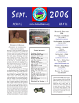
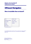
Figure 1 shows one representation of the main stages in the system design process.
Before a system can be designed, there must be a reason for it to exist; the objectives
of a system (considered in Stage 1) are normally formulated in very general terms (eg
navigate the driver to destination). The performance specifications describe what the
system needs to do to meet its objectives (eg transmitting both visual and auditory
information). These should reflect the context in which the system will be used and
the skills available among the users. The IVIS also needs to be compatible with the
primary driving task (ISO/DIS 17287, 2000). Stage 2 defines what functions need to
be performed to meet the objectives and performance specifications formulated in
Stage 1 (eg select destination, select route, provide directions, etc). In Stage 3 the
basic design is defined. After this, more attention can be given to the human-machine
interface in Stage 4. In Stage 5 attention is given to the documentation and training
that is needed for the end user. Testing and assessment (Stage 6) is typically
considered after this stage, but ideally should be carried out throughout the whole
design process.
1. Determine objectives
and performance
specifications.
2. Definition of the
system functions.
3. Basic design.
•
•
•
What functions need to be performed
(rather than how functions need to be
performed).
•
Allocation of function.
Specifications of human performance
requirements.
Task analysis/description.
•
•
•
4. Interface design.
•
5. Facilitator design.
Identify the intended users of the
system.
Identify and define user needs which
the system will address.
Characteristics of human-machine
interfaces:
Work space
•
Displays
•
Controls
•
Dialogues
•
Etceteras.
•
6. Testing and
assessment.
Materials that promote acceptable
human performance:
•
Instruction manuals.
Performance aids.
•
•
Training devices and programs.
Figure 1: Stages in design process (adapted from Sanders and McCormick, 1992)
8
Information about the system, user characteristics and how the system will be used
should be established early in the design process - and used to facilitate both the
design and assessment process. These principles are equally important where new
functionality is being added to existing functionality, to ensure that HMI issues are
considered for the overall integration of new and old. Human factors professionals
should be involved throughout the design process.
2.1.2 System requirements
Detailed design issues that need to be considered vary with the type of system or
systems being developed and their functionality.
At a very early stage of the design process a number of questions should be asked. For
instance:
•
•
•
•
•
What do drivers need systems to do?
What functionality must be provided by the system to meet these needs?
By what means did drivers address their needs prior to availability of the
system (eg use maps, listen to radio)?
What are the likely conflicts between system use and normal/safe operation of
the vehicle?
What functionality must be provided by the system to avoid misuse by the
driver?
2.1.3 System users
Information about which drivers the system is intended to help needs to be taken into
account in the design process and the system should ideally be designed with all users
in mind, whether male, female, young, old, able bodied or disabled. While some
systems are intended for all drivers, some will target particular groups. The type of
user may be characterised by driver demographics such as their sex and age or by the
reason for the trip. For example, holiday drivers might want to receive different
information to high mileage business drivers.
It is important to appreciate that drivers differ markedly in their physical, perceptual
and cognitive abilities and systems need to be designed with this in mind. Where
appropriate, these guidelines give special considerations to other user groups that have
distinct needs (eg the elderly). In addition, attitudes and emotional state will vary
between drivers and these may critically influence their behaviour.
Drivers do not perform consistently while driving; they experience lapses of
concentration, suffer from fatigue and stress (whether social, work or journey related)
- and sometimes consume alcohol. In contrast, drivers or developers undertaking an
on-road assessment of a new system may be highly motivated and focussed and
consequently unrepresentative of the wider user group. It should also be recognised
that driver behaviour during initial use (eg during testing and assessment) may be
very different from that adopted after the driver has habitually used the system for a
number of months.
9
2.1.4 Road and traffic conditions
The designer should recognise that the system will not always be used in the
conditions for which it was originally designed and that conditions can vary
markedly. Assessment should therefore involve a wide range of road and traffic
conditions.
2.1.5 Environmental conditions
Designers need to consider the range of environmental conditions in which their
systems are likely to be used. These should include darkness, bright sunlight, heavy
rain or fog, etc. Driving at night changes the driving task and IVIS design issues
considerably. Different lighting conditions also demand specific design features, for
example an anti-glare screen to compensate for bright sunlight.
2.2
SYSTEM ASSESSMENT
2.2.1 Importance of assessment
Designers should recognise that system assessment is important at all stages of
design, both for improved product development and to reduce potential liability
problems in the future. A formal assessment methodology or procedure should ideally
be applied to ensure a continuous and consistent assessment schedule.
It is advisable that user assessments (ideally with inexperienced users) are conducted
at an early stage in order to highlight unexpected circumstances of system use and
misuse. Even if an IVIS is created with careful adherence to design guidelines and
with consideration of user needs, it is advisable to conduct final usability trials using
both ‘naïve’ drivers as well as ‘experts’ who might have experience of similar
systems. Approaches to conducting assessments of safety and usability of IVIS are
described in sections 2.2.2 – 2.2.4.
If a new design is based on an existing system and is intended for use in the same
circumstances and by a similar group of drivers, then a limited assessment by
independent experts may be sufficient.
2.2.2 When to assess?
If the system uses elements that have not been tested in vehicles before, it is advisable
to assess the system's safety and usability early in the design process and again when
a prototype system is available.
In all cases it is advisable to plan and undertake assessment trials throughout the
design process. Tests should be conducted as soon as the first prototype systems are
available. Final tests must also be done to ensure the systems are safe for use while
driving. In some circumstances it may be possible to test pre-prototypes using
mathematical or structural models, mock-ups and simulated driving techniques.
10
2.2.3 Who should be involved?
Designers should involve suitably qualified and experienced ergonomic/human factor
personnel at all stages of any assessment conducted, either utilising appropriate
internal resources or engaging the services of external consultants where necessary.
Potential IVIS ‘end users’ should also be involved. The amount of training and/or
experience that these drivers have with the system will depend on what exactly is
being tested. If it is the comprehension of the system instructions provided that are
being assessed, then the users should be inexperienced. However, if the trials demand
driving in busy traffic then a certain amount of familiarity with the system would be
advisable.
Both male and female drivers, the young and elderly should participate. The required
number of drivers participating in the evaluation depends on the salience of problems
being investigated and their probability of occurrence (Lewis, 1994). It is unlikely that
a system evaluation would be effective using anything less than 10-12 end users
(Nielsen, 1993).
2.2.4 Assessment method and criteria
There are a number of general methods of IVIS assessment. One method considers the
ergonomic requirements of the specific IVIS design. A second method assesses the
IVIS ‘in-situ’ (but not necessarily on the road) according to human and system
performance criteria. Other methods can involve the use of focus groups,
mathematical models and user trials. The most appropriate method to use will depend
on when in the design process it is being applied and what aspect of the system is
being considered.
The first method is essentially a test of how well the system meets a set of design
guidelines, which may be performance criteria set by the producer. It may be based on
such requirements as the anthropometric and ergonomic standards for physical sizing,
locations of controls, and the labelling and display of information (see section 5) and
is usually conducted by human factors experts against some pre-specified objective
criteria. There are different systematic approaches to these expert evaluations such as
the TRL/DETR IVIS Checklist (Stevens et al., 1999) and the Heuristic Evaluations
method (Nielsen, 1993), both of which have been found to be effective for evaluating
IVIS. Both of these methods can identify key usability and safety issues. They give
problems a severity rating to guide re-engineering priorities and provide solutions
rather than just a critique. Both of these expert methods can be used very early in the
development phase and can be task-based or holistic.
A second method evaluates the system more quantitatively with respect to driver and
system performance. Although there is no single indicator for acceptable usability or
safety performance this method will need to take account of issues such as reliability,
validity and sensitivity (ISO/DIS 17287, 2000).
Reliability can be indicated for example, by two types of system error; errors of
omission where a stimulus is not detected, when the ‘hit’ rate for stimulus detection
should be high, and errors where a response occurs when no stimulus is present (false
alarms), when the false alarm rate should be low. Some examples of reliable and
validated measures are provided in Table 1 (on page 13).
11
Designers need to recognise that system assessment should never jeopardise the safety
of the participants (subjects), the evaluator or the general public. With this aim
desktop, laboratory or driving simulator assessments may be used to conduct
preliminary assessments and to identify more serious safety and usability concerns
before conducting trials in real road situations. In some cases it may be judged worth
conducting initial trials on a test track.
Ideally final safety assessment should be performed during road tests. It is also
necessary to tailor any assessment with respect to the existing situation or ‘base case’.
For example, if the IVIS provides route guidance it is necessary to consider whether
its use should be compared with traditional route finding techniques (with information
provided by road signs; and with or without the use of a conventional map - that
might be held or placed on the passenger seat). In this case test drives could be
undertaken, for example in an unfamiliar location, and compare performance of the
IVIS in relation to other in-vehicle tasks (eg tuning a radio). Note should be made of
all the difficulties encountered by drivers during these assessments.
There is also the complex issue of how to assess the balance between an IVIS that can
provide regular (possibly 'small') benefits over a long period of time, but may very
infrequently result in a single ‘extreme’ negative outcome. For example failing to
warn a driver about severe congestion on the route ahead, or instructing the driver to
make an illegal manoeuvre at a junction. This question is likely to depend critically on
the consequences (and/or frequency) of the system 'failure', although accurately
identifying such infrequent events during assessment trials conducted over a limited
period of time may prove very difficult.
Any significant degradation in performance when driving with the IVIS should be a
concern and if any basic safety related tasks are compromised the decision should be
taken to restrict their use to when the vehicle is stationary.
12
Table 1: Measures of IVIS Safety and Usability Performance
System Performance
Driver and Vehicle Performance
Driver
! Eye movement behaviour (eg mean and
maximum glance duration, glance
Efficiency
frequency, eyes off road time;
! Number of button presses.
Wierwille, 1993).
! Number of errors.
Task
success
rate.
!
! Situation awareness (Endsleigh, 1995a;
1995b).
! Task completion time (eg the '15
second rule', Green, 1999).
! Reaction time to events (eg peripheral
detection task; Olsson and Burns, 2000).
Driver workload
! Subjective rating/attitudes
(eg usability and usefulness ratings).
! Psychophysiological measures, (eg
heart rate and heart rate variability).
! Secondary task performance.
Vehicle
! Lane position variance (Tijerina et al
1995; Tijerina et al, 1998).
! Unplanned lane departures.
! Steering reversals.
! Steering and speed entropy (ie
unpredictable patterns).
! Mean speed, speed variance.
! Minimum headway and headway
variance.
! Minimum time to collision.
! Number of critical incidents and
crashes, speed on impact.
13
3
SYSTEM DOCUMENTATION AND USER INSTRUCTIONS
3.1 GENERAL
Designers should consider the advantages of providing systems where the need for
complicated instructions or training is minimal. The design process should recognise
the need to provide instructions, written or otherwise, for how the system can be used
– and (importantly) how it should be used without compromising safety. These should
be assessed (eg for comprehension) and cover all relevant aspects of installation,
operation and maintenance. Designers need to ensure that they play an active role in
the production of any manuals and documentation produced for end users.
Any instructions provided should be durable (European Statement of Principles,
1998) and contain the advice that they should be retained within the vehicle so that
future owners will be able to learn about the safe operation of the system. Instructions
should also inform drivers not to use the system until they are content that they have
(ideally) received sufficient instruction to do so safely or have at least had the
opportunity to familiarise themselves sufficiently with the system.
3.2 COMPLIANCE WITH REGULATIONS, STANDARDS AND
RECOMMENDATIONS
Standards and guidelines have been developed to assist designers and manufacturers
in producing usable products that meet the minimum safety requirements.
Documentation should therefore be developed and retained to provide evidence of
compliance with regulations, standards and recommendations and the consideration of
human-machine-interface (HMI) issues.
Regulations frequently relate to safe system use and crashworthiness in the event of
an accident. Thus, designers need to consider the safety of vehicle occupants and how
they can be protected from injury caused by the IVIS in the event of an accident.
3.3 PACKAGING INFORMATION AND INSTRUCTIONS
Designers and manufacturers of IVIS, whether ‘factory-fitted’ or ‘off-the-shelf’, must
not misrepresent what a system can do or how it should be used in a way that might
encourage unsafe use. This applies to both what the consumer is told at the point of
sale, and any publicity or other sales materials that are displayed or produced (EC
Code on Advertising, 1995).
Designers and suppliers should therefore ensure that the packaging accurately
conveys system functionality, and makes the user aware of system capabilities and
limitations. It should not encourage unsafe or illegal use nor create unrealistic
expectations on the part of the potential users; it should promote road safety and
compliance with existing traffic regulations, and recommendations for road and
vehicle use.
System instructions should be provided in the users native language, or a form
designed to be understood by the driver.
14
The instructions should:
•
•
•
•
•
•
be correct, simple and clear, relevant, well defined, and presented in a logical
order
clearly state which aspects of the system are intended for use by the driver
when driving, and those aspects that are not intended for use by the driver
when driving
identify the intended user groups, if specific skills or capabilities are required
or if the product is unsuitable for use by particular users
include actions required in the event of a system failure and a trouble shooting
(or help) section to easily locate specific information
state clearly that the driver retains absolute responsibility for the safe
operation of the vehicle and compliance with current traffic regulations,
regardless of any information provided by the IVIS
provide a statement of compliance with other systems.
Manufacturers should make the assumption that if they do not either directly stipulate
that a particular function should NOT be used while driving, or physically disable a
function when the vehicle is moving, then drivers are likely to assume it can be used
on the move.
In order to ensure the continued safe operation of the IVIS, and to ensure the drivers
are aware of their responsibilities, the user manual should outline the maintenance
requirements of the IVIS, including the frequency at which software should be
updated.
3.4 TRAINING
Designers should consider the advantages to be gained by integrating operating
instructions within the system – or even providing a programmed tutorial as part of
the system; although this will not always be appropriate or possible.
The possibility of providing a ‘hands on’ element to any training should also be
considered, either in the form of simulated use or an accompanied trial drive; again
this may not always be a realistic option.
15
4
SYSTEM INSTALLATION
4.1 DESIGNER/MANUFACTURER'S INSTRUCTIONS
Manufacturers and designers of IVIS intended for fitting into vehicles need to provide
clear instructions for the location and installation of the IVIS. These instructions
should be tested for comprehension on a group of end users. They should also take
adequate steps to ensure that those doing the installation are aware that any IVIS
should:
•
•
•
•
•
be located and fitted in accordance with the relevant regulations, standards and
manufacturers instructions for installing equipment in vehicles (UK Code of
Practice 2.1.1, EC Directive 74/60/EEC)
not be freestanding within the vehicle. Note that the EC European Statement
of Principles: Expansion HMI TF, 1998, does permit some devices (eg
automatic garage door openers) to be free-standing – but such devices do not
fit into the definition of IVIS employed here)
be easily usable from the driver’s preferred seating position
be fixed securely such that it is free from vibration
provide information on system compliance with any standards and regulations.
Designers also need to be aware that:
•
•
if the front seat passengers as well as the driver are likely to use the system
their use should not interfere with the driver in any way
IVIS need to be designed and installed in order to be crashworthy and to
minimise injury potential in the event of an accident.
4.2 PHYSICAL AND VISUAL ACCESS TO DRIVER CONTROLS AND DISPLAYS
Compliance with recommended control and display locations should ensure that the
driver’s ability to maintain full and safe control of the vehicle is not affected by
installation of the IVIS (BSI DD235, 1996). The system should be installed such that:
•
•
•
it does not obstruct or interfere with existing controls or displays required for
the primary driving task from the driver’s normal seating position
it does not obscure the driver’s view of the road scene through the windscreen,
side windows or rear view (EEC/71/127, EEC/77/649)
if the physical position of the system can be altered/adjusted so that it does
obscure the driver’s view, the manufacturer's instructions should clearly state
the intended position for use while driving.
4.3 COMPATIBILITY WITH OTHER SYSTEMS
Designers need to recognise that more than one IVIS system may be used in the same
vehicle. They need to be aware of, and consider the safety issues relating to physical
or electronic interference between systems and ensure that where systems are
16
integrated with a shared display, the system that is currently operational is clearly
identifiable by the driver.
Where a visual display is to be shared between different systems, conflicts between
the systems should not occur. In the event of a conflict arising the system should
prioritise and present any time critical information first. Similarly there should be no
conflicting auditory outputs from different systems or conflict between visual and
auditory messages.
17
5
DRIVER-SYSTEM INTERFACE: INPUT CONTROLS,
VISUAL DISPLAYS AND AUDITORY INFORMATION
5.1 INPUT CONTROLS
The primary function of a control is to transmit information (Sanders and
McCormick, 1992). The system controls should be designed so that they are easy for
the driver to use without adverse impact on the 'primary driving task' (see section
7.2.2). Adverse impact on the driving task occurs when badly designed controls
induce negative consequences on the ability to drive safely (Stevens et al, 1999).
In-vehicle controls should be designed for the intended user group. This requires a
clear decision as to who the user group is, together with compatible instructions and
publicity to support this decision. The user group may include disabled users, as well
as older (and weaker) drivers. Thus controls should be usable in all situations and
conditions that are likely to occur (eg in darkness, while wearing gloves). It is
therefore advisable that they be tested in such contexts. Safety critical design
decisions should be documented and reflected in user manuals.
Complex operations that require the use of both hands, or long un-interruptable
sequences of interactions (eg more than 5 keystrokes) should be disabled whilst the
vehicle is in motion (SAE 2364).
5.1.1 Location
Controls should be easy to reach from the normal driving position and should not
obstruct access to other driver controls or displays. They should not encroach upon or
interfere with normal leg, hand and arm movements, in order to avoid accidental
activation.
5.1.2 Layout
Each control should:
• Be usable without inadvertently activating another control.
• Be located in close proximity to their associated display.
• Be located so that the driver’s hand does not block his view of an associated
display.
• Move in a direction that is consistent with the display.
High priority controls should be easiest to reach and operate. The plane of the
displays and controls should be perpendicular to the driver’s line of sight.
The centres of controls that need to be operated non-visually should be positioned at
least 15 cm apart (Defence Standard 00-25 Part 10, 1992).
18
5.1.3 Design
The design of all controls used should be suitable for their function (see Table 2), and
thus the type of control will depend on the sort of information to be transmitted.
Controls that require fine control or adjustment (for example a stylus) or large forces
are unsuitable for in-vehicle systems that are used while driving, as are controls that
are designed for language or data entry such as keyboards.
Table 2: Selecting discrete controls (Adams, 2001)
Type
1. Linear
Push button
Slide
Toggle
Rocker
Push-pull
2. Rotary
Selector
Key operator
Thumb-wheel
Use
For brief 'one touch' activation of a function.
Where two or more positions are required along a continuum to
allow easy recognition of relative switch settings (eg auditory levels
across channels).
Where two positions (typically on/off, left/right) are required or
when space is severely restricted.
Where two positions are required and toggles may cause snagging
problems or where limited panel space makes separate labelling of
switch positions not possible.
Where two positions are required and such configuration is expected
or where panel space is scarce and related functions can be
combined (eg ON-OFF/volume control).
Three-position push-pulls should only be used where inadvertent
positioning is not critical.
Where three or more positions are required.
In two-position applications where swift visual identification is more
important than positioning speed.
In two-position applications to prevent unauthorised operation.
Where a compact digital control-input device with readout is
required.
5.1.4 Discernibility
Designers should ensure that controls are easily discernible during daylight and
darkness. They should use different methods to aid recognition such as using colours,
shapes, sizes, locations, textures, and (possibly) sounds. The advantages and
disadvantages of the different methods are set out in Table 3.
When different size controls are used to aid discernibility, these should be limited to a
maximum of three distinct sizes within one functional area.
19
Table 3: Advantages and disadvantages of different discernibility methods
(Adams, 2001)
Type of coding
1. Advantages
Mode of
operation
Location
Shape
Size
✓
✓
✓
✓
✓
✓
✓
✓
✓
✓
✓
✓
✓
✓
when
illuminated
when
illuminated
✓
✓
Improves visual identification
Improves non-visual identification
(tactile)
Helps standardisation
Aids identification under low levels
of illumination and coloured lighting
May aid in identifying control
position (settings)
Requires little (if any) training: is not
subject to forgetting
✓
✓
✓
✓
Labelling
✓
Colour
✓
✓
2. Disadvantages
May require extra space
Affects manipulation of the control
(ease of use)
Limited number of available coding
categories
May be less effective if operator
wears gloves
Controls must be viewed (ie must be
within visual areas and with adequate
illumination present)
✓
✓
✓
✓
✓
✓
✓
✓
✓
✓
✓
✓
✓
✓
✓
✓
✓
✓
✓
Controls should be separated by distances that are sufficient to avoid two buttons
being pressed inadvertently. It should be recognised that drivers may have different
manual dexterity, on occasions may not be able to devote total concentration and may
sometimes be wearing gloves. In order to avoid confusion between positions there
should be more than 2.5 cm between button centres (but also see section 5.1.2). For
size coding to be effective, controls must be sufficiently different in size to make
them different from each other (see Table 4).
Table 4: Minimum dimensions for finger operated controls (MIL STD-1472F,
1999).
Type
Push-button
Operation Dimension
g force
1 to 8 N
8 mm
Contact surface Clearance (centre to centre)
area
Gloved hand
Bare hand
2
80 mm
25 mm
15 mm
5.1.5 Control input stereotypes
Controls should be designed in conjunction with conventional stereotypes. For
example, turning a control clockwise is normally associated with ‘up’, ‘right’, or
‘increase’, while counter-clockwise is associated with ‘down’, ‘left’, or ‘decrease’.
Under highly stressful or high workload situations, people often refer back to learnt
20
stereotypes, and if what they perceive does not meet their expectations, they are more
likely to make mistakes.
5.1.6 Colour
Colour should be used effectively to aid the layout of controls. The meaning of the
colour coding should be clear and should conform to stereotypical norms, for example
red for alarm and amber for warning. Red/green and blue/yellow combinations
should be avoided since these colour combinations might be confusing for people who
are colour blind. The use of too many colours should also be avoided, a maximum of
five different easy to distinguish colours is recommended (BS 5378 Part 1, 1980).
Colours should be used consistently throughout the system. Colours should have the
same meaning on all the screens that the system can use.
It should be noted that when using colour visual displays colour after effects can
occur (such as the McCullogh effect which causes “pink snow” if green text has
previously been read). ‘Floating’ of display elements can also occur with high colour
saturation, thus colour must be used with care and with due consideration to changes
caused by variations in luminance and contrast.
5.1.7 Lighting
The lighting of the controls should be adequate to identify the required control but
should not distract the driver. Drivers should be able to adjust the level of lighting.
5.1.8 Feedback
Control operational feedback should be adequate, appropriate and timely. Operational
feedback is adequate if it is obvious to the driver that a change has occurred in the
system and that this change is a consequence of the input. A timely response should
usually be given within 250ms (European Commission, 1998).
The user should be able to hear or see immediately if they have made an input error or
incompatible choice.
The system should provide error messages in plain language and indicate the precise
problem. It is even more important for the system to inform the driver accurately
about any malfunction of the system.
Examples include when an address is entered that does not exist, the error message
should say 'address does not exist', rather than 'error input'. When the sensor
calibration data is lost, the system should inform the driver that accuracy of the route
guidance system is reduced.
There can be safety implications when there is a difference between the actual
function of a system and the driver's expectations based on previous information and
experience. Therefore it is important for the system to make it clear to drivers when
there is a change in status or a malfunction which modifies the system's performance,
so that drivers can modify their behaviour accordingly.
21
5.1.9 Touch-screen controls
Current generations of touch-screens are not appropriate for use when mobile since
they provide no tactile feedback concerning control orientation, location, separation
from one another, or function, and consequently cannot be accurately operated 'eyes
off'. Interaction with touch-screens often demand long glance duration, and
consequently a high degree of visual resource allocation in order to locate and activate
the control button; this type of interaction is not conducive to safe performance of the
driving task.
If touch-screens are used in vehicles, they should be simple to use and suitable for the
function they serve, the controls (unless extremely simple, such as on-off) should not
work by ‘proximity’ but require light positive pressure for activation and provide
auditory control activation feedback. Screens activated by proximity detection make it
easy to inadvertently activate the wrong control; unless the responsive areas are very
large.
5.1.10 Voice operated controls
Designers should note that speech recognition systems may not yet be sufficiently
advanced to implement reliably in vehicles (Khalid and Helander, 2001). Those
currently in use tend to have limited vocabularies and are not robust enough to
provide high recognition accuracy, leading to frequent misinterpretations.
Additionally, vehicle and passenger noise often interfere with the voice recognition
system, while changes in people's voices due to fatigue and stress can make valid
commands unrecognisable (Sanders and McCormack, 1993).
When using speech recognition systems:
•
•
•
•
5.2
the vocabulary used should be familiar to drivers and should avoid using
similar sounding words or phrases
the system should give immediate feedback (ie within <250 ms) to the driver
in regards to the recognition results
the systems recognition accuracy should be high, particularly in safety critical
situations (eg recognition 98% for hit rates and less than 5% false alarm rates)
the system must be able to cope with expected amounts of background noise.
VISUAL DISPLAYS
5.2.1 General
Designers should note that visual information presentation is the most appropriate
modality to use when information is complex, does not require immediate action, may
need to be referred to again and/or is presented continuously (Sanders and
McCormick, 1993). When possible and appropriate the use of both visual and
auditory information presentation should be used.
Visual information presented on the IVIS should appear legible, accurate and be
presented at the appropriate time. The size of the display images should be
appropriate to their function. High priority visual information requiring immediate
22
action should be more prominently displayed and should be accompanied by an
alerting auditory tone (Campbell et al., 1998).
5.2.2 Location
For a driver to be in full control of the vehicle and aware of the dynamic road scene,
there is a broad consensus that, apart from brief glances at mirrors or instrumentation,
the driver's gaze should be directed towards the road scene. Visual displays positioned
close to the driver’s normal line of sight reduce the total eyes-off-the-road time
relative to those that are positioned further away. Such positioning also maximises the
possibility for a driver to use peripheral vision to monitor the road scene for major
developments while principally looking at the display.
The higher priority the information has, the closer it should be located to the normal
line of sight. The driver's normal line of sight refers to the direction of the driver's
gaze out of the front windscreen onto the road ahead. Visual displays showing high
priority information during driving should be located within 15° of the driver's
vertical viewing position and ideally 15° horizontally (HARDIE, 1996) with a
maximum separation of 30°.
Priority should be based on the display's relevance to driving, criticality, urgency and
frequency of use. This may require trading-off various functions at the design stage
(ISO/CD 16951 N287, 2000).
Displays showing high priority information and multifunction integrated visual
display screens should be located high on the dash-board and not low in the centre
stack console. Only very simple information that is rarely used by the driver should be
located in the centre stack console.
5.2.3
Legibility
5.2.3.1 General
To ensure legibility of information the designer needs to consider not only the
position of the visual display, but properties such as brightness, contrast, size and
resolution. These should be such that the displayed information is clearly legible
during daylight and darkness and does not cause visual discomfort or distract the
driver when not being directly viewed.
5.2.3.2 Brightness
The brightness (luminance) of the overall display should appear uniform to drivers.
While in some conditions the overall uniformity of display luminance may vary, it is
best to avoid this within a particular element of the display (eg a sentence).
The brightness of the display should be adaptable to changes in ambient light (eg day
or night) to ensure that the display is legible in all ambient light conditions.
23
5.2.3.3 Contrast
The contrast ratio (see formula below) describes the relation between the luminance
of the foreground and background. This should be a minimum of 3:1, whilst a ratio of
5:1 is recommended (HARDIE, 1996). Too high contrast can cause problems of
glare, while too low contrast slows down the reading process. The ratio of area
average luminance of the display and of the surrounding (luminance balance) should
not exceed 10:1 (ISO 15008 integrated, 2000).
Contrast =
Lforeground - Lbackground
Lbackground
Lforeground = Luminance of the foreground
Lbackground = Luminance of the background
Reflections and glare visible to the driver on both displays and windscreens reduce
legibility, and should be avoided for example through:
•
•
•
•
•
provision of a display brightness control
appropriate display surface texture and finish
appropriate colour choice
appropriate image polarity
use of a recess or cowl.
Designers should ensure that any reflection and glare reduction, or contrast
enhancement techniques of this type, do not cause the display to contravene other
relevant standards.
5.2.3.4 Resolution
The resolution of the display should be high enough to show the driver solid images
of information via symbol or text. The number of pixels measures a display's
resolution. The single pixels of a display tie together to form a contour of a picture
(text or symbol). With an increasing number of pixels, the contour of the picture will
appear clearer (HARDIE, 1996).
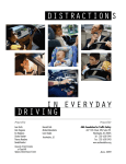
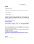
5.2.3.5 Character and spacing
Characters used in a display should be large enough to read in the moving vehicle.
H
W
S
Figure 2: Character height, width and stroke
24
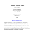
The minimum required character height (see H in Figure 2) should be a visual angle
of 15'. This angle describes the relationship between the viewing distance and
character height as shown in Figure 3. The following equation should be used to
determine the required character height:
H = tanα x D
H = character height in mm
α = angle created at the eye by the character height and distance from the display
(see Figure 3)
D = distance from the driver's eye to the display in mm.
The minimum requirement of 15' is recommended for static or non-critical
information (Mourant, 1976). Since a vehicle is in motion and vibrates, reducing
legibility, it is recommended that character height is at least 24' (ISO 15008
integrated, 2000). With a visual angle of 20' at a normal reading distance in a vehicle
(700mm) the minimum character height would be 4 mm.
Angle (α)
character height
eye
distance from driver to display
Figure 3: Minutes of arc.
The ratio between the stroke width (see S in Figure 2) and character height should be
between 1:12.5 and 1:6.25. The ratio should be lower for more prominent, dynamic
and safety critical information. The more critical the information, the wider the
character should be (up to a ratio of 1:6.25).
The width of a character (see W in Figure 2) is very dependent on the height of that
character. The relation between the width and the height of the character should be
between 0.5:1 and 1:1, whilst a ratio between 0.6:1 and 0.8:1 is recommended. A
wider symbol should be provided for more prominent, dynamic and safety critical
information. The more critical the information, the wider the character should be, up
to a ratio of 1:1.
Character spacing refers to the horizontal space between adjacent characters. This is
usually expressed in terms of the stroke width of the characters. The space between
the characters should be a minimum of one stroke width. Wider spacing should be
used for more prominent, dynamic and safety critical information. The more critical
the information, the wider the spacing should be; although legibility will be reduced if
it becomes excessively large.
25
5.2.3.6 Font
The type of font used to display text is an important factor in legibility and
comprehension.
•
The font type should be clear and simple. Sans serif fonts are recommended (eg
Arial, Helvetica; not Times).
•
No more than two different fonts and two types of emphasis (eg bold or
underlining) should be used (HARDIE, 1996).
5.2.3.7 Case
• The use of mixed (or 'sentence') case with a ('standard') combination of lower and
upper case letters makes characters and messages more easily recognisable; and
should be used for written text rather than using all capitals or lower case.
•
However, if resolution is low (eg less than 32 x 32 pixels) and 'descenders' (eg 'p',
'g', 'y', etc) are not possible - the use of upper case only may be considered as a
(second best) alternative.
5.2.4 Colours
Colours should be:
•
•
•
coded such that their meaning is clear and should conform to stereotypical
norms (DIN EN 60073, 1997)
used to make it easier to find the required information under both day and
night-time viewing conditions
chosen so that red/green and blue/yellow combinations are avoided.
Colour should not, however, be used for actual messages, as this would increase the
reading time.
The use of too many colours should also be avoided. A maximum of five different
easy to distinguish colours is recommended (excluding black and white).
It may be appropriate to have three levels of priority indicated by colour, eg 1) Red –
Alarm, 2) Amber – Warning and 3) White – Information/ status.
5.2.5 Symbols and graphics
The use of graphics and symbols should be appropriate to their function and should
conform to stereotypical norms. The advantages with symbols compared with text are
that they erase language barriers and can be recognised faster and from a greater
distance.
The graphics features or symbols should be consistent throughout the IVIS system
and should not be too detailed or complex, as this can increase the time taken to
identify appropriate information.
26
•
•
•
•
•
Where possible, the graphics features should be functionally grouped, but not
cluttered.
When unfamiliar symbols are used, a text label of limited text should
accompany them, but should otherwise be avoided.
For ISO 2575 symbol and tell-tales, or similar, a matrix 32 pixels x 32 pixels
is the minimum (ISO 9241-3).
Commonly accepted or standardised symbolic icons should be used (Campbell
et al., 1998; ISO 4040).
The comprehension of non-standard and unfamiliar symbols should be tested.
5.2.6 Screen image stability
The screen display should not vibrate or flicker to an extent where information
becomes blurred, (the eye is capable of detecting luminance flicker of up to 90Hz in
some circumstances). Vibration or flicker are likely to increase reading time and
consequently the time required to complete the task and thus will increase visual
distraction from the driving task (HARDIE, 1996).
5.2.7 Image blinking
Blinking (or flashing) of any visual image should only be used to attract attention and
inform about critical conditions. For attracting attention, a single blink frequency of 2
to 3Hz with a duty cycle of 50% is recommended. If legibility of the displayed
information is required, a single blink rate of 1/3 Hz to 1Hz with a duty cycle of 70%
is recommended (ISO/DIS 15008). It is inadvisable to use blink rates of 4Hz or
greater since these may cause physiological discomfort, including nausea and
dizziness. Adjacent blinking areas can also produce motion and metacontrast effects
that might be distracting.
5.2.8 Scrolling displays
Scrolling is used when information is too large to fit onto one screen. It usually
requires sustained visual and manual interaction, or, in the case of a series of
automatic sequentially scrolled displays, numerous sustained glances. Scrolling is
therefore not suitable to use within the driving environment.
5.2.9 Head-up displays
Head-up displays (HUD) consist of a virtual image that is optically superimposed on
the driver’s forward field of view, using either the windshield or a separate optical
element.
The safety benefits of HUDs are generally small and in some instances HUDs
produce poorer performance (Gish and Staplin, 1995). Therefore the following
guidelines should be followed:
•
•
•
do not present the HUD image in the driver’s central field of view as it will
mask external objects
drivers should be able to turn the HUD off
important HUD information should be coupled with an auditory alert
27
•
•
•
•
•
while the HUD image must be visible in all potential viewing conditions,
luminance contrast requirements for HUDs are a concern because of the
dynamic interference with the background road traffic environment
virtual image distances should be between 2.5 to 4 metres from drivers’ eyes
information should only be displayed temporarily in the HUD. The HUD
should not be used to display information continuously
HUD displays should not be used to present complex information, for example
detailed navigation information that cannot be processed quickly, rather, a
simple display with very few elements should be used
use images that conform to the road environment (eg virtual road signs
projected by the roadside).
5.2.10 Message
Messages presented while driving should not consist of more than four units of
information. Concrete words which have clear meanings should be used whenever
possible (McDougall, 2001).
Numerical data should use accepted and understood units; and provide an appropriate
level of precision.
Abbreviations should only be used when it is necessary; and should not be used for
safety- critical information. Where abbreviations are used, these should be widely
known, have clear meaning, be used consistently and conform to national
conventions. Where available, internationally and nationally agreed standards related
to abbreviations should be used (European Commission HMI TF, 1998).
Safety critical information should be given in a command style. However, the
command style should be used infrequently.
High priority messages, such as immediate hazards or vehicle status warnings, should
be preceded by an auditory alerting tone.
Messages that convey non-critical information should be given in an informative
style.
5.3 AUDITORY INFORMATION
5.3.1 General
Designers should only consider the use of auditory information when this is the most
appropriate modality for the type of information being delivered. Auditory
information is most suitable when the driver's attention needs to be gained, when the
message is short and simple and does not need to be referred to later. Where possible
and appropriate, the combination of visual and auditory information presentation
should be used.
Ideally the system should enable the last auditory message to be repeated by means of
a simple button press, or voice command, as the driver may have been distracted
28
during the initial presentation of the auditory information, or may have forgotten or
not have understood the message.
It should be possible to control whether the auditory information is turned on or off
and feedback about the current status of the auditory information should be presented
every time the system is turned on.
5.3.2 Volume
It should be possible to hear the auditory output under all driving conditions at a level
that will not startle the user. The volume of auditory output should be adjustable over
a reasonable range; in most circumstances between 50dB(A) and 90dB(A) is suitable.
Higher than 90dB(A) should be avoided.
Sounds containing different frequencies should all be presented at an appropriate
volume, usually this can be achieved if the signal exceeds the ambient noise by 15 dB
or more (Sorkin, 1987). However, to avoid a startle response, the signal should not
exceed ambient noise by more than 25dB (Edworthy, 1994). The signal level is a
matter of balancing the listener comfort against message audibility.
5.3.3 Frequency
Auditory information should always lie within the range of human hearing (ie 200 8000Hz), but it is recommended in practice that it should lie between 500 and 4000Hz
(ISO 15006-1). It needs to be designed, however, such that a driver is not prevented
from hearing interior or exterior warnings.
5.3.4 Auditory information presentation
When multiple sounds are used within complex systems, the sounds should be
designed as an integrated set. By doing so, the audibility of the signals with one
another and background noise can be optimised (Robinson, 2001).
5.3.5 Speech
Designers should ensure that when using speech to convey messages:
•
•
•
•
•
•
the system should give immediate feedback (ie within <250 ms) to the driver
messages should be short and simple and should not need to be referred to
later
if messages cannot be presented in a short sentence, the most important
information should be presented at the beginning of the message, and could be
repeated again at the end
the vocabulary used should be familiar to drivers and should avoid using
similar sounding words or phrases
messages that require an urgent action should be a single word or a short
sentence and should be understood immediately
the system should be able to cope with background noise and should not be
influenced by it, a signal to noise ratio (SNR) of around 5dB(A) should be
sufficient to ensure audibility (ISO/CD 15006 1996)
29
•
where messages contain instructions, they should be presented in a logical
order for example rather than ‘turn left in half a mile, the message should be
‘in half a mile, turn left’.
30
6
DRIVER-SYSTEM INTERFACE: DIALOGUE
MANAGEMENT
6.1 GENERAL INFORMATION PRESENTATION
In general there are four types of information that can be conveyed to the driver
(Galer, 1983):
•
•
•
•
warnings
advisory information
diagnostic information
entertainment.
Warnings provide information that is of vital importance to the safe operation of the
vehicle and in-vehicle systems. Advisory information is also useful for the safe
operation of the vehicle and in-vehicle systems, but this tends to be vehicle status
information that is less time critical and severe (eg telltales). Diagnostic information
explains the condition of the vehicle for maintenance purposes. Some vehicle
information can also be provided through the entertainment system (eg traffic
bulletins via the audio system).
System design should ensure that information presented to the driver should be
correct, consistent and compatible with the road network. The quantity of information
presented to the driver should not be excessive.
When it is not possible for the driver to comply with the IVIS instructions, the driver
should be clear about how the system will respond. Ideally the system should
recognise the failure to respond and compensate for the non-compliance by offering a
confirmation message and updated advice.
6.2 VISUAL INFORMATION PRESENTATION
Designers should ensure that when the in-vehicle system consists of different
functions (eg route guidance, entertainment and e-mail), these should be fully
integrated. Preferably the system should have one interface, and features such as
colours, formats, and menus should be consistent throughout the different functions.
This is a particularly important consideration if drivers have access to information
from 3rd party providers (eg through the Web portal).
A display should be organised in such a way that drivers can direct their attention to
the relevant information and find it easy to understand and respond to that
information. The display should therefore be simple in overall density, local density,
and grouping:
•
•
overall density: the percentage of the total number of characters or symbols
that could occur in the display space. High information density may cause
overload and increase errors and difficulties in finding appropriate information
local density: the amount of space that is filled around a symbol/item. Blank
space provides structure in a display
31
•
grouping: considers how close items are and how likely it is that they are
perceived as groups.
On first sight of a visual display, areas of high contrast attract the attention. Contrast
between different parts of the display should therefore be created where appropriate to
aid the direction of attention, and understanding of the information being presented
(McDougall, 2001).
6.3 CHOICE OF DISPLAY MODALITY
Designers should avoid presenting complex visual information to the driver of a
moving vehicle if possible. A visual display should only be used if this is more
compatible with the function than other modalities, such as speech.
The driver should be able to assimilate visual information with a few glances, which
are brief enough not to adversely affect driving. A brief glance refers to glance
duration of around 1 second representing the normal case and a maximum single
glance of 1.5 seconds (Wierwille, 1993).
If the system provides non-safety related dynamic visual information (for example
navigation, parking or traffic information), it should be possible to be switched into a
mode where that information is not provided to the driver of a moving vehicle.
Non-driving related information (eg TV or video) should be disabled or presented in
such a way that the driver cannot see it while the vehicle is in motion (DD235, 1996).
6.4 INDIVIDUAL PREFERENCES
Designers should recognise the advantages of systems that allow drivers to tailor the
presentation of information to their own preferences and driving requirements,
especially for information requiring direct responses. Although drivers should not be
able to do this whilst driving and available options should be within reason. The
setting of personal preferences should, however, be restricted within safe limits in
order to prevent the inadvertent loss of information.
When maps are displayed within the vehicle, the system should distinguish clearly
between system modes. For example it should be clear when the vehicle is in the
middle of the display (re-centred map mode), or when the vehicle moves relative to
the stationary map (normal display mode).
6.5 MENU FACILITIES
It should be easy to navigate through the system menus. It should be simple to return
to the start or escape from a dead end. These options should be consistent throughout
the system.
There should be an appropriately small number of menus, submenus and final options.
The number of choices per menu should be limited to three or four. Frequently used
functions should have dedicated single function control keys rather than be located
within the system menu structure.
32
For interactions involving more than one screen, the driver should not have to
remember information from one screen to the next.
6.6 TEMPORAL INFORMATION
The system’s response to driver input should be timely (see section 5.1.8) and clearly
perceptible. If a response takes longer than 250ms, the system should inform the
driver that it has recognised the input and is busy preparing a response (European
Commission, 1998).
Visual information should be presented for a sufficient length of time that allows the
driver to observe it in their own time when other task demands are low, or remains
displayed / re-presentable, until the driver acknowledges that he has observed it, or
the message becomes out of date.
The IVIS should be free from 'machine-pacing'. The driver should be able to control
the pace of the interaction with the system. It should be possible to interrupt a
sequence of interactions and resume again at the point of interruption or at another
logical point.
When new information arrives that is directly relevant to the current driving situation
(eg a coming turn), a suitable indication should be given in advance of a driver
decision. Two or three messages should be used sequentially including the time
and/or distance to the event.
6.7
CONSISTENCY
Information presented to drivers should be consistent and compatible with the road
network. Consistency is also how well a system matches a driver’s expectations. IVIS
handling, appearance and behaviour should conform to the driver’s expectations. The
driver’s expectations can be a function of their experience with the system or similar
systems and commonly accepted conventions. Expectations will also vary with
individual differences such as knowledge, culture and gender.
Message terminology and icons should be consistent between displays. Colours
should be consistent between displays of similar function. Controls should behave
consistently. Avoid changing modes where user interaction requires different actions
than in other states (eg adaptive multifunction buttons). Organise data fields to match
user expectations.
Inconsistent systems, ie those that do not match driver expectations, will be more
difficult to use and take more time to learn. Inconsistent systems will cause more
errors. The severity of this problem will depend on the system function.
6.8 SIMPLICITY AND QUANTITY
Simplicity refers to the ease with which IVIS tasks are performed and information
understood. IVIS systems should not allow or demand any complex tasks. The
amount of information on display should therefore be restricted. Complex IVIS tasks
33
will distract the drivers’ attention from the primary task. This will reduce driving
performance and compromise road safety.
Visually displayed information should be such that the driver can assimilate it with a
few glances that are brief enough not to adversely affect driving. If the information
cannot be acquired in a few brief glances driver workload and visual distraction may
increase. Driving is adversely affected when the driver is distracted or overloaded
which, may result in situations where their actions, or lack of actions, increase the risk
of a crash.
In order to maintain simplicity the following principles should be adopted (European
Commission, 1998; BSI, 1996):
•
•
•
•
•
•
•
•
•
•
use single words or simple and familiar icons where possible
dialogue should not contain information that is irrelevant or rarely needed.
Every extra unit of information in a dialogue competes with the relevant units
of information and diminishes their relative visibility. Eliminate unnecessary
information
maintain display inertia - make sure the screen changes little from one screen
to the next within a functional task situation, unless new information is being
presented
use concise, unambiguous wording for instructions and messages
use a balanced screen layout with plenty of 'white space' around text blocks (at
least 50% 'white' space for text screens)
keep backgrounds simple and muted
group information logically
structure the information rather than just presenting a narrative format.
Organise information into a small number of "chunks"
functionality should be clear. Hidden functions tend to stay that way
allow users to tailor frequent actions.
6.9 SYSTEM DIALOGUE IN A MOVING VEHICLE
System dialogue refers to the communication and interaction between the driver and
IVIS. Only IVIS tasks that do not directly or indirectly increase the risk of collision or
injury to vehicle occupants or other road users may be suitable for use while driving.
Complex information and control actions should not be designed for use in a moving
vehicle because they can be too distracting for the drivers. Guidelines to be followed
include:
•
•
•
•
any IVIS functions that are accessible, but not designed for use when the
vehicle is in motion, must be clearly indicated as being restricted
long sequences of interactions with the system should not be required. Drivers
should be allowed to interrupt the sequence at any time without consequence
there should be a balance between the breadth and height of menus. The
number of choices should be limited to three or four options to minimise the
complexity and interaction time
an 'off' or 'mute' option should be available
34
•
•
•
•
•
•
•
system response (eg feedback, confirmation) to driver input should be timely
(< 250ms) and clearly perceptible
avoid unnecessary attention-grabbing techniques (eg Boeing's Dark and Silent
cockpit metaphor: 'Do not blink or beep unless absolutely necessary')
prioritise information
no low priority system initiated information
drivers should be able to initiate and control the pace of interaction with the
system; no time-critical responses should be required when providing input to
the system
keep the user informed about system status
do not display information when the driver is busy, although this guideline is
for more advanced “intelligent” systems, eg GIDS (Michon, 1993).
If an IVIS task is too distracting, it can either be re-designed or removed. Complex
IVIS functions can be locked out to prevent in-transit use. These functions should be
accessible only when the vehicle is stationary.
35
7
OTHER SAFETY RELATED ISSUES
7.1 GENERAL
There are a number of general safety issues that need to be taken into account in the
design of IVIS. The main concerns are driver overload and attentional demands that
can distract the driver from the primary driving task. Systems can be a hazard to
safety if they are not designed to be compatible with driving.
The use of in-vehicle systems must not directly or indirectly increase the risk of
collision or injury to vehicle occupants or other road users. Drivers must be able to
use in-vehicle systems easily, effectively and satisfactorily; and in a way that is
compatible with and suitable for driving.
In order to be safe and compatible with driving, IVIS must have good usability and
not be distracting. Some IVIS design guidelines for optimising ease of use and
avoiding distraction are presented in this section.
7.2
DRIVER DISTRACTION
7.2.1 Definitions
In order to understand how a driver might be distracted from a task, it is first
necessary to introduce the concept of 'attention' (to a task). Attention has been defined
as the selectivity of cognitive processing that involves focussing or concentrating on
one area of thought in order to deal with it effectively (Eysenck, 1994). When drivers
attempt to attend to more than one stimulus at a time, their attention becomes divided;
and if a secondary task is difficult or demanding they may become distracted from the
primary task.
The literature provides a number of definitions for distraction. Janssen (2000) used
distraction to refer to the capture of the driver’s attention by information that is
irrelevant to the driving situation to a degree where insufficient attention is left for the
primary task. Ranney et al (2000) defined driver distraction as any activity that takes
a driver’s attention away from the task of driving. Some authors use driver distraction
to mean the allocation of attention to the system displays or controls that has a
negative effect on driving performance.
7.2.2 Driving
The primary task is to monitor and control the vehicle’s lateral and longitudinal
position along a safe path. At the simplest level this involves controlling steering and
speed, tasks that with time and experience become almost automatic requiring little
cognitive effort. At more complex levels additional manoeuvres will be required, for
example overtaking, and manoeuvring appropriately at junctions and roundabouts.
These tasks demand greater cognitive effort and the introduction of additional
information for example from a route guidance system while undertaking these tasks
will create an unwanted distraction (Allen et al, 1971; Tijerina et al, 2000).
A distraction can be visual, auditory, cognitive or biomechanical (Ranney et al, 2000).
Something that takes driver’s visual attention away from the road or changes their
36
glance behaviour is a visual distraction (eg reading a map). Listening to music while
driving could be an auditory distraction. An activity that demands thought can be a
cognitive distraction if it takes the driver’s mind off the road traffic environment (eg
engaging in a call on a hands free mobile phone). Something that requires the driver
to lean forward, take their hands off the wheel or stretch to operate can be a
biomechanical distraction (eg adjusting the volume on an entertainment system).
These biomechanical distractions can force drivers off their normal sight lines and
impair their control of the vehicle. Many distracting activities that drivers engage in
can involve more than one of these four components. For example, tuning the radio or
dialling a mobile phone may involve all four components of distraction.
Distracted drivers are more dangerous because they may be unable to adequately
monitor and control the vehicle’s safe path while performing an IVIS task. It is the
coincidence of driver inattention and the occurrence of unanticipated events (eg curve
in the road, pedestrians crossing) that causes distraction-related crashes (Ranney et al,
2000).
The driver may try to regulate the consequences of distraction by reducing the
attentional demands of the driving task in terms of lowering the amount of effort
required to perform it and its level of difficulty for example by slowing down.
However, there will be times when this type of regulatory behaviour is not possible,
for example when making judgements about time-gaps at intersections.
The system should be designed in such a way that the allocation of driver attention to
the system displays or controls remains compatible with the attention demands of the
driving situation.
7.3 SYSTEM FAULT AND INPUT ERROR WARNINGS
If the IVIS is inoperative at the start of a drive (when activated by the driver), or fails
during it, the driver needs to be made aware of the situation.
Drivers will make mistakes while using IVIS, so the systems must be tolerant of user
input errors. It must be possible to easily recover from errors and the consequence of
potential errors must be minimised. Error messages should be expressed in plain
language (no codes), precisely indicate the problem, and constructively suggest a
solution. Some other guidelines for system faults and warnings are (European
Commission, 1998 and ISO 15005 - currently being approved):
•
•
•
•
•
•
•
the driver should have immediate and clear feedback for input errors
use reminders, or warnings only as appropriate
provide user-centred wording in messages
avoid ambiguous messages, use plain language and indicate the precise
problem
avoid using threatening or alarming messages unless appropriate
use specific, constructive words in error messages (eg avoid general messages
such as 'invalid entry' and use specifics such as 'please enter your name')
make the system 'take the blame' for errors (eg systems should respond
'unrecognised command' rather than 'illegal command')
37
•
•
avoid automatic switching to other modes when desired functions become
inaccessible
make user actions easily reversible, allow 'undo' commands and other escape
routes from operations.
7.4 BEHAVIOURAL ADAPTATAION
Another safety concern for IVIS is behavioural adaptation; as drivers become more
familiar and experienced with a particular system they may adapt / modify the way in
which they interact with it and the information it provides.
The Organisation for Economic Co-operation and Development (OECD, 1990), refers
to behavioural adaptation as those "…behaviours which may occur following the
introduction of changes to the road-vehicle-user system and which were not intended
by the initiators of the change". Designers should consider that potential safety
benefits and behavioural impact of new in-vehicle systems may be reduced by
behavioural adaptation; for example, drivers may consider using route guidance
systems to help them find their way in fog when without the IVIS they would not
travel.
In this context the more advanced and sophisticated the system – and the more useful
information it offers the driver – the more such adaptation and reliance will become a
factor. The only effective way of assessing – or evaluating – such concerns are by
instigating long-term trials.
7.5 ACCURACY OF INFORMATION
Designers need to recognise that presenting drivers with inaccurate – or untimely –
information is likely to have serious safety implications in some circumstances. In
general it is advisable not to present inaccurate information and to ensure that a
system will fail-safe.
Systems need to take into account the accuracy of the information provided by
external sources, for example GPS for vehicle positioning, and allow for possible
inaccuracies in this information.
As well as being accurate information also needs to be unambiguous and not open to
misinterpretation by the driver.
7.6 ROUTING AND SAFETY
System design may need to take account of a changing road network. The IVIS needs
to be able to deal with:
•
•
•
temporary diversions (eg caused by road works or accidents)
minor changes to network (eg new one-way systems)
upgraded roads (eg from single to dual carriageway).
38
If drivers are required to leave the suggested route the system needs to recognise this
and ‘recalculate’ the route guidance provided.
If ‘maps’ are used they will need to be updated on a regular basis. Designers should
build in provision for updates and notify the user of how this will be done.
39
8
THE LEGAL SITUATION (FOR UNITED KINGDOM)
These guidelines deal with the current legal situation with regard to IVIS, that apply
in the United Kingdom, although similar provisions do apply throughout Europe.
When examining the legal situation concerning any new in-vehicle device, it is
necessary to consider each of the following:
•
•
•
•
•
•
•
Responsibilities.
Traffic law.
Licences and contracts.
Type approval.
Tort liability.
Consumer protection liability.
Health and Safety at Work Act.
8.1 RESPONSIBILITIES
Each person, or organisation, in the IVIS supply chain has responsibilities to ensure
that systems do not compromise either the safety of the users themselves - or of other
road users. Importantly they may be required to prove that they properly fulfilled their
legal responsibilities in a court of law in the event of some improper functioning,
confusing information or breakdown resulting in an injury or accident taking place.
This applies not only to those supplying the system – or possibly installing it – but
also employers expecting their staff to use the system and vehicle hire companies
renting or leasing vehicles who should also accept responsibility for maintaining or
repairing any system fitted in their vehicle – or at least warning drivers that a fitted
system is not functioning properly. While it can be argued that drivers themselves
bear the ultimate responsibility for their own (and other road users) safety, it can also
be debated whether they were given sufficient verbal guidance or advice (or written
instructions) about safety aspects of the IVIS. Ideally a copy of the manufacturer’s
user instructions should be provided (and remain) in every vehicle.
The provision and use of in-vehicle information systems needs to comply with a
variety of complex legal issues that deal with human machine interaction, driver
behaviour, responsibility and safety. Systems must comply with the rules that allow
vehicles and drivers to be part of public road traffic and the rules of traffic law. Also
the civil and penal liability of the driver/keeper of a vehicle and the rules on the
product liability of manufacturers and suppliers are relevant.
Drivers should ensure that they have access to manufacturers' instructions and take
adequate steps to be aware of their content before driving on the road. They should
not use a system until they are able to do so safely and may need to allow themselves
a period of training or familiarisation.
8.2 TRAFFIC LAW
The construction and use of vehicles on public roads is governed mainly by Part II of
the Road Traffic Act 1988. Under this, the "Construction and Use" regulations set out
40
in detail a number of requirements on aspects of vehicles such as steering, vision,
instruments and equipment (eg speedometers and audible warnings).
The Road Traffic Act also describes driver responsibility and offences related to
dangerous, careless and inconsiderate driving. Drivers are expected to be responsible
for the proper control of their vehicle. That is not to say that they are solely and
always responsible for everything as some aspects of the vehicle's performance are
outside of their control eg Advanced Braking Systems.
Drivers are therefore expected to be in control of the operation of an
information/communication system. This philosophy is re-enforced by the Highway
Code, Paragraph 128 which states:
“There is a danger of driver distraction being caused by in-vehicle
systems such as route guidance and navigation systems, congestion
warning systems, PCs, multi-media, etc. Do not operate, adjust or view
such a system if it will distract your attention while you are driving;
you MUST exercise proper control of your vehicle at all times. If
necessary find a safe place to stop first”.
The penultimate sentence, as indicated by the "MUST" is a reference to the 1988
Road Traffic Act (Sections 8.2 and 8.3). According to the Road Traffic Act, a failure
on the part of a person to observe any provision of the Highway Code shall not of
itself render that person liable to criminal proceedings, but such a failure may in any
proceedings (whether civil or criminal) tend to establish liability. Thus, the Highway
Code does not have the power of law but it quotes from other laws and has the status
of a "Code of Practice" such that a court is likely to expect drivers to follow its
provisions.
8.3 LICENCES AND CONTRACTS
The operation of in-vehicle devices may be subject to the granting of licences. Road
Traffic (Driver Licensing and Information System) Act 1989 concerns licences
specifically for systems requiring instillation of equipment on public highways and/or
systems providing turn-by-turn route guidance in accordance of prevailing traffic and
road network conditions. Other licences that may be relevant, depending on the exact
nature of the system include:
•
•
•
•
Radio-Telecommunications licence.
Infrastructure/Planning consents.
Service licences (eg for digital information transmission).
Copyright licences for software or mapping.
Manufacturers should, for example, comply with the Statement of Principles on
human machine interface (HMI) for in-vehicle information and communication
systems (European Commission, 2000/53/EC).
A contract is an agreement between parties, enforceable by law that sets out
obligations, duties and liabilities. However, under English law, a person cannot
restrict his liability for death or personal injury caused by his negligence or intent.
41
The exact nature of contracts between component manufacturers, system
manufacturers, software providers and vehicle integrators will have a bearing on how
liability is apportioned for the development and use of all in-vehicle information
systems.
8.4 TYPE APPROVAL
The Type Approval process serves the purpose of ensuring that agreed and acceptable
levels of performance in general, and safety in particular, are provided in new road
vehicles. This process gives the consumer some level of protection and enables "free
trade" between countries via international harmonisation of legal requirements.
Standards should not be confused with Type Approval. Standards are voluntary
agreements that can become law if they are quoted in an EC Directive or Type
Approval specification. Standards may also be held up as representing the "state-ofthe-art" although as they are often the outcome of negotiations, they may not actually
reflect this.
Designing a product to meet government or industry standards does not guarantee that
it will not be found defective. Traditionally courts have taken the position that all
standards provide, at best, lower limits for product acceptability. Codes of practice
(Statements of principle etc.) are likely to be viewed in a similar way if derived
through negotiation.
Across Europe two systems of Type Approval are currently in place. One is based
around EC Directives and provides for the approval of whole vehicles, vehicle
systems and separate components. The other is based around ECE (United Nations)
Regulations and provides for approval of vehicle systems and separate components,
but not whole vehicles. The importance of Type Approval will depend on the IVIS
being designed, for example introducing in-vehicle display screens may impact on the
following Directives:
•
•
•
•
•
Field of view (77/649/EEC).
EMC (95/54/EC).
Interior fittings (74/60/EEC).
Controls & Indicators (78/316/EEC).
EMC (95/54/EEC).
Automotive regulations between the EC and ECE have close parallels and there is
mutual recognition between many of them.
Whole vehicle type approvals are valid for the life of the vehicle. Replacement parts,
in theory, should be identical, but in the UK, parts that the manufacturer claims are of
the appropriate standard are considered acceptable. For after-market installation in the
UK, it has generally been assumed that equipment such as information screens can be
regarded as "de minimus" additions to a vehicle that would not impact on existing
approvals. Thus, after-market information and communication systems are not
required to comply with Directives such as "interior fittings" requirements that
specify minimum radii (avoiding sharp edges) and impact-friendly design. However,
it appears sensible from the liability perspective for after-market manufacturers to be
42
knowledgeable about the requirements for new vehicles and follow the same
requirements.
8.5 TORT LIABILITY
Although the liability of parties to an agreement is governed by the contracts between
them, they may also be liable in tort, particularly to third parties such as drivers with
whom they have no contract.
Tort liability requires it to be established that the defendant (for example, a
manufacturer or software provider) specifically did something to cause harm or, more
likely, did not do something to prevent harm (negligence). In order to establish
liability in negligence the claimant must first show the existence of a "duty of care"
and then that a breach of that duty took place.
There could, for example, be negligence in the design/manufacture of an in-vehicle
system or in the fitting of it within the vehicle. There could be negligence in the
testing of a system; thus assessment data should be retained in the event of product
liability claims, or the granting of a licence for it. The functionality of many invehicle information systems is likely to extend to a duty of care on information
service providers and may provide wider scope for claims of negligence.
8.6 CONSUMER PROTECTION
Section 2 of the 1987 Consumer Protection Act introduces "strict liability" in respect
of defective products.
According to Section 3 of the Consumer Protection Act, a product is defective when it
does not provide the safety that a person is entitled to expect, taking all circumstances
into account. These circumstances include:
•
•
•
its presentation (advertising, user manual, etc)
the time when the product was put on the market; hence, the "state-of-the-art"
defence
the use which can be reasonably expected; which includes foreseeable misuse.
Products must be designed for reasonably foreseeable use, not just intended use. This
requires that the range of actual use is considered and this includes misuse. Specific
examples of misuse of driver information systems might include:
•
•
•
•
using excessively long glances at the information screen
using a function (which is accessible while driving) despite the supplier's
instruction not to do so
placing so much trust in the system's directions that mandatory road signs are
ignored
using digital map information that is out of date.
In this regard, attention has also to be given to the second-hand vehicle market to
understand how second owners of products use them including, for example, when
digital maps become increasingly out of date.
43
8.7 HEALTH AND SAFETY
The Health and Safety at Work Act (1974) describes the general duties of an
employer for the welfare of his employees. Although not directly applicable to
designers or manufacturers, it is worth noting that the Act is becoming more relevant
to the in-vehicle environment when it is used as a workplace. If this is the case, any
employer requiring or expecting their staff to use vehicle based information systems
should ensure that the safe operation of the vehicle is not compromised and that the
driver or other road users are not put at risk.
Designers should also recognise that the Act may result in a requirement that
employers ensure that drivers who are expected to use an IVIS as part of their work
are provided with adequate training with the system.
8.8
SUMMARY OF IMPLICATIONS FOR MANUFACTURERS
The driver is responsible for safe control of the vehicle and this includes appropriate
use of in-vehicle information systems. However, the driver is also entitled to
protection from defective products that do not provide the level of safety that the
driver expects in use.
Manufacturers may protect themselves to some extent from product liability claims
by:
•
•
•
•
•
designing for reasonably foreseeable misuse
designing in fail-safe modes
marketing the product accurately
controlling maintenance and repair operations
designing safe systems.
This means that producers of IVIS may be required to carry out extensive testing to
check system reliability and check on driver responses to possible system failure or
error. Importantly, it will be necessary to provide the end user with pertinent advice
about how the system should – and should not – be used.
Another aspect of product liability is the ‘development risk defence’ provided in some
national laws in accordance with the EEC Directive. This defence is based on the
argument that applying the state of science and art at the time of marketing of the
product meant that any defect could not be detected.
Any producer would be advised to both seek professional guidance and comply as
fully as possible with any existing Code of Practice provided to assist with
development and testing. This is likely to help demonstrate in a court of law that he
has exercised his duty of care - although such compliance will not be a guarantee that
the duty has been discharged.
44
9
REFERENCES
1.
Adams, S.K. Input Devices and Controls: Manual Controls. Iowa State
University, Ames, IA 50011, USA. In International Encyclopaedia of
Ergonomics and Human Factors. Ed: Karwowski W; Taylor and Francis, 2001.
2.
Allen, T.M., Lunenfield, H. and Alexander, G.J. Driver Information Needs.
Highway Research Record, Number 366, pp 102-115.
3.
British Standards Institution. Code of Practice DD235 Guide to In-Vehicle
Information Systems, 1996.
4.
British Standards Institution. Safety Signs and Colours Parts 1: Colour and
Design. British Standard 5378 Part 1. London, British Standards Institution,
1980.
5.
Campbell, J.L., Carney, C. and Kantowitz, B.H. Human Factors Design
Guidelines for Advanced Traveller Information Systems (ATIS) and
Commercial Vehicle Operations (CVO). Washington, DC: Federal Highway
Administration (FHWA-RD-98-057), 1998.
6.
Consumer Protection Act 1987. Chapter 43, Her Majesty's Stationery Office,
London, 1987.
7.
Defence Standard 00 – 25. Human Factors for Designers of Equipment, Part
10: Controls. Ministry of Defence. Glasgow, 1992.
8.
Department of Transport. Driver Information Systems; Code of Practice and
Design Guidelines (Revision D) Final Draft, 1994.
9.
DIN EN 60073. Basic and safety principles for man-machine interface, marking
and identification - Coding principles for indication devices and actuators (IEC
60073:1996); German version EN 60073:1996, Published 09-1997.
10.
EC Code. Advertising in context of road safety. Final report WP3. Directorate
General for Transport of the European Commission, 1995.
11.
Edworthy, J. The design and implementation of non-verbal warnings. Applied
Ergonomics, 25(4), pp 202-210, 1994.
12.
EEC 71/127. On the Approximation of the Laws of the Member States Relating
to the rear-view Mirrors of motor Cars, 1971.
13.
EEC 72/245 EMC. Suppression of radio interference produced by sparkignition engines fitted to motor vehicles.
14. EEC 78/316. Interior fittings of motor vehicles (identification of controls, telltales and indicators).
45
15. Endsleigh, M.R. Toward a Theory of Situation awareness in Dynamic Systems.
Human Factors, 37(1), pp 32-64, 1995.
16. Endsleigh, M.R. Measurement of Situation Awareness in Dynamic Systems.
Human Factors, 37 (1), pp 65-84, 1995.
17. European Commission. HMI TF. European Statement of Principles on human
machine interface for in-vehicle information and communication systems –
Expansion of the principles, 1998.
18. European Commission. 2000/53/EC. Commission recommendation of 21
December 1999 on safe and efficient in-vehicle information and communication
systems: A European statement of principles on human machine interface,
2000.
19. European Community Directive. 74/60/EEC.
20. Eysenck, M.W. Principles of Cognitive Psychology. Lawrence Erlbaum
Associates,. UK, 1994.
21. Galer, M.D. and Simmonds, G.W.R. Ergonomic Aspects of Electronic
Instrumentation. A Guide for Designers. SAE SP-576, 1984.
22. Gish, K.W. and Staplin, L. Human Factors Aspects of Using Head-up
Displays in Automobiles: A Review of the Literature. (DOT HS 808 320).
Washington, DC: NHTSA, 1995.
23. Great Britain. Road Traffic (Driver licensing and information systems) Act.
London: HMSO, 1988.
24. Green, P. Estimating compliance with the 15-second rule for driver interface
usability and safety. Paper presented at the Human Factors and Ergonomics
Society 43rd Annual Meeting, Houston, Texas, 1999.
25. HARDIE. (V2008) Deliverable No.1. Survey of Man Machine Interface
Standards and Legislation Requirements for Driver Information, 1992.
26. Health and Safety at work Act 1974. Chapter 37, Her Majesty's Stationery
Office, London, 1974.
27. Highway Code, Law RTA sections 2 and 3, 1999.
28. International Standard. ISO 15006-1 Road Vehicles - Transport information
and Control systems - Man Machine Interface - Auditory Information
Presentation. Part 1: Requirements.
29. International Standard. ISO 15008-1 Road Vehicles - Ergonomic Aspects of
In-Vehicle Presentation for Transport Information and Control Systems. Part 1:
Specifications.
46
30
International Standard. ISO 9241 Part 3: Ergonomic requirements for office
work with visual display terminals (VDTs): Visual display requirements.
31
International Standard. ISO/CD 16951 N287, ISO/TC 22/SC 13/WG 8. Road
vehicles – Ergonomic aspects of transport information and control systems –
Procedure for determining priority of on board messages presented to drivers,
2000.
32
International Standard. ISO/DIS 17287, Road vehicles – Ergonomic aspects
of transport information and control systems – procedure for assessing
suitability for use while driving, 2000.
33
Janssen, W. Driver distraction in the European statement of principles on invehicle HMI: a comment. Driver Distraction Internet Forum, 2000.
(http://www-nrd.nhtsa.dot.gov/driver-distraction/PDF/789.PDF).
34
Khalid, H.M. and Helander, M.G. Automatic speech recognition. In
International Encyclopaedia of ergonomics and Human Factors, edited by
Waldemar Karwowski, Volume 1. Taylor and Francis, London and New York,
2001.
35. Lewis, J. Sample sizes for usability studies: additional considerations. Human
Factors, 36, pp 368–78, 1994.
36. McDougall, S.J.P and Osborne, D.J. Design and Use of Displays. Department
of Psychology, University of Wales Swansea, UK. In International
Encyclopaedia of Ergonomics and Human Factors. Karwowski W. Taylor and
Francis, 2001.
37. Michon, J.A. (Ed.), Generic Intelligent Driver Support, A comprehensive
report on GIDS. Taylor and Francis Ltd., 1993.
38. MIL-STD 1472F. Human Engineering, American Department of Defence
Design Criteria Standard, 1999.
(http://www.dodssp.daps.mil).
39. Mourant, R.R. and Langolf, G.D. Luminance specifications for automobile
instrument panels. Human Factors, 18(1), pp 71-84. 1976.
40. Nielsen, J. Usability engineering. San Francisco, CA: Morgan Kaufman, 1993.
41. OECD. Behavioural adaptations to changes in the road transport system. Paris:
OECD Road Research Group, 1990.
42. Olsson, S. and Burns, P.C. Measuring driver visual distraction with a
peripheral detection task. Driver Distraction Internet Forum, United States
Department of Transportation, National Highway Traffic Safety Administration
(NHTSA). (www-nrd.nhtsa.dot.gov/driver-distraction), Washington, D.C.,
2000.
47
43. Ranney, T.A., Mazzae, E., Garrott, R. and Goodman, M. NHTSA Driver
Distraction Research: Past, Present, and Future. Driver Distraction Internet
Forum, United States Department of Transportation, National Highway Traffic
Safety Administration (NHTSA), Washington, DC, 2000.
(www-nrd.nhtsa.dot.gov/driver-distraction)
44
Robinson, G.S., Lee, S.E. and Casali, J.G. Auditory warnings and displays:
Issues relating to design and selection. In International Encyclopaedia of
ergonomics and Human Factors, edited by Waldemar Karwowski, Volume 1.
Taylor and Francis, London and New York, 2001.
45
Ross, T., Midtland, K., Funch, M., Pauzié, A., Engert, A., Duncan, B.,
Vaughan, G., Vernet M., Peters, H., Burnett, G., and May, A. HARDIE
Design Guidelines Handbook: Human factors guidelines for information
presentation by ATT systems. DRIVE II Project V2008, Commission of the
European Communities, 1996.
46. Rothergatter, T., Carbonell, De Waard, D. and Brookhuis, K. A. On the
measurement of driver mental workload. Traffic and Transport Psychology.
Theory and application Elsevier Science Ltd, Oxford, pp 161-71, ISBN 0-08042786-3, 1997.
47. SAE 2364. Navigation and Route Guidance Function Accessibility While
Driving: Recommended Practice.
48. Sanders, M. and McCormick, E.J. Human Factors in Engineering Design.
5th Edition. McGraw-Hill Inc. New York, 1993.
49. Sorkin, R.D. Design of auditory and tactile displays. In Handbook of Human
Factors, New York: Wiley, pp 549-76, 1987.
50. Stevens, A., Board, A., Allen, P. and Quimby, A. A safety checklist for the
assessment of in-vehicle information systems: a user manual (PA3536/00):
Transport Research Laboratory, Crowthorne, U.K, 1999.
51. Tijerina, L., Kiger, S., Rockwell, T.H. and Wierwille, W.W. Final Report
Supplement - Task 5 Heavy vehicle driver workload assessment protocol
(Report No. DOT HS 808 417). Washington, D.C.: National Highway Traffic
Safety Administration, 1995.
52. Tijerina, L., Parmer, E. and Goodman, M. J. Driver workload assessment of
route guidance system destination entry while driving: A test track study.
Proceedings of the 5th World Congress on Intelligent Transport Systems,
12-16 October 1998, Seoul, Korea, (CD-ROM), 1998.
53. Tijerina, L., Johnston, S., Parmer, E. and Winterbottom, M.D. Driver
Distraction with Route Guidance Systems. NHTSA DOT HS 809-069, 2000.
54. Wierwille, W.A. Visual Sampling of In-Car Displays. In A. G. Gale, et al.
(Eds.), Vision in Vehicles-IV, pp 271-280. Elsevier Science Publishers, 1993.
48
10 BIBLIOGRAPHY
1
Defence Standard 00 – 25. Human Factors for Designers of Equipment, Part
7: Visual Displays. Ministry of Defence. Glasgow, 1986.
2
Defence Standard 00 – 25. Human Factors for Designers of Equipment, Part
8: Auditory Information. Ministry of Defence. Glasgow, 1989.
3
Department of the Environment, Transport and The Regions. Mobile
Phones and Driving. Advisory Leaflet, 1998.
5
Federation of Communication Services. Safe Communication on the Move: Important Advise for Drivers.
6
Grandjean, E. Fitting the Task to the Man. London: Taylor and Francis, 1981.
7
Hardee, H.L., Johnston, C.M., Kuiper, J.W. and Thomas, I.V.E. Towards a
Method for Evaluating Instrument Control Panel Controls. Proceedings of the
Human Factors Society 34th Annual Meeting, pp 613-617, 1990.
8
HUSAT Research Institute. QED - Quick Ergonomic Design. Loughborough
University, Loughborough, Leicestershire UK, 1992.
9
ISO 13407. Human centred Design Processes for Interactive Systems, 1999.
10
ISO 15005. Road Vehicles - Ergonomic Aspects of Transport Information and
Control Systems. Dialogue Management Principles and Compliance
Procedures (in preparation).
11
ISO 15007. Road Vehicles - Transport Information and Control systems - Man
Machine Interface - Definition and Metrics related to the Measurement of
Driver Visual Behaviour.
12
ISO 15007-2. Road Vehicles - Transport Information and Control systems Man Machine Interface - Equipment and Procedures related to the
Measurement of Driver visual Behaviour: Test Report.
13
ISO 15007-2. Road Vehicles - Measurement of driver visual behaviour with
respect to transport information and control systems.
14
ISO 2575. Road Vehicles - Symbols for Controls, Indicators and Tell-Tales. 5th
Edition, 1995.
15
ISO 3461-1. General Principles for the Creation of Graphical Symbols - Part
1: Graphical Symbols for Use on Equipment. 1st Edition, 1988.
16
ISO 3958. Road Vehicles, Passenger Cars, Driver Hand Control Reach, 1977.
17
ISO 4040. Passenger Cars - Location of Hand Controls, Indicators and Tell
Tales. 3rd Edition, 1997.
49
18
ISO 4513. Road Vehicles - Visibility - Method for Establishment of Eyellipses
for Driver's Eye Location. 1st Edition, 1978.
19
ISO 5128. Acoustics - Measurement of Noise Inside Motor Vehicles. 1st edition,
1980.
20
ISO 7000. Graphical Symbols for Use on Equipment - Index and Synopsis. 2nd
Edition, 1989.
21
ISO 7001. Public Information Symbols. 2nd Edition, 1990.
22
ISO TR 3352. Acoustics - Assessment of Noise with Respect to its Affect on the
Intelligibility of Speech. 1st Edition, 1974.
23
ISO TR 7239. Development of Principles for Application of Public Information
Symbols. 1st Edition, 1984.
24
ISO TR 9511. Road Vehicles - Driver Hand Control Reach – In-Vehicle
Checking Procedures. 1st Edition, 1991.
25
Nicolle, C. et al. Identification and Grouping of Requirements for Drivers with
Special Needs. CEC DRIVE 11 Project V2032, TELAID Deliverable No.3.
Available from HUSAT Research Centre, Loughborough University,
Loughborough, UK, 1992.
26
PROMETHEUS Thematic Working Group 4. Man Machine Interaction
WG4/MMI PROMETHEUS MMI Checklist, Version 2.1. PROMETHEUS
Office, C/O Daimler Benz AG, Postfach 80 02 30, D-7000 Stuttgart 80,
Germany, 1991.
27
Rockwell, T.H. Eye Movement Analysis of Visual Information Acquisition in
Driving - an Overview. Proceedings of the 6 th Conference of the Australian
Road Research Board, 6, pp 316-331, 1972.
28
SAE J 1138. Design Criteria - Driver Hand Controls Location for Passenger
Cars, Multi-Purpose Passenger Vehicles and Trucks (10,000 GVW and Under).
Recommended Practice, 1977.
29
SAE J 1139. Direction-of-Motion Stereotypes for Automotive Hand Controls.
Recommended Practice, 1994.
30
SAE J 1050. Describing and Measuring the Driver’s Field of View.
Recommended Practice, 1994.
31
SAE J 1052. Motor Vehicle Driver and Passenger Head Position, 1997.
32
SAE J 2094. Vehicle and Control Modifications for Drivers with Physical
Disabilities, Terminology, 1992.
33
SAE J 2119. Manual Controls for Mature Drivers, 1993.
50
34
SAE J 2217. Photometry Guidelines for Instrument Panel Displays that
Accommodate Older Drivers. 1991.
35
SAE J 287. Driver Hand Control Reach. Recommended Practice, 1988.
36
SAE J 833. Human Physical Dimensions Recommended Practice, 1989.
37
SAE J 941. Motor Vehicle Driver's Eye Locations, 1997.
38
SAE J-2396. Definition and Experimental Measures Related to the
Specification of Driver Visual Behavior Using Video Based Techniques.
39
Stokes, A., Wickens, C. and Kite, K. Display Technology, Human Factors
Concepts. SAE publications, 1990.
40
UNECE Regulation 21. E/ECE/324, Uniform conditions concerning the
approval vehicles with regard to their interior fittings.
41
United Nations Economic Commission for Europe. Regulation 21: Uniform
Provisions Concerning the Approval of Vehicles with Regard to their Interior
Fittings, 1998.
42
Van Cott, H.P. and Kinkade, R.G. Human Engineering Guide to Equipment
Design, 1972.
43
EC Code on Advertising in the Context of Road Safety. VII/671/1995-EN,
1995.
44
Virizi, R.A. Usability testing how many subjects are enough, 1994.
45
Warnes, A., Rough, B. and Sixsmith, J. Factors in elderly people’s driving
abilities. Deliverable 6; Project V1006, (DRIVAGE) of the European DRIVE
programme. From A Warnes, Department of Geography, Kings College,
London, WC2R 2LS, 1991.
46
Zwahlen, H., Admas, C. and DeBauld, D. Safety aspects of CRT touch panel
controls in automobiles. Vision in Vehicles II, Elsevier, 1988.
51
11 ABBREVIATIONS AND GLOSSARY OF TERMS
ABBREVIATIONS
ADAS
BSi
DIS
HMI
ISO
IVIS
OECD
SAE
SNR
Advanced Driver Assistance System
British Standards Institution
Draft International Standard
Human Machine Interface
International Organisation for Standardisation
In-Vehicle Information System
Organisation for Economic Co-operation and Development
Society of Automotive Engineers
Signal-to-Noise Ratio
GLOSSARY
Ambient Light
Surrounding light environment.
Ambient Noise
Surrounding noise environment.
Brightness
The perceived light from a display (SI units of cd/m2). It
is the sum of all light falling on a display and coming
from display.
Contrast ratio
Describes the relation between the luminance of the
foreground and luminance of the background.
Convention
Established customary practice.
Dialogue
Related set of successive inputs and outputs involving the
IVIS and the driver.
Driver controls
These include: accelerator, brake, clutch (if fitted),
steering wheel, gear changer, parking brake, horn, light
switches, turn indicators, washers and wipers, hazard
lights, de-mist controls.
Driver displays
These include: speedometer, all warning lights,
mandatory control labels and mandatory tell-tales.
Feedback
Response from the IVIS giving information to the user
about an input action taken, further action that is required,
or a change in system state.
Foreseeable Misuse
Use of the IVIS in a way that is not intended, but which
the suppliers might be expected to have anticipated.
52
Free standing
Equipment
Equipment that is not securely mounted or installed
within the vehicle. It may require hand held operation, for
example a remote control device or a mobile phone.
Function
Operation or activity carried out by the IVIS that is
executed on reception of incoming information, and
transforms this into an information output.
Glare
Distracting (and potentially disabling) effect of bright
light in an otherwise relatively dark scene that interferes
with visual attention and selection.
Note that for the in-vehicle context, this can occur in a number of ways:
a) External light (usually sunlight) falls on the visual display reducing display
contrast and makes the information on the screen more difficult to see from the
driver’s normal viewing position.
b) The display is itself too bright and causes distraction from the road scene and other
in-vehicle displays and controls. This is most likely to be apparent to the driver in
low ambient light conditions.
Graphics
Symbolic drawing or illustration used to present visual
information, without the use of text or numbers.
IVIS input controls
All elements of the systems interface through which the
driver provides control inputs. These include turnknobs, push-buttons, touch-screens, joysticks, pedals,
and microphones.
Luminance
The light emitted from a display (SI units of cd/m2).
Machine Pacing
This occurs when the speed at which the user must
interact with the system is determined by the system
rather than by the user.
Manufacturer
The person or organisation responsible for system
construction. The term includes the designer, component
suppliers and system integrator; plus system suppliers
who, by putting a name, trade mark or other
distinguishing feature on a product presents themselves
as its producer.
The responsible organisation will typically be the
vehicle manufacturer or the system supplier.
Misuse
The use of IVIS functions (intended by the supplier for
use while driving) that are used by the driver in a
manner or way that is not intended, and may lead to
negative consequences.
53
Primary driving task
The activities that a driver has to undertake while
driving, navigating, manoeuvring and handling a vehicle
including steering, braking and accelerating.
Reflection
Reflection is the generation of a secondary image of an
object as a result of light from the object bouncing off
intermediate surfaces
Note that this is relevant for IVIS in a number of ways:
• Light from a light emitting display travels to another surface (or via several
surfaces) producing a secondary image of the display screen for example, on
the windscreen. This is most likely to be perceived by the driver when there
is high contrast between the secondary image and its background, such as
against the windscreen during darkness.
•
Light from an external source (eg the sun, streetlights, or other bright objects)
is reflected by the display surface into the driver’s eyes (see also Glare
above).
Supplier
The organisation(s) responsible for design, and
production of the system, which designate the envelope
of use for the system and provide related
documentation.
Usability
Ease with which the IVIS can be used.
Workload
Physical and or cognitive demands made on an
individual at any given moment.
54
12 ACKNOWLEDGEMENTS
The authors, and DTLR customer, would like to thank all those individuals and
organisation who have contributed to the development of these Guidelines by
identifying problems with available documentation and commenting on earlier drafts
of this document. These organisations, with apologies to any left out, included:
Automobile Association
Autosonics Ltd
Daimler-Chrysler
Department of Transport, Local Government and Regions (DTLR)
European Union (DGVII - now DG TREN))
ERTICO
Federal Highway Research Institute (BASt, Germany)
Fiat Research Centre
Global Telematics
Heriot-Watt University (Edinburgh)
Idesta Ltd
Institute for Road Safety Research (SWOV, Netherlands)
Jaguar
Loughborough University (HUSAT)
Magneti Marelli S.p.A
Monash University (Victoria, Australia)
Microbus
MIRA Ltd (previously Motor Industry Research Association)
Motorola
Netherlands Organisation for Applied Scientific Research (TNO)
National Highway Traffic Safety Administration (NHTSA, USA)
National Institute of Research on Transport and Safety (INRETS, France)
Nissan (Technical Centre Europe)
Open University (Ergonomics)
Petards Civil Systems Ltd
Portable Multi-Media
Provector Ltd
PSA Peugeot Citroën
Rover
Royal Automobile Club (RAC)
Saab
Secured by Design
Southampton University (Transport Research Group)
Swedish National Road Administration (Vagverket)
Technical Research Centre of Finland (VTT)
Terrafix
Toyota
Transport Canada
TRW (Center for Automotive Technology)
Visteon Corporation
Volvo
Webraska Mobile Technologies
55