1
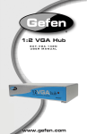
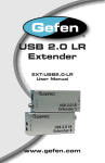
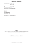
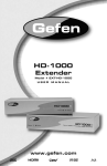
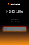
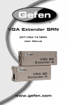
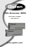
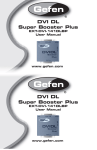
*Preferred
DVI Detective
EXT-DVI-EDIDN
User Manual
Release A3
Important Safety Instructions
1.
Read these instructions.
2.
Keep these instructions.
3.
Heed all warnings.
4.
Follow all instructions.
5.
Do not use this product near water.
6.
Clean only with a dry cloth.
7.
Do not block any ventilation openings. Install in accordance with the manufacturer’s
instructions.
8.
Do not install or place this product near any heat sources such as radiators, heat
registers, stoves, or other apparatus (including amplifiers) that produce heat.
9.
Do not defeat the safety purpose of the polarized or grounding-type plug. A polarized
plug has two blades with one wider than the other. A grounding type plug has two
blades and a third grounding prong. The wide blade or the third prong are provided for
your safety. If the provided plug does not fit into your outlet, consult an electrician for
replacement of the obsolete outlet.
10. Protect the power cord from being walked on or pinched particularly at plugs,
convenience receptacles, and the point where they exit from the apparatus.
11. Only use attachments/accessories specified by the manufacturer.
12. To reduce the risk of electric shock and/or damage to this product, never handle or
touch this unit or power cord if your hands are wet or damp. Do not expose this
product to rain or moisture.
13. Unplug this apparatus during lightning storms or when unused for long periods of time.
14. Refer all servicing to qualified service personnel. Servicing is required when the
apparatus has been damaged in any way, such as power-supply cord or plug is
damaged, liquid has been spilled or objects have fallen into the apparatus,
the apparatus has been exposed to rain or moisture, does not operate normally,
or has been dropped.
15. Batteries that may be included with this product and/or accessories should never be
exposed to open flame or excessive heat. Always dispose of used batteries
according to the instructions.
ii
Warranty Information
Gefen warrants the equipment it manufactures to be free from defects in material and
workmanship.
If equipment fails because of such defects and Gefen is notified within two (2) years from
the date of shipment, Gefen will, at its option, repair or replace the equipment, provided
that the equipment has not been subjected to mechanical, electrical, or other abuse or
modifications. Equipment that fails under conditions other than those covered will be
repaired at the current price of parts and labor in effect at the time of repair. Such repairs
are warranted for ninety (90) days from the day of reshipment to the Buyer.
This warranty is in lieu of all other warranties expressed or implied, including without
limitation, any implied warranty or merchantability or fitness for any particular purpose, all of
which are expressly disclaimed.
1.
Proof of sale may be required in order to claim warranty.
2.
Customers outside the US are responsible for shipping charges to and from Gefen.
3.
Copper cables are limited to a 30 day warranty and cables must be in their original
condition.
The information in this manual has been carefully checked and is believed to be accurate.
However, Gefen assumes no responsibility for any inaccuracies that may be contained
in this manual. In no event will Gefen be liable for direct, indirect, special, incidental, or
consequential damages resulting from any defect or omission in this manual, even if
advised of the possibility of such damages. The technical information contained herein
regarding the features and specifications is subject to change without notice.
For the latest warranty coverage information, refer to the Warranty and Return Policy under
the Support section of the Gefen Web site at www.gefen.com.
iii
Contacting Gefen Technical Support
Technical Support
(818) 772-9100
(800) 545-6900
8:00 AM to 5:00 PM Monday - Friday, Pacific Time
Fax
(818) 772-9120
Email
[email protected]
Web
http://www.gefen.com
Mailing Address
Gefen, LLC
c/o Customer Service
20600 Nordhoff St.
Chatsworth, CA 91311
Product Registration
Register your product here: http://www.gefen.com/kvm/Registry/Registration.jsp
iv
Operating Notes
This page left intentionally blank.
DVI Detective is a trademark of Gefen, LLC.
© 2015 Gefen, LLC. All Rights Reserved. All trademarks are the property of their respective owners.
Gefen, LLC reserves the right to make changes in the hardware, packaging, and any accompanying documentation
without prior written notice.
Pb
This product uses UL or CE listed power supplies.
v
Features and Packing List
Features
•
Quick and easy way to store EDID information from any DVI display
•
Provides a virtual EDID to maintain active monitor status when switching away from a
source
•
Supports resolutions up to 1920x1200, 2K, and 3840x2400 (Dual Link)
•
EDID write protection switch
•
No power is required after initial programming
Packing List
The following items are shipped with the DVI Detective. If any of these items are not
present in the box when you first open it, immediately contact your dealer or Gefen.
•
•
•
•
1 x DVI Detective
1 x 1 ft. Dual-Link DVI Cable (M-M)
1 x 5V DC Power Supply
1 x Quick-Start Guide
vi
Table of Contents
1
Getting Started
Introduction............................................................................................................ 2
Installation.............................................................................................................. 4
Connecting the DVI Detective........................................................................ 4
Sample Wiring Diagram................................................................................. 4
2
Basic Operation
EDID Programming................................................................................................ 8
LED Status............................................................................................................. 9
3Appendix
Specifications....................................................................................................... 12
viii
DVI Detective
1
Getting Started
Introduction............................................................................................................ 2
Installation.............................................................................................................. 4
Connecting the DVI Detective........................................................................ 4
Sample Wiring Diagram................................................................................. 4
Detective
Prog
Getting Started
Introduction
DVI In
Power
1
2
EXT-DVI-EDIDN
WR
E D
DVI Out
5V DC
DVI
Detective
Prog
DVI In
Power
3
4
5
EXT-DVI-EDIDN
WR
E D
DVI Out
page | 2
Getting Started
Introduction
ID
Name
Description
1
DVI Out
Connect the DVI display to this port using a
DVI cable.
2
WR
Write-enable switch. Flip this switch to the
“E” position to allow the DVI Detective to
be programmed with an (external) EDID.
Set this switch to the “D” position to disable
programming and prevent an accidental
erasure of the current EDID.
3
Prog
Press this button to begin programming an
EDID. See EDID Programming (page 8)
for more information.
4
DVI In
Connect the DVI source to this port using the
included DVI cable.
5
Power
This LED will glow bright red when the unit is
powered.
page | 3
Installation
Getting Started
Connecting the DVI Detective
Stop!
Before connecting the DVI Detective, the unit must be programmed with an
EDID. See EDID Programming (page 8) for more information, before
continuing with the installation.
1.
Connect the included DVI cable from the DVI source to the DVI In port on the
DVI Detective.
2.
Use another DVI cable to connect the display (or other sink) to the DVI Out
port on the detective.
3.
Power-on the display (sink) device and the source. The included 5V DC power
supply is not required.
Sample Wiring Diagram
DVI CABLE
Computer
DVI Detective N
Monitor
EXT-DVI-EDIDN
page | 4
DVI Detective
2
Basic Operation
EDID Programming................................................................................................ 8
LED Status............................................................................................................. 9
page | 7
Before using the DVI Detective, the unit must be programmed with an EDID. In most
cases, the DVI Detective should be programmed with the EDID of the display (or other sink
device) to which you are connecting the source. Once programmed, the EDID data will be
read by the source, providing all the necessary details of the type of signal that the display
(or other sink device) can process. Although any DVI Detective can be programmed with
any EDID, the display (or other sink device) must be able to support those features.
5V DC
Basic Operation
EDID Programming
DVI
Detective
1.
Begin by powering-on
sink device) containing
the EDID
Prog the display (or other
DVI In
Power
to be recorded.
2.
Connect a DVI cable from the sink device to the DVI Out port on the DVI Detective.
3.
Move the WR switch to the “E” position in order to allow the EDID to be written
to the DVI Detective.
Write-enabled
EXT-DVI-EDIDN
WR
E D
DVI Out
4.
Connect the included 5V DC power supply to the DVI Detective. The Power LED,
on the other side of the unit, will glow solid red.
5.
Press and release the Prog button. The Power LED will flash as the EDID
is recorded.
Prog button
6.
Once the EDID has been recorded, the Power LED will glow bright red.
7.
Move the WR switch to the “D” position to prevent accidental erasure of the EDID.
8.
The EDID programming process is complete.
9.
See Connecting the DVI Detective (page 4).
page | 8
5V
Basic Operation
LED Status
The Power Link LED indicator on the DVI Detective provides basic information on the
current status.
Status
Description
Solid red
•
The 5V DC power supply is connected to the
DVI Detective.
•
The DVI Detective is connected between the
source device and the display (sink) device.
•
The DVI Detective is being programmed with
an EDID.
Flashes red
DVI Detective
3Appendix
Specifications....................................................................................................... 12
Appendix
Specifications
Supported Formats
Video
•
•
•
3840 x 2400 (Dual-link)
2048 x 1080 (2K)
1920 x 1200 (WUXGA)
Connectors, Controls, and Indicators
DVI In
•
1 x DVI-I, 29-pin, female
DVI Out
•
1 x DVI-I, 29-pin, female
Programming
•
1 x Push button, momentary switch
Write-protect switch
•
1 x two-position, slide switch
Power
•
1 x LED, red
Maximum Pixel Clock
•
2 x 165 MHz
Power Input
•
5V DC
Power Consumption
•
5 Watts (max.)
Operating Temperature
•
+41 to +113 °F (+5 to +45 °C)
Dimensions (W x H x D)
•
2.6” x 1.8” x 1.2”
(66mm x 46mm x 30mm)
Unit Weight
•
0.18 lbs (0.08 kg)
Operational
Physical
page | 12
*Preferred
Stretch it. Switch it. Split it. Gefen’s got it. ®
20600 Nordhoff St., Chatsworth CA 91311
1-800-545-6900 818-772-9100 fax: 818-772-9120
www.gefen.com [email protected]