1
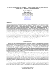
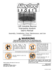
User Manual MIAMI UNIVERSITY Mechanical Engineering Vibrations Laboratory User Manual for Small Scale Road Vibration Experimental Setup MIAMI UNIVERSITY VIBRATIONS LABORATORY User Manual for Small Scale Road Vibration Experimental Setup Miami University School of Engineering and Applied Science Department of Mechanical and Manufacturing Engineering 144 Kreger Hall Oxford, OH 45056 U S E R M A N U A L F O R S M A L L E X P E R I M E N T A L S E T U P S C A L E R A O D V I B R A T I O N User Manual for Small Scale Road Vibration Experimental Setup Equipment • MB Dynamics Modal 50A electrodynamic shaker • Amplifier • Amplifier connection cord • Shaker Accessories o Tool kit o Cooling system o Stinger 1 User Manual U S E R M A N U A L F O R S M A L L E X P E R I M E N T A L S E T U P S C A L E • Alro Racing TKTjunior 1/5th scale car • Support Structure R A O D V I B R A T I O N o 4 bungee cords • 4 Accelerometers (varying sizes) • 4 Accelerometer connecting cords (black for small accelerometers, white for larger accelerometers) • Glue gun and sticks • Computer running GUI 2 U S E R M A N U A L F O R S M A L L E X P E R I M E N T A L S E T U P S C A L E • Laptop running Signal Calc Ace • DAQ software • Signal conditioning board Overall Experimental Setup 3 R A O D V I B R A T I O N U S E R M A N U A L F O R S M A L L E X P E R I M E N T A L S E T U P S C A L E R A O D V I B R A T I O N Safety For in depth information on the shaker (accessories included) and car, please refer to the owner’s manuals supplied by companies. The following is a general list of information for basic use of the experimental setup. Following this list will allow the user to maintain safe operation and the integrity of the equipment. If unsure about any of the following procedures or locations, please ask instructor for clarification. • Do not touch the cords on the back of the amplifier • Make sure to use two wrenches to tighten and loosen stinger o Hold the bottom nut stationary and turn the top nut to tighten or loosen • Make sure amplifier is off before starting signal calc ace hardware; after this, slowly increase amplitude • Do not turn up the amplifier more than halfway without use of cooling system • Make sure to use hot glue to safely secure the stinger to a flat part of the car • Car is heavy; do not disconnect bungee cords without securing car first • Beware of sharp edges on support structure • Make sure car is level when attached to stinger • Make sure accelerometers are attached using wax at a perpendicular direction • Make sure the signal conditioning board has all settings set to “DIFF” and “ON” Experimental Setup The following is the setup procedure for the experimental setup. 1. Attach car to support structure a. Supporting the car’s weight, attach the bungee cords to each of the four aluminum “C” brackets on the car 4 U S E R M A N U A L F O R S M A L L E X P E R I M E N T A L S E T U P S C A L E R A O D V I B R A T I O N b. Making sure the car’s front is facing the support structure leg labeled “F”, attach the bungee cords from the car to the corresponding holes in the structure labeled with “x’s” c. Make sure the car is hanging level, if not make necessary adjustments 2. Attach amplifier to shaker a. Make sure to follow safety considerations. Note: Do not touch the back of the amplifier when it is turned on b. Plug in amplifier to power supply c. Making sure amplifier is turned off, plug amplifier into shaker d. Locate the cable coming from the laptop that has four colored coax cables on one end and the laptop serial connection on the other e. Connect the serial end to the port located on the right side of the laptop f. Connect white tipped cord (of the four colored coax cables) from laptop to top coax input labeled “AC” located on the back of the amplifier 3. Attach cooling system to shaker (if needed) a. Plug cooling vacuum into power supply b. Attach vacuum hose to shaker 4. Attach input measuring accelerometer to car a. Attach cord to a accelerometer Note: White cords are for the larger accelerometers and the black cords are for the smaller accelerometers b. Plug cord into channel zero on the signal conditioning board in the “Analog input” portion of the board c. Put wax on accelerometer d. Attach accelerometer directly above stinger position on car 5 U S E R M A N U A L F O R S M A L L E X P E R I M E N T A L S E T U P S C A L E R A O D V I B R A T I O N Note: Make sure the accelerometer is attached with wax in a perpendicular direction to the surface of the car 5. Attach output measuring accelerometer to car a. Attach cord(s) to accelerometer(s) b. Plug cord(s) into channels 1-3 on the signal conditioning board in the “Analog input” portion of the board c. Put wax on accelerometer(s) d. Attach accelerometer(s) to car according to lab requirements making sure accelerometer is perpendicular to surface Note: Make sure the accelerometer is attached with wax in a perpendicular direction to the surface of the car 6. Attach shaker to car a. Make sure to follow safety considerations b. Plug shaker into power supply c. Get stinger from inside tool kit. d. Place stinger in brass chuck located on the top of the shaker e. Using two wrenches (from the tool box), hold the bottom nut stationary and turn the top nut to tighten at appropriate height f. Using hot glue gun, add a drop of glue to the stinger end and attach to the flat part of the bottom of the car underneath the label “:S” Note: When gluing the stinger to the car, press and hold to ensure that the stinger is in complete contact with the flat part of the car’s chassis 7. Make sure signal conditioning board is set correctly a. Power is “on” b. All settings are set at “on” and “diff” 6 U S E R M A N U A L F O R S M A L L E X P E R I M E N T A L S E T U P S C A L E R A O D V I B R A T I O N Zoom Capability When the GUI is run, a mini ‘Zoom’ pop-up menu will be displayed in the corner of the GUI transfer function graph. This pop-up menu can be used to zoom in and out of the GUI graphs. Zoom Pop-up Menu In order to zoom in, click on the ‘in’ button of the pop-up menu. Use the mouse and click on the desired locations for the lower left and upper right corners, respectively, of the plot that is to be generated. In order to zoom out, click on the ‘out’ button of the pop-up menu. The graph will automatically zoom out to an appropriately expanded set of axes. Note: The home and quit buttons of the ‘Zoom’ pop-up should NOT be used. The ‘home’ button will zoom the graph into a predefined set of axes which are NOT relevant to this experiment. The ‘quit’ button will remove the pop-up menu from the screen, eliminating the zoom capability until the GUI is run again. 7 U S E R M A N U A L F O R S M A L L E X P E R I M E N T A L S E T U P S C A L E R A O D V I B R A T I O N Dismantling Experiment 8. First turn the power off on amplifier 9. Disconnect the amplifier from the shaker 10. Disconnect accelerometers from car’s body 11. Disconnect cords from accelerometers and put cords and accelerometers where found 12. Carefully detach stinger from car 13. Take the stinger out of the shaker using two wrenches to loosen 14. If necessary, disconnect the car from the support structure making sure to support the car at all times 15. If necessary, disconnect the cooling system from the shaker 8 9