1
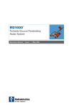
Model 5100 Antenna
System Settings and User Notes
The Difference is the Data
Geophysical Survey Systems, Inc.
13 Klein Drive, P.O. Box 97
North Salem, NH 03073-0097
Phone: (603) 893-1109 / FAX: (603) 889-3984
www.geophysical.com
sales@geophysical.
Manual MN31-079 Rev C
Geophysical Survey Systems, Inc.
Model 5100 Antenna
System Settings and User Notes
Limited Warranty, Limitations Of Liability And Restrictions
Geophysical Survey Systems, Inc. hereinafter referred to as GSSI, warrants that, for a period of
24 months from the delivery date to the original purchaser, GSSI's products will be free from
defects in materials and workmanship. EXCEPT FOR THE FOREGOING LIMITED
WARRANTY, GSSI DISCLAIMS ALL WARRANTIES, EXPRESS OR IMPLIED,
INCLUDING ANY WARRANTY OF MERCHANTABILITY OR FITNESS FOR A
PARTICULAR PURPOSE. GSSI's obligation is limited to repairing or replacing parts or
equipment which are returned to GSSI, transportation and insurance pre-paid, without alteration
or further damage, and which in GSSI's judgment, were defective or became defective during
normal use.
GSSI ASSUMES NO LIABILITY FOR ANY DIRECT, INDIRECT, SPECIAL, INCIDENTAL
OR CONSEQUENTIAL DAMAGES OR INJURIES CAUSED BY PROPER OR IMPROPER
OPERATION OF ITS EQUIPMENT OR SOFTWARE, WHETHER OR NOT DEFECTIVE.
Before returning any equipment to GSSI, a Return Material Authorization (RMA) number must
be obtained. Please call the GSSI Customer Service Manager who will assign an RMA number.
Be sure to have the serial number of the unit available.
GSSI does not convey any license under its patent or other intellectual property rights or the
rights of others.
Note: Information in this manual is subject to change without notice. Please consult the
manual updates supplied with your system and contact GSSI with any additional
questions.
Copyright© 2003, 2005 Geophysical Survey Systems, Inc.
All rights reserved
including the right of reproduction
in whole or in part in any form
Published by Geophysical Survey Systems, Inc.
13 Klein Drive
North Salem, New Hampshire 03073-0097
Printed in the United States
GSSI and SIR are registered trademarks of
Geophysical Survey Systems, Inc.
Manual MN31-079 Rev C
Geophysical Survey Systems, Inc.
Model 5100 Antenna
System Settings and User Notes
FCC Notice (for U.S. Customers):
This device complies with part 15 of the FCC Rules:
Operation is subject to the following conditions:
1. This device many not cause harmful interference, and
2. This device must accept any interference received, Including interference that may cause
undesired operation
Warning:
Changes or modifications to this unit not expressly approved by the party responsible for
compliance could void the user’s authority to operate the equipment.
Operation of this device is restricted to law enforcement, fire and rescue officials,
scientific research institutes, commercial mining companies, and construction
companies. Operation by any other party is a violation of 47 U.S.C. § 301 and could
subject the operator to serious legal penalties.
Coordination Requirements.
(a) UWB imaging systems require coordination through the FCC before the equipment may
be used. The operator shall comply with any constraints on equipment usage resulting from this
coordination.
(b) The users of UWB imaging devices shall supply detailed operational areas to the FCC
Office of Engineering and Technology who shall coordinate this information with the Federal
Government through the National Telecommunications and Information Administration. The
information provided by the UWB operator shall include the name, address and other pertinent
contact information of the user, the desired geographical area of operation, and the FCC ID number
and other nomenclature of the UWB device. This material shall be submitted to the following
address:
Frequency Coordination Branch., OET
Federal Communications Commission
445 12th Street, SW
Washington, D.C. 20554
ATTN: UWB Coordination
(d) Users of authorized, coordinated UWB systems may transfer them to other qualified
users and to different locations upon coordination of change of ownership or location to the FCC and
coordination with existing authorized operations.
(e) The NTIA/FCC coordination report shall include any needed constraints that apply to
day-to-day operations. Such constraints could specify prohibited areas of operations or areas
located near authorized radio stations for which additional coordination is required before operation
of the UWB equipment. If additional local coordination is required, a local coordination contact will be
provided.
(f) The coordination of routine UWB operations shall not take longer than 15 business days
from the receipt of the coordination request by NTIA. Special temporary operations may be handled
with an expedited turn-around time when circumstances warrant. The operation of UWB systems in
emergency situations involving the safety of life or property may occur without coordination provided
a notification procedure, similar to that contained in CFR47 Section 2.405(a)-(e), is followed by the
UWB equipment user.
NOTICE: Use of this device as a wall imaging system is prohibited by FCC regulations.
Manual MN31-079 Rev C
Geophysical Survey Systems, Inc.
Model 5100 Antenna
System Settings and User Notes
Model 5100 Antenna
The Model 5100 antenna has greatly improved performance over previous high frequency
antennas. Not only is the frequency higher, but the antenna has the ability to see objects at very
close distances.
System Setup - Standard Settings
Note: These setup instructions will allow you to properly use the Model 5100 antenna.
Setup Mode: Manual
System Run Mode: Distance/Survey Wheel (recommended) or Continuous
Range: 6-20 ns
Number of Gain Points: 3-5
Vertical Low Pass Filter: 3000 MHz
Vertical High Pass Filter: 250 MHz
Vertical High Pass (IIR): 10 MHz
Samples per Scan: 512
Bits per Sample: 16
Scans per Second: Set to the maximum scan rate allowed by the SIR System used
Signal Position
Place the antenna on the
concrete floor and use the
Automatic Signal Position
selection. You may need to
try this 2 to 3 times to get
the system to lock on to the
surface pulse. If after 3
tries, the surface pulse is
not in the signal window,
point the antenna into the
air and again try the
Automatic Position.
To test that you have the
correct position, raise the
antenna off the ground and
you will observe on your system that the antenna transmit pulse will separate from the reflection
from the ground. The higher that you raise the antenna, the further apart will be the two pulses.
Manual MN31-079 Rev C
1
Geophysical Survey Systems, Inc.
Model 5100 Antenna
System Settings and User Notes
Gain Check
The surface pulse should be about 2/3 the width of the screen. If it is
greater, reduce the Gains manually. If the signal appears too small, you
can manually increase the Gains, but the first gain point should never
exceed 10dB.
Minicart
Your Model 5100 is designed to fit into the Model 615 minicart. Using the
antenna with the minicart allows you to take advantage of distance-based
data collection which is possible with a survey wheel. A survey wheel (rear-axle of the cart)
tracks the distance traveled and allows consistent scan spacing. The minicart is available as a
separate purchase and is also compatible with the Model 5101 antenna. Please contact your GSSI
sales representative for details.
Note: The Model 5100 is not intended for use as a wall or ceiling imaging device.
Manual MN31-079 Rev C
2
Geophysical Survey Systems, Inc.
Model 5100 Antenna
System Settings and User Notes
Data Collection
Collecting Data Using The Survey Wheel With The Standard Settings
System Run Mode: Survey Wheel
Number of Scans per Meter: 80 (24 scans per foot) or higher. GSSI StructureScan
concrete imaging systems collect 60 scans/foot or higher.
Remote Operation
This may differ depending on your control unit. See your control unit’s user manual for details.
•
Pressing the thumb marker switch on the 615 cart for less than one second will place a
marker in the data.
•
To put the system into Standby mode during data acquisition, press the button for more
than two seconds, but less than six seconds, then release the button.
•
Pressing the button for longer than 6 seconds will close any open files and turn off the
transmitter. To resume, the data acquisition sequence must be repeated.
Special Settings Used For Collecting Data On Bridge Decks
Setup Mode: Manual
System Run Mode: Survey Wheel
Range: 6 ns (unpaved), 10 ns (paved)
Number of Gain Points: 1
Vertical Low Pass Filter: 3000 MHz
Vertical High Pass Filter: 250 MHz
No Horizontal Filters
Samples per Scan: 512
Bits per Sample: 16
Scans per Second: Set to the maximum scan rate allowed by the SIR System used
Signal Positioning: Use the same procedure as in standard setup
Set the Scans per Meter parameter to 80 scans per meter (24 scans per foot)
Calibrate the survey wheel before collecting data
Note: See Bridge Assessment Manual before proceeding.
Specifications
Center frequency: 1600 MHz
Pulse duration: 0.7 ns
Size of sensor: 1.5 x 4 x 6.5 inches (3.8 x 10 x 16.5 cm)
Depth of penetration: 0-18“ depending on type of concrete
Model 615 Survey Cart:
Manual MN31-079 Rev C
3
1229 ticks/foot
4030 ticks/meter