1
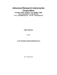
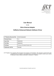
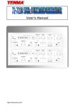
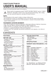
Advanced Research Instruments
Corporation
11950 Spruce Canyon Circle, Golden, CO 80403, USA
Phone (303)463-5500 Fax (303)463-5505
Email: [email protected] Web Site: www.aricorp.com
USER MANUAL
for the
MTS-100 PREAMPLIFIER/DISCRIMINATOR
March 2000
TABLE OF CONTENTS
MTS-100 SPECIFICIATIONS
INTRODUCTION
Figure 1. Detailed H.V. Biasing Diagram of MTS-100
INSTALLATION
Output Consideration
Pulse Width
Figure 2. Timing Capacitor Selection for Desired Ouput
Pulse Width
Figure 3. Connector Pin-Out
Figure 4. Cable Selection Guide
Figure 5. Cable Diagram
Potential Problems
Figure 6. Example of Ringing Reduction by 50 Ohm
Termination (Horizontal 100ns, Vertical 1V/div)
Input Considerations
OPERATION
Connecting and Disconnecting Your Preamplifier
Discriminator Set Up
Figure 7. Typical Signal from the Detector and Threshold
Setting.
Figure 8. Relationship Between Threshold Position and
resulting Count Rate
TROBLE-SHOOTING GUIDE
No Output Pulses
Too Much Noise
Figure 9. Missing Ground in the SHV Connector
Double Pulsing
Reducing Power Supply Induced Noise
Using a Suitable Power Supply to Reduce Noise
Noise from the Positive H.V. Supply
Noise Reduction by Negative H.V. Biasing Technique
Positive H.V. Biasing
PHOTON COUNTING APPLICATIONS
How to Optimize Photon Counting
How To Minimize the Background Count
Maximizing the Useful Count Rate
How to Automate Your Data Acquisition
1
2
3
3
5
5
5
5
6
6
7
8
9
9
11
11
11
11
11
13
13
13
14
15
16
16
16
16
17
18
18
18
19
19
MTS-100 SPECIFICATIONS
Input impedance
Input range
Input charge sensitivity
Linear section gain
Noise referred to input
Input pulse polarity
Input over voltage protection
Input connector
Threshold adjustment range
Maximum pulse repetition rate
Pulse pair resolution
Minimum output pulse width
Maximum output pulse width
Output signal
Output impedance
Power connector and signal
Second Output Signal
Power requirements
Physical size
Maximum H.V. Bias
2
50Ω
160µV to 200mV
<70 fC
60db
<5µV RMS
Negative
Standard
SHV
100µV to 2.5mV (ref. to input)
>50MHz
<20ns
10ns (standard)
1µs
+5V (TTL)
50Ω
9 pin mini D type
BNC
"8V to "24VDC/50mA
1.7” x 2.4” x 7.2”
5kV
USER MANUAL
for the
MTS-100 PREAMPLIFIER/DISCRIMINATOR V7
INTRODUCTION
The MTS-100 Preamplifier amplifies minute pulses from Photomultiplier tubes, Electron
multipliers and similar detectors, to produce standard TTL pulses for counting applications.
The MTS-100 also includes a decoupling H.V. network necessary to fulfill the detector bias
requirements. It features a low pass filter in the H.V. path to lower any noise there may be
on the H.V. line. The filter is especially crucial when the positive H.V. biasing scheme is
used.
Fig. 1 Detailed H.V. Biasing Diagram of MTS-100.
The H.V. bias illustrated in Figure 1 requires positive High Voltage for the detector to have
its collector at a more positive potential than the front of the electron multiplier.
This biasing scheme has several advantages over a negative biasing scheme.
Since the detectors entrance is close to the ground potenitial and it’s not committed, it may
be biased up to several hundred volts negative by an additional supply, to attract positive
ions or other positively charged particles. By changing the polarity of such additional bias
supply, we simply switch the system to detect negatively charged particles. However,
when using such an additional bias, we must remember to change the detector’s bias
accordingly since both supplies are typically grounded (referenced to ground).
When using a floating (uncommitted) high voltage supply for the detector, switching from
positive to negative particle detection is much simpler. All we have to do is change the
entrance bias. Although in this case we don’t have to worry about the influence on the
3
potential across the detector, it is absolutely necessary to shut the supplies off before
changing the polarity of the bias supply.
A low bias potential at the entrance also creates a low electrostatic field that is less likely to
attract a variety of possible spurious charged particles generated by a field emission,
thermal emission or photo emission and contribute to the background count rate. This
becomes particularly important when operating at low intensities where the background is
highly significant.
The positive biasing scheme however has one disadvantage. The noise (ripple) from the
H.V. supply is directly coupled to the preamplifier which determines the lowest detection
limit for the signal. It should be obvious that if the ripple is specified as 10mV peak to peak
value, we cannot expect to detect any pulses smaller than that unless we want to count the
H.V. ripple also.
Caution: Some H.V. supply manufacturers specify the ripple as an RMS value which may
be 5-10 times smaller than the peak to peak value of the same ripple. Since most of the
H.V. supplies today are the switching regulator type, the noise consists mostly of high
narrow shape pulses yielding a rather low RMS value. It seems to be more attractive to
specify a low noise level in RMS value than a much higher one in the peak to peak value.
A good indication of whether or not the H.V. supply we are using is too noisy is the specific
rate meter reading (the switching frequency of the supply) without signal present, with the
H.V. on and the threshold of the noise discriminator safely above the amplifier – detector
noise level. Although the H.V. always increases the background count rate, when the rate
meter reads a stable frequency between 20kHz and 200kHz (or Counts Per Second CPS),
it is a definite indication that we are counting the H.V. ripple frequency.
The RC filter in Figure 1 consisting of R3 and C2 will reduce the H.V. noise level
significantly, but it will not eliminate it. For the best results, the lowest possible noise-ripple
H.V. supply is absolutely essential.
The preamplifier follows the decoupling network and its function and operation are
described in the next part of this manual.
4
USER MANUAL
for the
MTS-100 PREAMPLIFIER/DISCRIMINATOR V7
This manual is written to assist you in the installation and operation of your MTS-100
preamplifier/discriminator.
INSTALLATION
Refer to Figure 3 on the following page for the connector pin-out.
The preamplifier requires an unregulated dual power supply of "8V to "24V: typically "12V, "15V
or "24V at +50mA and -30mA. This is the least critical connection, since built-in voltage regulators
virtually eliminate any ripple, instability, or noise on the power lines.
Output Considerations
Output pulses from pin 1 represent the standard TTL/CMOS level: +5.0V unterminated with respect
to ground (pin 6).
The output impedance of the MTS-100 is 50 ohms. To avoid any potential problems related to an
improperly terminated transmission line such as ringing or multiple pulsing, use a 50Ω coaxial cable
terminated by a 50Ω resistor or a ratemeter with 50Ω input impedance.
Pulse Width
The minimum output pulse width is about 10ns. You can extend the pulse width by adding a C8T
capacitor inside the MTS-100. The graph in Figure 2 enables you to determine the required
capacitor corresponding to the desired pulse width. However, it is important to use the minimum
pulse width that can be tolerated by the rate meter. This is because the minimum pulse pair spacing
(maximum pulse pair resolution) is directly related to the output pulse width, and pulse pair
resolution is limited by the output pulse width. Therefore, the wider the output pulse width, the
worse will be the pulse pair resolution, and the lower the maximum count rate.
10000
Capacitance [pF]
1000
100
10
1
10
100
1000
P u ls e W id t h [ n s ]
Figure 2. Timing Capacitor Selection for Desired Output Pulse Width
5
Pin Number –
Signal
1
TTL Output
2
Not Used
3
V + (+8 to +24 VDC)
4
Not Used
5
Not Used
6
Signal Ground
7
Power Supply Ground
8
V - (-8 to -24VDC)
9
Optional remote threshold control/monitor
Figure 3. Power connector pin-Out.
Figure 4. Cable Selection Guide
6
Figure 5. Cable Diagrams
7
Potential Problems
Two potential problems may be associated with the 50Ω termination. These are discussed as
follows:
!
Some rate-meters or counters may have only a high impedance input available, therefore an
external terminator must be used.
If your rate meter does not have 50 Ω input impedance, you can easily modify it by attaching
a metal film or carbon resistor across the input. Do not use wire-wound resistors because
they tend to have high inductance. If modifying the input is not feasible, a BNC "tee" adaptor
may be used with a BNC 50 Ω terminator. The 50 Ω terminators are available from
Advanced Research Instruments Corp. or any major electronic supplier.
!
The 50Ω terminator reduces the pulse height to +3.0V, which may not be sufficient for some
rate meters to detect.
If the +3.0V pulse height is insufficient for your rate meter or counter, you might consider an
unterminated signal connection; but only if the physical length of the coax cable is less than
approximately one meter. The shorter the connection, the safer it is to use the unterminated
cable.
The decision as to whether to use a terminated cable must be based on the input
specifications of the your counter/timer/rate meter. A fast, sensitive rate meter (>20 MHz,
with sensitivity <1V) always requires proper termination. A relatively slow rate meter usually
has an input sensitivity control or a threshold adjustment that can be used for input signals of
.1V to 25V and high input impedance. In this case, although external termination for a short
cable may not be absolutely necessary, it is nevertheless recommended. The 3.0V signal
level, with a properly adjusted input threshold to about 1V is the best solution. A long cable
longer than 15 feet (>5 meters) must almost always be terminated.
The following examples (Figures 6a and 6b) show significant improvement of reflectance, for
a terminated cable compared with an unterminated one.
The most significant value is the positive excursion of the ringing value, since the tripping threshold
for the TTL signals is about +0.7V minimum. The +1.0V glitch on the unterminated cable will very
likely produce a double pulsing.
The problem is most severe when a high frequency and high sensitivity counter is used. When
selecting the counter/timer/rate meter, make sure that only the signal pulses are being counted.
Measurements on a shorter cable indicate only minor ringing amplitude. So it is possible to use
even unterminated cables, but only if an input threshold is, or can be adjusted safely above the
ringing level.
Or, you could use high-threshold integrated circuits such as 7414, 74LS14, 74S14, 74HC series,
etc., on the input of your counter/timer or rate meter.
8
0V
0V
Figure 6a. 16 feet of unterminated 50 Ω cable.
Note the +1.0V glitch that may be detected by
the counter as a second pulse.
Figure 6b. The same 16 foot 50Ω terminated
cable. Note the absence of glitches but the
pulse height is reduced to 2.8V.
Figure 6. Example of Ringing Reduction by 50Ω Termination
(Horizontal: 25 ns; Vertical: 1V/div)
To conclude, most TTL signals do not need termination unless long coaxial cables are involved. If
you terminate the cable, ringing is reduced significantly; unfortunately, the signal is thereby reduced
to about half its original amplitude. If this is a problem, an intermediate solution may be the answer.
A 100Ω terminator on a 50Ω cable produces only slightly larger ringing than a 50 Ω terminator, but
the pulse amplitude is only slightly less than the original.
Input Considerations
The input connection is far more critical than the output connection. High sensitivity input requires
the shortest possible connection to the PMT or to an electron multiplier. Also, the noise in the input
signal or in the input ground connection must be eliminated by setting the discriminator to a lower
sensitivity region, thus reducing the overall performance.
Bear in mind that the 160 µV input sensitivity of the MTS-100 preamplifier is about the same as most
radio and television receivers, except with a much larger bandwidth (making the situation much
more critical). Also the preamplifier must operate in an electrically hostile environment without
responding to the severe interference of switching power supplies, the R.F. part of mass
spectrometers, computers, SCRs, etc.
These interference sources are a serious threat to an interference-free operation of the preamplifier,
especially if they are located in the vicinity of the detector/preamplifier. Therefore, good R.F.
grounding and shielding rules must be strictly observed.
Preamplifiers are normally set to accept negative pulses since all PMTs and electron multipliers
9
produce such pulses. Although the input of the MTS-100 is compatible with either a positive or a
negative biasing scheme of the PMT, the details may vary substantially.
Finally, for the input connection itself, use a SHV-to-SHV adaptor or a very short cable. Under some
circumstances an additional ground strap may be necessary.
10
OPERATION
Connecting and Disconnecting Your Preamplifier
CAUTION
Before applying power, recheck the low voltage polarity.
Reversed +V with -V may destroy the preamplifier!
Although the input to the MTS-100 is protected against high voltage spikes, do not connect or
disconnect the input with high voltage bias applied to the detector. Use the following procedure to
ensure virtually trouble-free performance in your preamplifier:
!
To connect the preamplifier to the detector, first make the connection, then turn on the high
voltage.
!
To disconnect the preamplifier from the detector, first turn off the high voltage, then wait 5-10
seconds. Then you may safely disconnect the preamplifier.
Discriminator Set Up
The discriminator is factory set to the position that works well for the Advanced Research
Instruments PMT test system.
However, this setting may need to be changed for different systems and different bias settings.
Consider Figures 7 and 8.
+ 1V
CW
“T h re s h o ld t o o h ig h ” re g io n .
M is s in g m o s t o f th e s ig n a l.
T o p o f th e
s ig n a l p u ls e s .
T h re s h o ld .
B e s t S e t tin g
P ea k to
p e a k n o is e
le v e l.
N o is e re g io n
0V
0n s
T im e
50 ns
C ou n t r ate
T rue C ou nt
ra t e
O u t p u t f ro m th e C o m p a r a t o r
TTL
Figure 8. Relationship between the
threshold position and resulting count
rate
Figure 7. Typical signal from the
detector and the threshold setting. The
output from the comparator and the
final TTL output from the MTS-100.
11
Figure 7 shows signal and noise coming from the linear preamplifier just before it enters the
discriminator for thresholding. When the threshold trimmer is turned fully counterclockwise, the
threshold is buried in noise (input noise plus preamplifier noise), and the MTS-100 produces high
count rate pulses even if no signal is present (see Figure 8).
Note the count rate when the threshold is set close to zero. Since this is an unacceptable situation,
the solution is to increase the threshold by turning the trimmer clockwise until the noise disappears:
!
Perform this adjustment with the MTS-100 connected to the detector and the rate meter.
!
Be sure that when you perform the adjustment that power is applied to the MTS-100, but
without the high voltage applied to the detector.
Note: If there are no pulses, even with the discriminator fully counterclockwise, the
noise level might be below the minimum detectable threshold, or additional
problems may be present.
With the signal source (photons, electrons, etc.) turned off, turn on the high voltage and slowly
increase to the approximate operating range. (If no H.V. adjustment is feasible, then just turn it on).
Noise should increase because the bias background is significantly higher than the noise of the
preamplifier. Increase (turning clockwise) the threshold above the noise level. A count rate of 1 to 5
cps may be acceptable. The background count rate is usually determined by the quality of the
detector or the entire experimental set-up.
Now apply the signal to your detector (PMT or electron multiplier). The count rate should increase to
the correct level.
With the signal applied, increase the threshold by turning the threshold trimmer further clockwise,
and note the change in the count rate. There should be minimal change within certain ranges. i.e.,
the "best setting," as shown in Figure 8. When you reach a threshold setting that is too high, the
count rate drastically drops off. The best setting is approximately in the middle between the noise
level and loss of the signal.
If you cannot locate the point of losing the signal, this indicates unnecessarily high voltage to the
detector. Reduce this voltage to the level where you can observe the output change with respect to
the threshold shown in Figure 8. The best setting range should not be greater than 2-5 turns of the
threshold trimmer. If you cannot reduce the detector voltage as described, you may operate at the
higher voltage without any damage to the preamplifier.
The reason for minimizing the bias on the detector is;
•
•
•
It Extends the life of the Detector
The detector produces narrower pulses which improves the pulse pair resolution
Reduces the background count rate
Check the "best setting" at least once a year to assure that detector aging or changes in the high
voltage bias do not shift the threshold out of the correct setting range.
12
TROUBLE-SHOOTING GUIDE
No Output Pulses
First check the D.C. supply voltage. Unplug the 9 pin cable from the preamplifier and measure the
voltage on the cable connector. You should see +8V to +24V on pin 3 and -8V to -24V on pin 8,
relative to pin 7 (power ground).
Then, disconnect the input connector, then turn the threshold control fully counterclockwise. With a
piece of wire touch the center pin of the input connector. This should produce plenty of signal on
the output. If no signal appears at the output, the preamplifier may need to be repaired.
However, if the preamplifier appears to be functioning, then you should consider the detector, its
power supply, or even the signal source itself.
Use an oscilloscope or different preamplifier to make sure the detector is producing a useful signal.
If it is, you may have to slightly increase the H.V. bias on your detector. The reason for this is
because some slower preamplifiers are even more sensitive then the MTS-100 and it is possible
that the signal produced by your detector at this bias setting is below the sensitivity level of the MTS100.
Too Much Noise
First, determine where the noise originates, whether in the amplifier itself, or from another source.
To find out where the noise is coming from, disconnect the input to the preamplifier, and if the noise
persists, check the noise level on the positive and negative supply. The noise level should be less
than 10mVp-p 120Hz and a high frequency noise even less. Check the supply ground connection
and if there is no obvious power supply problem, then the preamplifier needs to be repaired.
If the noise disappears when you disconnect the input, then the noise is originating at the detector,
or in the way the preamplifier is connected to the detection system.
To find out the source of the noise in the detection system, first turn off the detector's bias supply
and the signal source, and reconnect the preamplifier to the detector. If the noise persists, try to
locate its level by turning the discriminator trimmer clockwise until the noise disappears. If the noise
is too high to be eliminated by the trimmer, check the input connections for a missing ground or
shielding connection. The input signal conductor should not be exposed anywhere, from the
detector to the preamplifier. Good R.F. rules must be observed so as not to turn the input
connection into a receiving antenna.
13
One of the less obvious "missing ground" problems in the connection may be found in the SHV
connector itself. In some cases, an intermittent noise is detected, especially when the preamplifier
is touched or moved. Such a symptom usually indicates a poor ground connection at the input. The
most likely culprit is the SHV connector. Check the ground connection at the SHV connector where
the ground shroud of the female connector mates with the male. The shroud may be collapsed and
failing to make solid ground connection. Fix or replace the female connector.
Figure 9. Missing Ground in the SHV Connector.
The ground shroud in the SHV connector may be responsible for poor ground connection.
When you successfully locate the noise level with the discriminator trimmer, the next step is to lower
it to an acceptable level via improved grounding and shielding.
When the noise level is below the minimum threshold setting, turn on the detector's bias and note
any changes of the noise level. A slight increase is normal. A drastic increase of noise points to
either a noisy bias supply or an H.V. insulations breakdown.
Check the noise level of the supply. Since even the best supplies may have a 2-50 mV high
frequency ripple that may be directly coupled to the input of the preamplifier, you may need to get a
better H.V. supply such as ARI's model PMT-2000.
If you are using a negative high voltage supply and your preamplifier is connected to the ground side
of the supply. The ripple is not critical because only a small portion of it reaches the preamplifier.
Attention should instead be focused on the H.V. breakdown effect where the most likely cause is
contamination or device break down.
Note: In many experimental set-ups the researcher forgets the high frequency
grounding and shielding rules. Then any high and unpredictable noise is usually
14
blamed on the preamplifier, since that is where the noise shows up.
Double Pulsing
The count rate is consistently about twice or even triple the rate it is supposed to be. This condition
is usually the result of a poor connection between the preamplifier and the detector such as:
!
!
!
!
Ground connection
Mismatched impedance of various connectors
Vacuum feedthrough devices
Exposed input signal connection
This poor connection results in a standing wave condition on the input of the amplifier that may
produce one or more extra pulses for each authentic pulse arriving from the detector.
Raising the threshold of the discriminator usually solves the problem. However, if good R.F.
practice was not followed when the input connection was done, standing waves may be so severe
that the preamplifier will enter sustaining oscillations.
Avoid severe ringing. Here is the primary rule that must never be compromised: the connection
from the detector to the input of the preamplifier must be done with a 50 Ω impedance coaxial cable
as short as possible, without exposing the center conductor at feedthrough or anywhere else.
Any compromise at all of this primary rule results in the increase of the standing wave condition
(ringing) and an unnecessary high threshold level of the discriminator to avoid the double pulsing.
Double pulsing can also occur on the output of the preamplifier if a long and unterminated cable
connects the preamplifier to a counting system such as a rate meter. This is perhaps the easiest
problem to rectify. Just terminate the connection on the rate meter side with a 50 Ω or 75 Ω resistor
and make sure there is enough of signal for the counting system to use. Use a 50 Ω resistor for a
50 Ω cable, and 75 Ω resistor for 75 Ω cable. If the 50 Ω termination is reducing the pulse amplitude
excessively, you may have to resort to a 75 Ω cable termination system.
15
Reducing Power Supply Induced Noise
Noise is one of the basic limitations of virtually any signal detection system: this is true no matter
how advanced the system is. However, "excess noise," defined as noise above the theoretical
limits, can often be virtually eliminated.
The most common sources of excess noise are poor shielding, poor grounding, and noisy power
supplies. Since the noise induced by power supplies is the easiest to spot and remedy, the
following paragraphs deal with reducing this type of noise.
Using a Suitable Power Supply to Reduce Noise
Those who have system noise often comment that the power supply cannot be responsible. They
say they have checked the specifications and they are "incredibly good."
However, the facts are often otherwise. For example, a typical high quality, high voltage, power
supply specification may indicate noise less than .001% of the output voltage. Sounds good, but is
it? Let's say the high voltage is 2000VDC. The .001% represents a 20mV noise level. Many
detector/preamplifier configurations use a positive H.V. biasing technique directly coupling this noise
to the preamplifier and therefore directly determining the minimum detection limit (see Figure 5a).
Noise from the Positive H.V. Supply
When a positive H.V. supply is used, the noise from the supply enters the preamplifier with almost
the same amplitude as at the power supply. Note that we are trying to detect pulses of amplitude of
0.2mV in the presence of almost 20mV noise.
Yet, the detector/preamplifier (i.e., an MTS-100 preamplifier) system may be capable of detecting
and processing signals as low as 100µV. The 20mV noise degrades the detection level from 100µV
to 20mV. This problem can be remedied by obtaining an H.V. power supply with noise less than
100µVp-p, such as the Advanced Research Instruments model PMT2000-2k Series.
Noise Reduction by Negative H.V. Biasing Technique.
If a negative H.V. biasing technique is used, the 20 mV noise does not appear directly at the
preamplifier's input. The residual noise reaching the preamplifier is only 20µV, well below the
detection capability of the system. The H.V. is applied to the front end of the detector while the
output from the detector is at virtual ground. When the preamplifier is electrically at the ground side
of the biasing system, the preamplifier will see only a small fraction of the power supply induced
noise, in other words, a negligible noise level. Even higher noise levels than this may be quite
acceptable.
Additional benefits of negative H.V. biasing are:
!
The output of the detector is at virtual ground potential and can be DC coupled to the input
of the preamplifier. This direct coupling eliminates an H.V. blocking capacitor and the
necessary additional wiring, so that a potential source of noise is eliminated.
16
!
DC current can be measured as the signal, when the count rate exceeds the maximum
count rate of the pulse processing channel.
!
When pulses and a DC component both are present, a special dual channel preamplifier
such as a COMBO-100 can be used. The COMBO-100 processes a low intensity signal as
pulses, and it processes the high intensity signal as a DC voltage proportional to the
intensity.
A disadvantage of the negative biasing technique is the presence of the high negative potential at
the detector's front end. This negative potential prevents negatively charged particles from being
detected and tends to collect any positive spurious ions, thus increasing the background count.
Because of the higher background count, the negative H.V. bias scheme is not recommended for
applications with signal intensities (count rates) just slightly above the background level. It should
be used only for those applications in which the processing of higher count rates is more important
than a low background.
Positive H.V. Biasing.
This technique can be used to advantage in some situations. For example, a photo multiplier tube
can be operated at lower dark current or background level. Also, positive H.V. biasing can be used
to bias a charged particle detector, so the front end of the detector is at ground potential, or at a
slight positive or negative bias to attract charged particles of given polarity. A disadvantage of this
technique is the need for an H.V. supply with a noise level below the detection capability of the
detector.
Summary. As we can see, both positive and negative biasing techniques present advantages and
disadvantages. So if you want to improve the sensitivity and detection limits of your detector, you
will want to consider the constraints of a given application, plus the limitations described above.
Then you can better evaluate and choose a particular biasing arrangement and define the
necessary specifications for the H.V. power supplies.
17
PHOTON COUNTING APPLICATIONS
Two applications are discussed: how to optimize photon counting and how to automate your data
acquisition.
How to Optimize Photon Counting
The best way to perform very low light level measurements is by counting individual photons with a
photo multiplier tube (PMT) and associated counting electronics.
When we use the PMT for counting individual photons, we are usually concerned with the
background level (dark count) as well as the accuracy at the maximum count rates. The
background count rate creates the low light level limit---the point at which the signal becomes
smaller than the background fluctuation.
We can use high pulse pair resolution to improve accuracy at high count rates, thus minimizing the
error caused by pulse pile-up and the resulting loss of counts.
So the best PMT systems feature the lowest possible background count coupled with the highest
pulse pair resolution.
The following two sections explain how to minimize the background count and to maximize the
useful count rate.
How To Minimize the Background Count
Select a PMT with the certified lowest dark count rate, usually specified at a given temperature and
bias voltage.
Lower the operating temperature by cooling the PMT to the lowest level that is practical.
CAUTION
Too low a temperature may result in moisture condensation on
the tube and cause problems with the high voltage bias.
Lower the high voltage bias so that the signal (incoming photons) can be comfortably detected, (i.e.,
the threshold is safely above the noise level but not too high). To do this, you need a good
preamplifier. The MTS-100 preamplifier is probably the best choice because it combines high
sensitivity with high pulse pair resolution.
Minimize light leaks. This suggestion sounds so obvious it seems ridiculous to even mention it. But
experience shows that a light leak is the most common culprit when it comes to minimizing
background count. For example, just as a simple test, if you think there is a light leak in the system,
try turning the room lights off and on and note the change of the background count rate.
18
Maximizing the Useful Count Rate
You'll need to get the minimum pulse width your system can handle, since the maximum count rate
is limited by the pulse pair resolution. For example, the F-100E preamplifier coupled with the
PRM-100 precision rate meter is a system capable of processing pulses only 5ns wide, which
results in counting frequencies of up to 75 MHz. Even higher count rate [up to 400 MHz] can be
obtained from a F-400E and PRM-400 system.
The key word here is "frequency" rather than "count rate." "Frequency" implies a periodic wave
form, or pulses equally spaced, which is not usually the case in which intensities are measured (ion,
photon, electron counting, or X-Ray intensity measurements). So the pulse overlapping probability
that results can be described statistically by the Poisson distribution function.
The measurement here consists of the number of counts during a fixed period of time, regardless of
spacing or distribution. This gives us an average number of counts during that period. This number
is usually recalculated to give us a number of counts per second (CPS).
For a given pulse pair resolution, the closer we approach the 5ns limit, the more likely we are to
encounter pulses closer than our pulse pair resolution and the more often we lose them. However,
the loss is statistically predictable, and we can correct for it using the Poisson distribution function
and push the maximum count rate a bit closer to the maximum frequency.
How to Automate Your Data Acquisition
The PRM-100, coupled with a computer possessing a fast parallel interface, becomes an intelligent,
easy to use, fully automated system when attached to virtually any spectrometer. To control the
spectrometer (to change the wave length, etc.), the parallel interface provides a driver for a
low-power stepping motor and input for a set of limit switches.
The computer can be programmed to provide flexible intelligence to the system, to adapt specific
requirements for a particular measurement, to improve accuracy, to store data for subsequent
analyses, or to simply archive many spectra on a mass storage media.
Since most spectrometers are driven by a synchronous motor which produces a constant speed
movement of the wave length selector shaft, a strip chart recorder can be driven at the same speed
to produce a wave length vs intensity chart.
Although the PRM-100 produces an analog output compatible with most strip chart recorders, there
is an easier, more accurate, and less expensive way to produce a wave length vs intensity chart.
Just use any personal computer to do the data acquisition, and store and plot the charts on a dot
matrix printer.
Also, to automate the acquisition of X-Ray diffraction patterns and have them readily available for
further processing, Advanced Research Instrumentation Inc. provides software which is specifically
designed for an X-Ray diffractometer. This software can be easily tailored to particular
spectrometers, typically without any additional expense.
19