1
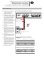
308 VCA Volume Control/
Loudness EQ
U
S
E
R
N
G
U
I
D
E
308 VCA Volume Control/Loudness
EQ User’s Guide
© July 2000 Symetrix, Inc.
All rights reserved.
Printed in the United States of America
Symetrix Part Number 53308-0A00
The information in this guide is subject to
change without notice. Symetrix, Inc. shall
not be liable for technical or editorial
errors or omissions contained herein; nor
is it liable for incidental or consequential
damages resulting from the furnishing,
performance, or use of this material.
Mention of third-party products is for informational purposes only and constitutes
neither an endorsement nor a recommendation. Symetrix assumes no responsibility with regard to the performance or use
of these products.
Under copyright laws, no part of this user
guide may be reproduced or transmitted
in any form or by any means, electronic or
mechanical, without permission in writing
from Symetrix, Inc. If, however, your only
means of access is electronic, permission
to print one copy is hereby granted.
Permission to copy the Architects and
Engineers Specificiations for written
proposals specifying equipment for sound
reinforcement systems is, also, granted.
Symetrix, Inc.
14926 35th Ave West
Lynnwood WA 98037-2303
USA
Tel:
425.787.3222
Fax:
425.787.3211
Web:
www.symetrixaudio.com
Email: [email protected]
Symetrix 308 VCA Volume Control/Loudness EQ User’s Guide
Contents
Before You Begin
2
Signal Flow Diagram
12
What Ships in the Box
2
Getting Help
2
Troubleshooting
13
Optional Rackmount Accessories
2
Notational Conventions in this User Guide
2
Hardware Specifications
14
Operational Safety Summary
3
Equipment Markings
3
Architects and Engineers Specifications
15
308 Product Information
4
Warranty
16
Product Summary
4
Features
4
Service
17
Making Hardware Connections
5
Declaration of Conformity
18
Overview of Rear Panel Connectors and Connections
5
Fast First-Time Setup
7
Controlling Channel Levels From a Potentiometer
or Voltage Ramp
8
Controlling Channel Levels by a Variable Resistor
9
Unbalanced Connections
10
Input and Output Connector Wiring
11
1
Symetrix 308 VCA Volume Control/Loudness EQ User’s Guide
Before You Begin
| What Ships in the Box | Getting Help | Optional Rackmount Accessories | Notational
Conventions in this User Guide | Operator Safety Summary | Equipment Markings
What Ships in the Box
Getting Help
The 308 unit
One PS-3 or PS-3E (export
version) power supply
If you have technical questions beyond the scope of this guide, please contact
our Technical Services Group in the following ways:
This user's guide
International customers (425) 787-3222
A warranty card
from 6:00 am to 4:30 pm Pacific Time Monday through Friday
You can register online at
www.symetrixaudio.com
T
F
US customers (888) 349-3222
(425) 787-3211
[email protected]
When you register the 308, you
get 4 extra years of warranty
coverage.
www.symetrixaudio.com
Optional Rackmount Accessories
MODEL
ITEM
DESCRIPTION
RM-3
19" Rackmount Tray
IU in height
FP-3
Filler Panel
Covers unused space when one 308
unit is mounted in the rack tray
PY-3
Y Power Cable
Connects a 308 with another 300 Series
product to the same power supply
RC-3
Remote Control
For use with the 308 unit
Contact your dealer or Symetrix for purchasing information.
Notational Conventions in this User Guide
Note
Identifies information that needs extra emphasis. Generally
supplies extra information to help you to better use the 308.
CAUTION
Identifies information that, if unheeded, may cause damage to
the 308 or other equipment in your system.
WARNING
Identifies information that, if ignored, may be hazardous to
your health or that of others.
CAPS
Controls, switches or other markings on the chassis of the 308.
2
Symetrix 308 VCA Volume Control/Loudness EQ User’s Guide
Before You Begin
| What Ships in the Box | Getting Help | Optional Rackmount Accessories
| Notational Conventions in this User Guide | Operator Safety Summary | Equipment Markings
Operator Safety Summary
Follow all warnings and instructions.
Install in accordance with the
manufacturer’s instructions.
Power Source This product is intended
to operate from a Symetrix PS-3 or PS-3E
power supply.
Grounding The chassis of this product is
grounded through the grounding conductor of the PS-3 or PS-3E power cord. To
avoid electric shock, plug the power cord
into a properly wired receptacle before
making any connections to the product. A
protective ground connection, by way of
the grounding conductor in the power
cord, is essential for safe operation. Do
not defeat the safety purpose of the
grounding plug. The grounding plug has
two blades and a third grounding prong.
The third prong is provided for your
safety. When the provided plug does not
fit your outlet, consult an electrician for
replacement of the obsolete outlet.
Danger from Loss of Ground If the
protective ground connection is lost, all
accessible conductive parts, including
knobs and controls that may appear to be
insulated, can render an electric shock.
Proper Power Cord Use only the power
cord and connector specified for the
product and your operating locale. Use
only a cord that is in good condition.
Protect the power cord from being walked
on or pinched, particularly at the plug,
convenience receptacle, and the point
where the cord exits from the apparatus.
Equipment Markings
Operating Location Do not operate this
equipment under any of the following
conditions: explosive atmospheres, in wet
locations, in inclement weather, improper
or unknown AC mains voltage, or if
improperly fused. Do not install near any
heat source such as radiators, heat
registers, stoves, or other apparatus
(including amplifiers) that produce heat.
Unplug this apparatus during lightning
storms or when unused for long periods of
time.
Stay Out of the Box To avoid personal
injury (or worse), do not remove the
product covers or panels. Do not operate
the product without the covers and panels
properly installed. Only use accessories
specified by the manufacturer. Clean only
with a damp cloth.
User-serviceable parts There are no
user serviceable parts inside the 308. In
case of failure, refer all servicing to the
factory. Servicing is required when the
308 has been damaged in any way, such
as when a power supply cord or plug is
damaged, liquid has been spilled or
objects have fallen into the apparatus, the
apparatus has been exposed to rain or
moisture, does not operate normally, or
has been dropped.
CAUTION
RISK OF ELECTRIC SHOCK
DO NOT OPEN
TO REDUCE THE RISK OF FIRE OR
SHOCK DO NOT EXPOSE
WARNING: ELECTRIC
THIS EQUIPMENT TO RAIN OR MOISTURE
DE CHOC ELECTRIQUE
AVIS: RISQUE
NE PAS OUVRIR
SEE OWNERS MANUAL. VOIR CAHIER D’INSTRUCTIONS.
No user serviceable parts inside. Refer servicing to qualified service personnel.
Il ne se trouve a l’interieur aucune piece pourvant entre reparée l’usager.
S’adresser a un reparateur compétent.
The lightning flash with arrowhead symbol
within an equilateral triangle is intended
to alert the user of the presence of
uninsulated “dangerous voltage” within
the product’s enclosure that may be of
sufficient magnitude to constitute a risk of
electric shock to persons. The exclamation
point within an equilateral triangle is
intended to alert the user of the presence
of important operating and maintenance
(servicing) instructions in the literature
accompanying the product (i.e., this user
guide).
CAUTION
To prevent electric shock, do not use the
polarized plug supplied with the unit
with any extension cord, receptacle, or
other outlet unless the blades can be
fully inserted.
3
Symetrix 308 VCA Volume Control/Loudness EQ User’s Guide
308 Product Information
| Product Summary | Features
Product Summary
The Symetrix 308 VCA Volume
Features
Zone Operation
Control the volume of a stereo signal
in a single zone or mono signals in
two zones.
Loudness EQ Circuit
Enhances program frequency response as volume is lowered.
Remote Level Control
Volume control by use of Symetrix
RC-3 Remote Control, linear potentiometers* located up to 500 ft. from
unit, or DC control voltages of 0 to 10
volts range*. Stereo signals may be
adjusted by one control.
Audio Inputs & Outputs
Rear-panel Euroblock connectors
accept balanced or unbalanced linelevel signals.
Control/Loudness EQ provides remote
level control and loudness EQ for
engineered sound systems. You set
the amount of loudness EQ compensation by adjusting rear panel EQ DEPTH
trimpots. These circuits may be
defeated entirely by turning the
trimpots fully counter-clockwise. The
308 is a half-rack unit that fits on a
shelf next to a mixer/amp or mounts
in a rack with optional Symetrix RM-3.
*user supplied
4
Symetrix 308 VCA Volume Control/Loudness EQ User’s Guide
Making Hardware Connections
| Overview of Rear Panel Connectors and Controls | Fast First-Time Setup
| Controlling Channel Levels From a Potentiometer or Voltage Ramp | Controlling Channel Levels
By a Variable Resistor | Unbalanced Connections | Input and Output Connector Wiring
Overview of Rear Panel Connectors and Controls
POWER
INPUT
EQ DEPTH
1
AUDIO OUT
1
2
AUDIO IN
1
2
2
SYMETRIX
PS-3 OR PS-3E
POWER
SUPPLY ONLY.
308
CONTROL
(VOLUME CONTROL POTS 10K OHMS LINEAR TAPER)
RAMP1 GND1 GND2 RAMP2 +24V
CTL1 +10V CTL2 GND
CONNECT TO
CONNECTION
CONNECTOR TYPE
WHAT IT DOES
POWER INPUT
7-pin DIN Connector
Accepts power only from Symetrix
PS-3, PS-3E, or PY-3 power supply.
CONTROL
Euroblock Connectors
Input connections for remote controls.
PIN
ASSIGNMENT
RAMP1
Ramp Output #1
Same control voltage applied to CTL1
appears here. Use it for controlling
channel 1 of multiple 308 units.
CTL1
Control Input #1
Connect a ramp voltage or the wiper
(W) of a 10k ohm linear taper potentiometer here for controlling channel
1 audio levels.
GND1
Control 1 Ground
Connect the ramp voltage ground or
the CCW (low) terminal of the pot
connected to CTL1 here.
+10V
+10 VDC Output
Provides the +10 VDC control voltage
for 10k ohm linear taper
potentiometer(s). Connect the pot
terminal CW (high) here. If using a
control pot for each channel, connect
the CW terminals from two pots here.
GND2
Control 2 Ground
Connect the ramp voltage ground or
the CCW (low) terminal of a 10k ohm
linear taper potentiometer here for
controlling channel 2 audio levels.
CTL2
Control Input #2
Connect a ramp voltage or the wiper
(W) of the pot connected to GND2
here.
RAMP2
Ramp Output #2
Same control voltage applied to CTL2
appears here. Use it for controlling
channel 2 of multiple 308 units.
GND
Ground
Provides ground connection for +24
VDC connections.
+24V
+24 VDC Output
Provides +24 VDC power for remote
controls requiring it.
5
Symetrix 308 VCA Volume Control/Loudness EQ User’s Guide
Making Hardware Connections
| Overview of Rear Panel Connectors and Controls | Fast First-Time Setup
| Controlling Channel Levels From a Potentiometer or Voltage Ramp | Controlling Channel Levels
By a Variable Resistor | Unbalanced Connections | Input and Output Connector Wiring
Overview of Rear Panel Connectors and Controls continues
CONNECTION
CONNECTOR TYPE
WHAT IT DOES
EQ DEPTH
Trimpots 1 and 2
Controls the amount of loudness EQ
compensation applied to their respective audio channels. They are set for
maximum loudness contour from the
factory (maximum mid-range attenuation). Can be independently adjusted. Once adjusted, the amount of
EQ compensation follows the volume
set by the remote controls.
At full volume (+10V control
voltage), the EQ response is flat and
the 308 gain is at unity (the 308 will
not add gain to your system).
At lowered volume, the midrange
response is reduced to a maximum of
–15 dB @ 1 kHz, effectively boosting
the bass and treble frequencies.
Turning these trimpots counterclockwise lessens the amount of loudness
EQ compensation.
Turning these trimpots fully counterclockwise turns off the EQ DEPTH
feature.
AUDIO OUT
Euroblock Connectors
Provides balanced line-level audio
output signals for their respective
channels. Use 2-conductor shielded
cable for all connections.*
AUDIO IN
Euroblock Connectors
Connect balanced line-level input
signals to these connectors for their
respective channels. Use 2-conductor
shielded cable for all connections.*
*For balanced use, the 308 follows
AES standards for balanced audio
circuits.
For unbalanced use, see in this
section:
Unbalanced Connections
Input and Output Connector Wiring
6
Symetrix 308 VCA Volume Control/Loudness EQ User’s Guide
Making Hardware Connections
| Overview of Rear Panel Connectors and Controls | Fast First-Time Setup
| Controlling Channel Levels From a Potentiometer or Voltage Ramp | Controlling Channel Levels
By a Variable Resistor | Unbalanced Connections | Input and Output Connector Wiring
Fast First-Time Setup
2
3
Connect your line-level audio
inputs and outputs to the
AUDIO IN and AUDIO OUT
Euroblock connectors.
Connect your remote controls to
the CONTROL Euroblock connectors. (If using a potentiometer,
see in this section, Controlling
Both Channels from a Single
Potentiometer. If using a
rheostat, see Controlling Channel
Levels By a Variable Resistor.)
Connect the external power
supply to the 308 unit, then
plug the power supply into an
AC outlet.
4
Apply line-level audio signal to
the inputs.
5
Adjust the remote controls to
maximum level. Then set your
system power amp levels to the
desired maximum level. As you
adjust the remote controls, the
308 passes audio signals. At full
volume setting, the 308 is at
unity gain.
6
Turn down the remote controls
to the lowest listening level you
expect the system to be operated at.
7
The EQ DEPTH trimpots are set
for maximum loudness contour
from the factory. At the lowest
VCA setting, the EQ DEPTH is
–15 dB @ 1k. Adjust the trimpots
counterclockwise if you want
less EQ response. To turn off
this feature, turn the trimpots
completely counterclockwise.
Basic Remote Setup Showing One Channel
CONTROL
EQ DEPTH
AUDIO OUT
1
2
(VOLUME CONTROL POTS 10K OHMS LINEAR TAPER)
CONNECT TO
SYMETRIX
PS-3 OR PS-3E
POWER
SUPPLY ONLY.
POWER
INPUT
RAMP1 GND1 GND2 RAMP2 +24V
CTL1 +10V CTL2 GND
1
2
CHANNEL 1
Control Voltage
0 to 10V
Ramp Generator GND
0 to 10V
GND
CTL
+10
Volume
Symetrix RC-3 Remote Control
SYMETRIX RC-3 REMOTE CONTROL PIN CONNECTION
TO THE 308 PINS
RC-3 Pins
308 Channel 1 Pins
308 Channel 2 Pins
+10V
+10V
+10V
CTL
CTL1
CTL2
GND
GND1
GND2
Fast Setup is complete.
RAMP/CONTROL VOLTAGE PIN CONNECTION TO THE 308 PINS
Device Pins
Ramp generator GND
Control voltage
308 Channel 1 Pins
308 Channel 2 Pins
GND1
GND2
CTL1
CTL2
7
AUDIO IN
1
2
308
1
Symetrix 308 VCA Volume Control/Loudness EQ User’s Guide
Making Hardware Connections
| Overview of Rear Panel Connectors and Controls | Fast First-Time Setup
| Controlling Channel Levels From a Potentiometer or Voltage Ramp | Controlling Channel
Levels By a Variable Resistor | Unbalanced Connections | Input and Output Connector Wiring
Controlling Channel Levels From a Potentiometer or Voltage Ramp
CONTROL
EQ DEPTH
AUDIO OUT
1
2
(VOLUME CONTROL POTS 10K OHMS LINEAR TAPER)
CONNECT TO
SYMETRIX
PS-3 OR PS-3E
POWER
SUPPLY ONLY.
POWER
INPUT
RAMP1 GND1 GND2 RAMP2 +24V
CTL1 +10V CTL2 GND
1
AUDIO IN
1
2
2
308
Connect the potentiometers to the
CONTROL Euroblock connectors. Its
pots must be 10k ohms linear taper,
and the cable should be 2-conductor
with shield. You can locate the
potentiometers up to 500 feet from
the 308 unit. Stereo signals can be
adjusted by using one potentiometer.
To use two potentiometers to control each channel
CHANNEL 1
CHANNEL 2
Control Voltage
Control Voltage
Ramp Generator GND
Ramp Generator GND
Potentiometer
CCW
W
CW
CW
W
CCW
To use one potentiometer to control both channels
CONTROL
EQ DEPTH
(VOLUME CONTROL POTS 10K OHMS LINEAR TAPER)
CONNECT TO
SYMETRIX
PS-3 OR PS-3E
POWER
SUPPLY ONLY.
POWER
INPUT
RAMP1 GND1 GND2 RAMP2 +24V
CTL1 +10V CTL2 GND
1
AUDIO OUT
1
2
AUDIO IN
1
2
2
308
Setup for Remote Control
CHANNELS 1 and 2
Control Voltage
Jumper connects RAMP1 and CTL2
Ramp Generator GND
Potentiometer
CW
W
CCW
POTENTIOMETER PIN CONNECTION TO THE 308 PINS
Potentiometer Pins
308 Channel 1 Pins
308 Channel 2 Pins
CW (high)
+10V
+10V
W (Wiper)
CTL1
CTL2
CCW (low)
GND1
GND2
8
Symetrix 308 VCA Volume Control/Loudness EQ User’s Guide
Making Hardware Connections
| Overview of Rear Panel Connectors and Controls | Fast First-Time Setup
| Controlling Channel Levels From a Potentiometer or Voltage Ramp | Controlling Channel
Levels By a Variable Resistor | Unbalanced Connections | Input and Output Connector Wiring
Controlling Channel Levels By a Variable Resistor (ie., a rheostat)
Use this setup when you need a
remote output mute. Connecting a
normally-open mute push button or
relay contact in parallel with the
control resistance results in maximum
attenuation when the switch contacts
are closed. The 308 is not damaged
by such a connection.
CONTROL
EQ DEPTH
(VOLUME CONTROL POTS 10K OHMS LINEAR TAPER)
CONNECT TO
SYMETRIX
PS-3 OR PS-3E
POWER
SUPPLY ONLY.
POWER
INPUT
RAMP1 GND1 GND2 RAMP2 +24V
CTL1 +10V CTL2 GND
1
AUDIO OUT
1
2
AUDIO IN
1
2
2
308
This setup provides compatibility with
certain remote volume control panels.
A resistance of 10K ohms results in
unity gain. A resistance of 0 ohms
(short circuit) results in maximum
attenuation. You do not need a
connection to the +10V terminal.
To use two rheostats to control each channel
CHANNEL 2
CHANNEL 1
Mute
Mute
Rheostat
CCW
W
W
CCW
To use one rheostat to control both channels
CONTROL
EQ DEPTH
(VOLUME CONTROL POTS 10K OHMS LINEAR TAPER)
CONNECT TO
SYMETRIX
PS-3 OR PS-3E
POWER
SUPPLY ONLY.
POWER
INPUT
RAMP1 GND1 GND2 RAMP2 +24V
CTL1 +10V CTL2 GND
1
AUDIO OUT
1
2
AUDIO IN
1
2
2
308
Setup for Remote Output Mute
CHANNELS 1 and 2
Jumper connects RAMP1 and CTL2
Mute
Rheostat
W
CCW
RHEOSTAT PIN CONNECTION TO THE 308 PINS
Rheostat Pins
308 Channel 1 Pins
308 Channel 2 Pins
W (Wiper)
CTL1
CTL2
CCW (low)
GND1
GND2
9
Symetrix 308 VCA Volume Control/Loudness EQ User’s Guide
Making Hardware Connections
| Overview of Rear Panel Connectors and Controls | Fast First-Time Setup
| Controlling Channel Levels From a Potentiometer or Voltage Ramp | Controlling Channel Levels
By a Variable Resistor | Unbalanced Connections | Input and Output Connector Wiring
Unbalanced Connections
We do not recommend unbalanced
input and output connections, but
follow these instructions if you must
do so.
Unbalanced Audio Output Connections
1
Connect the (+) terminal of the 308 to the (+ or high) of the unbalanced
input connector.
2
Make no connection to the (–) terminal of the 308.
3
Connect the cable shield to the ground of the 308 and at the unbalanced
input connector.
Notes
The output signal level of the 308 will be 6 dB lower when driving an unbalanced
input without a transformer or matching interface device. To avoid this, use the
Symetrix 303 Interface Amplifier or 307 Dual Isolation Transformer.
If you experience hum or noise, make sure that both the 308 and the device with
the unbalanced input are grounded on the same AC mains circuit. If this is not the
source of the noise problem, isolate the balanced output from the unbalanced
input using the Symetrix 303 or 307.
Unbalanced Audio Input Connections
1
Connect the incoming signal (+ or high) to the (+) terminal of the 308.
2
Connect the incoming signal ground to the (–) terminal of the 308.
3
Connect the cable shield to the ground connection of the 308 only
(leave the other end unconnected).
Notes
The 308 is designed to operate at the +4 dBu level. If the unbalanced output(s) of
the device feeding the 308 is –10 dBV (semi-pro or consumer level), use the
Symetrix 303 Interface Amplifier to convert the unbalanced source to a balanced
signal, and boost the –10 dBV signal to the +4 dBu level.
If you experience hum or noise, make sure that both the 308 and the device with
the unbalanced output are grounded on the same AC mains circuit. If this is not
the source of the noise problem, isolate the balanced input from the unbalanced
output using a Symetrix 303 or 307.
10
Symetrix 308 VCA Volume Control/Loudness EQ User’s Guide
Making Hardware Connections
| Overview of Rear Panel Connectors and Controls | Fast First-Time Setup
| Controlling Channel Levels From a Potentiometer or Voltage Ramp | Controlling Channel Levels
By a Variable Resistor | Unbalanced Connections | Input and Output Connector Wiring
Input and Output Connector Wiring
METHOD
CONNECTOR
CHANNEL
Input
Balanced Terminal Strip
Input
= Circuit Ground
= High
= Low
132
Balanced Female XLR
Pin 1
Pin 2
Pin 3
Input
Balanced TRS Plug
Tip
Ring
Sleeve
= High
= Low
= Shield
TIP
RING
SLEEVE
Input
Unbalanced TS Plug
Tip
Sleeve
TIP
= High
= Low + Shield
SLEEVE
Input
Unbalanced RCA Plug
Tip
Sleeve
Cable Shield
= High
= Low
= Not Connected
Output
= Circuit Ground
= High
= Low
231
Balanced Male XLR
Pin 1
Pin 2
Pin 3
Output
Unbalanced TS Plug
Tip
Sleeve
Wire Low
= High
= Shield
= Not Connected
TIP
SLEEVE
11
Symetrix 308 VCA Volume Control/Loudness EQ User’s Guide
Signal Flow Diagram
LEVEL
VCA
BALANCED
INPUT
SUBTRACT
EQ
VCA
BANDPASS
FILTER
DEPTH
EQ VCA
DC CONTROL
10V REF
REMOTE
CONTROL
LEVEL VCA
DC CONTROL
RAMP
OUT
12
BALANCED
OUTPUT
Symetrix 308 VCA Volume Control/Loudness EQ User’s Guide
Troubleshooting
SYMPTOM
PROBABLE CAUSE/WHAT TO DO
No output
Check cables and connections to see if:
• Inputs are driving outputs, and outputs are driving inputs.
• That there is a signal from the source and that it is getting to the 308.
Check if unit is plugged in.
Hum or buzz in output
Check input and output connector wiring.
Check for ground loop problem. Inspect related system equipment grounding to see that all system components are on the same AC ground.
Distortion
Check input signal.
Check if line input signal may be too hot.
If using a high setting for your maximum audio level, you may be overloading the input to your amplifier; lower the audio level.
Check if something else is clipping in the signal chain.
Noise (hiss)
Check input signal levels. The 308 is intended to operate at or near “line”
level (+4dBu is nominal). Make sure that the signal you are feeding to the
308 is a line level signal, not mic level.
Check that all systems components are on the same AC ground.
Check gain settings on upstream equipment. The system gain structure
should be such that the 308 receives +4dBu nominal signal.
No LED display
Check if unit is plugged in.
Verify that AC outlet works.
13
Symetrix 308 VCA Volume Control/Loudness EQ User’s Guide
Hardware Specifications
Input/Output
Maximum Input Level
Maximum Output Level
Input Impedance
Output Impedance
Input Common Mode Rejection
Performance Data
Frequency Response
THD+N
Residual Output Noise
Gain Control
Equalization
Analog Control
Control inputs accept any of
Gain
Ramp Out
Auxiliary Power Out
+20 dBu balanced, +20 dBu
+22 dBu balanced, +18 dBu
>20k ohms balanced, >10k ohms
200 ohms balanced, 100 ohms
20 Hz to 20 kHz +0, – 0.5 dB
(with no equalization applied)
20 Hz to 20 kHz +0, –1.5 dB (at unity gain with max EQ depth)
<0.025% at unity gain, 0 dBu in/out
– 95 dBu typical at unity gain
0 dB (unity) to – 65 dB
–15 dB max @ 1 kHz
(a) 10k linear rheostat to ground
(b) 10k linear potentiometer from +10 reference output to ground
(c) 0 to 10 VDC control voltage
(d) Symetrix RC-3 Remote Control
Unity at +10 VDC and max attenuation at 0 VDC
Buffered duplicate of the Control In voltage
+24 VDC ± 10%, 100 milliamps max continuous load
Connections
Inputs, Outputs, Control Ports
AC Power In
Physical
Size (H x W x D)
Shipping Weight
Electrical
Power Requirements
PS-3
PS-3E
unbalanced
unbalanced
unbalanced
unbalanced
>40 dB
Euroblock
7-pin DIN
1/2 rack unit
1.75 in. x 8.5 in. x 6.5 in. / 4.445 cm x 21.59 cm x 15.875 cm
4.5 lbs.
12W maximum, Symetrix PS-3 or PS-3E only
115V, 60 Hz AC nominal
230V, 50 to 60 Hz AC nominal
In the interest of continuous product
improvement, Symetrix, Inc. reserves
the right to alter, change, or modify
these specifications without prior
notice.
14
Symetrix 308 VCA Volume Control/Loudness EQ User’s Guide
Architects and Engineers Specifications
The VCA volume control / loudness EQ
shall provide two channels of remote
level adjustment and automatic
loudness EQ compensation for
controlling a stereo signal in one zone
or mono signals in two zones. There
shall be a voltage controlled amplifier
(VCA) in each channel controlled by
either a 0 to 10 VDC ramp signal or
by a 10k ohms linear taper potentiometer or other compatible remote
control, such as the Symetrix RC-3.
Potentiometers may be located up to
500 feet from the VCA volume
controller. The loudness EQ will be
flat at full volume and the output gain
will be at unity. At lower volumes, the
loudness EQ shall automatically
effectively boost the bass and treble
frequencies by lowering the midrange
response. The maximum midrange
attenuation will be –15 dB @ 1 kHz.
The VCA volume control / loudness EQ
shall provide two balanced line-level
audio inputs on Euroblock connectors.
The input impedance shall be at least
20k ohms balanced, 10k ohms
unbalanced. The maximum input level
shall be +20 dBu balanced, +20 dBu
unbalanced. There shall be two
balanced line-level audio outputs on
Euroblock connectors. The output
impedance shall be 400 ohms balanced, 200 ohms unbalanced. The
maximum output level shall be +22
dBu balanced, +18 dBu unbalanced.
Screwdriver adjustable trimpots shall
be provided for selecting the amount
of loudness EQ compensation for each
channel. Nine inputs for remote
control connections shall also be
provided on Euroblock connectors.
These inputs shall consist of: Ramp
Out, Control In, Ground for each
channel; +10 VDC Out; Ground; +24
VDC Out.
The VCA volume control / loudness EQ
shall operate by means of a Symetrix
PS-3 connected to 115 VAC nominal,
(95–130 VAC), 60 Hz or a Symetrix
PS-3E connected to 230 VAC nominal,
(165–255 VAC), 50 to 60 Hz.
The VCA volume control / loudness EQ
shall be a Symetrix model 308 VCA
Volume Control / Loudness EQ.
A front panel power indicator shall be
provided.
The frequency response shall be +0,
–0.5 dB, measured between 20 Hz
and 20 kHz. THD+N shall be less than
0.025% measured at unity gain.
Power consumption shall be 12W
maximum.
The unit shall occupy half of the width
of one rack space. The physical
dimensions shall be 1.75 in. (H) x 8.5
in. (W) x 6.5 in. (D) / 4.445 cm (H) x
21.59 cm (W) x 15.875 cm (D).
15
Symetrix 308 VCA Volume Control/Loudness EQ User’s Guide
Warranty
Important Information
Regarding Your Warranty
We would like to offer you an incentive to
complete our product registration form.
Either fully complete and mail your product
registration card or register online at
www.symetrixaudio.com. You will then
have a total of 5 years of warranty
coverage, under the terms and limitations
as set forth below, without additional cost.
If you don’t register your product, you will
still receive one year of warranty coverage,
but it only takes a minute to fill out the
card or register online and we won’t share
your personal information with others.
Following are the terms and limitations of
the Symetrix warranty.
Warranty
reserves the right to refund a prorated
portion of the purchase price in full
satisfaction of all warranty claims. A refund
of the purchase price is prorated as
follows: 100% through year one, 80%
through year two, 60% through year three,
40% through year four and 20% through
year five.
In order to serve you better we request
that the Buyer shall, prior to shipping
Product to Symetrix for warranty service,
contact Symetrix and secure a Return
Authorization Number that shall be
included with the returned Product. This
will facilitate our efforts to keep track of
your Product and process your warranty
repair as quickly as possible. Buyer will
prepay all freight charges to ship the
Product to Symetrix for warranty inspection
and service. This warranty is subject to
Symetrix’s inspection of the Product at its
facilities and, upon Symetrix’s request,
satisfactory proof of purchase (dated copy
of original retail dealer’s invoice.)
Symetrix, Inc. expressly warrants to the
original purchaser (“Buyer”), subject to the
terms and conditions set forth below, that
the Product will be free from defects in
material and workmanship as a result of
normal commercial use for one (1) year
from the date of purchase. This warranty
will be automatically extended (subject to
the additional limitations set forth below)
for an additional four years if the Warranty
Registration is completed and returned to
Symetrix (or completed online) within
thirty (30) days of the date of delivery.
Symetrix reserves the right to effect
repairs to the product with reconditioned
components/parts. Products once repaired
under warranty will be shipped to Buyer
freight prepaid by Symetrix via United
Parcel Service (surface) or any similar
shipper, to any location designated by
buyer within the Continental United States.
At Buyer’s request and expense Product
will be returned via airfreight. Outside the
continental United States, repaired or
replaced products will be returned freight
collect.
Symetrix’s warranty obligation is limited to
the repair, replacement, or refund at
Symetrix’s sole discretion, of the part or
parts of the Product which may thus prove
defective in materials or workmanship
within one year from date of purchase (or
five years from the date of purchase if
Buyer has registered its purchase as
provided above) under normal use and
which our examination discloses to our
satisfaction to be thus defective, provided
that Buyer gives Symetrix prompt notice of
its warranty claim and satisfactory proof
thereof.
THIS WARRANTY IS EXPRESSLY IN LIEU OF
ALL OTHER WARRANTIES EXPRESS OR
IMPLIED, ARISING BY LAW OR OTHERWISE
(INCLUDING, WITHOUT LIMITATION ANY
OBLIGATIONS OF THE SELLER WITH
RESPECT TO CONSEQUENTIAL DAMAGES)
INCLUDING THE WARRANTIES OF MERCHANTABILITY AND FITNESS FOR USE
AND OF ALL OTHER OBLIGATIONS OR
LIABILITIES ON OUR PART, AND WE
NEITHER ASSUME, NOR AUTHORIZE ANY
OTHER PERSON TO ASSUME FOR US, ANY
OTHER LIABILITY IN CONNECTION WITH
THE SALE OF THE PRODUCT. THIS
WARRANTY SHALL NOT APPLY TO THIS
PRODUCT OR ANY PART THERE OF WHICH
HAS BEEN SUBJECT TO ACCIDENT,
NEGLIGENCE, ALTERATION, ABUSE, OR
MISUSE. WE MAKE NO WARRANTY
Symetrix will make every reasonable effort
to ensure that parts are available to
support the repair of our products under
warranty. In the event that a product or
component part thereof becomes obsolete,
unavailable or irreparable, Symetrix
WHATSOEVER IN RESPECT TO ACCESSORIES OR PARTS NOT SUPPLIED BY US. THE
TERM “ORIGINAL PURCHASER,” AS USED
IN THIS WARRANTY SHALL BE DEEMED TO
MEAN THAT PERSON OR COMPANY THAT
ORIGINALLY PURCHASED THE PRODUCT.
This Symetrix product has been designed
and manufactured for use in professional
and studio audio systems and is not
intended for other usage. This warranty
only applies to Buyers using the Product in
professional and studio audio systems.
With respect to others, including but not
limited to consumers for personal, family,
or household use, Symetrix expressly
disclaims all warranties, including but
not limited to warranties of merchantability and fitness for a particular
purpose and the express warranties as
otherwise provided herein.
Symetrix reserves the right to modify the
design or make additions to, or improvements to, its product lines without making
similar upgrades to Product purchased by
Buyer. Symetrix does not authorize any
third party, including any dealer or sales
representative, to assume any liability,
effect any repairs or modifications to the
Product, or make any additional warranties
or representation regarding the Product or
Product information on behalf of Symetrix.
Symetrix’s total liability on any claim,
whether in contract, tort (including
negligence) or otherwise arising out of,
connected with, or resulting from the
manufacture, sale, delivery, resale, repair,
replacement or use of Product will not
exceed the purchase price of the Product or
any part thereof which gives rise to the
claim. In no event will Symetrix be liable
for any incidental or consequential
damages including but not limited to
damage for lost revenue, cost of capital,
claims of customers for service interruptions or failure to supply, and costs and
expenses incurred in connection with labor,
overhead, transportation, installation or
removal of products or substitute facilities
or supply houses as a result of Product
failure.
This limited warranty gives Buyer certain
rights. Buyer may have additional rights
under applicable law.
16
Symetrix 308 VCA Volume Control/Loudness EQ User’s Guide
Service
Where to Get Service
To Get Your 308 Unit Repaired (US Customers Only)
If ouside of the USA
1
If you have determined that your 308
requires repair services and you live
outside of the United States, please
contact your local Symetrix dealer or
distributor for instructions on how to
obtain service.
If inside the USA
Symetrix will perform in-warranty or
out-of-warranty service on any
product it has manufactured for a
period of five years from date of
manufacture. If you reside in the
USA, then proceed as follows:
(888) 349-3222, Monday through Friday, 6:00 am to 4:30 pm Pacific
Time.
Have your serial number ready to give to the customer service representative.
2
Pack the unit in its original packaging materials.
3
Include your name, address, daytime telephone number, and a brief
statement of the problem.
4
Write the RA number on the outside of the box.
5
Ship the unit to Symetrix, freight prepaid. We do not accept freight
collect shipments.
Symetrix, Inc.
14926 35th Ave West
Lynnwood WA 98037
In-Warranty Repairs
Repairs made in-warranty will cost
you only one-way freight charges.
We’ll prepay the return (surface)
freight. Of course, if the repair is due
to operator error, parts and labor will
be charged. If there are charges for
the repair costs, you will pay for the
return freight. All charges will be COD
unless you have made other arrangements (prepaid, Visa, or Mastercard).
Out-of-Warranty Repairs
Call our Customer Service Department for a return authorization (RA)
number.
If You Don't Have Factory Packaging Materials
If you send us your product in substandard packaging, we will charge you for
factory shipping materials. If you don’t have the factory packaging materials, do
the following:
1
Select an oversized carton.
2
Wrap the unit in a plastic bag, and surround it with bubble-wrap.
3
Pack the box full of Styrofoam peanuts. Be sure there is enough clearance in the carton to protect the rack ears.
We will return the unit in Symetrix packaging.
If the warranty period has passed,
you’ll be billed for all necessary parts,
labor, packaging materials, and
freight charges.
17
Symetrix 308 VCA Volume Control/Loudness EQ User’s Guide
Declaration of Conformity
We, Symetrix, Inc.
14926 35th Avenue West, Lynnwood, Washington USA
declare under our sole responsibility that the product:
308 VCA Volume Control/Loudness EQ
to which this declaration relates, is in conformity with the following standard:
EN 55103-2
Electromagnetic Compatibility—Product Family Standard for Audio, Video, and
Entertainment Lighting Control Apparatus for Professional Use
Part 2: Immunity
PS-3E power supply complies with this code:
EN 60065
Safety Requirements for Mains Operated Electronic and Related Apparatus for
Household and Similar General Use
The technical construction file is maintained at:
Symetrix, Inc.
14926 35th Avenue West
Lynnwood, WA 98037-2303
USA
The authorized representative located within the European Community is:
World Marketing Associates
P.O. Box 100
St. Austell, Cornwall, PL26 6YU, UK
Date of issue: May 30, 2000
Place of issue: Lynnwood, Washington USA
Authorized signature:
Dane Butcher, President
18
301
Low Distortion Compressor/Limiter
302
Dual Microphone Preamplifier
303
Interface Amplifier
304
Headphone Amplifier
305
Distribution Amplifier (1x4)
306
Preamp/Ducker
307
Dual Isolation Transformer
308
VCA Volume Control/Loudness EQ
372
SPL Computer
402
Dual Output Delay
420
Stereo Power Amplifier
421M
AGC-Leveler
422
Stereo AGC-Leveler
440
Foreground Audio Controller
450
Dual Zone Priority Mixer
501
Peak-RMS Compressor/Limiter
501-01
Peak-RMS Compressor/Limiter
506E
Headphone Amplifier
527E
Voice Processor
528E
Voice Processor
531E
Graphic Equalizer
532E
Graphic Equalizer
533E
Graphic Equalizer
551E
5-Band Parametric EQ
552E
Dual 5-Band Parametric EQ
562E
Windowing Expander/Gate
565E
Dual Compressor/Limiter/Expander
571
SPL Computer
571S
SPL Computer Slave
572
SPL Computer
581E
Distribution Amplifier (4x4)
606
Delay F/x Machine
610
Broadcast Audio Delay
628
Digital Voice Processor
9022
2x2 DSP Engine
RC-1
628 Remote Control
RC-2
440 Remote Control
RC-610
Remote Control
www.symetrixaudio.com